Twice before, I’ve run into problems with the lines on the LogoChip’s port A not working the way I expected–while programming an interface to the A6276 LED driver, and again when trying to interface to the DS1302 real-time clock. The second time I ran into it, I fixed the problem by changing port A out of analog input mode–but didn’t know why that made a difference. Last week, poring over the PIC18F2320 datasheet, I finally figured out what’s going on and why the analog input mode matters.
I was working on output routines for TASD’s Thing 3: Simple Outputs, and we’re using port A because it’s the most conveniently placed on the LogoBoard. Every time I’d do a setbit or clearbit command against a line on port A, all the other outputs would change to 0.
Tom McGuire had run into this problem recently, and worked around it by reading and writing the port A latch, LATA, instead of the port register itself. But that still didn’t explain why it was happening in the first place. So I sat down with the datasheet and looked at the port operation diagrams.
Generic I/O Port
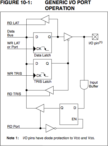
Here’s the diagram for a generic I/O port, from page 103 of the datasheet. Writing to the port or latch register (WR LAT or Port) puts data into the data latch, which is accessible by reading the latch (RD LAT) register. Additionally, when the data direction latch (TRIS latch) is in output mode, the data latch drives the I/O pin for output. Finally, the input buffer continually reads the I/O pin (even when outputting) and makes its current state accessible by reading the port register (RD Port).
So you can always write output data to the port or latch register; and when the port is in output mode, the last data written will be output to the pin. The last data written is always readable from the latch register; and when in output mode, the data is also readable from the port register.
Port A
Now look at port A, from page 103:
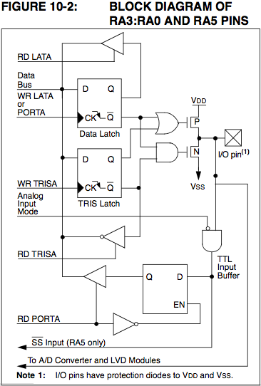
The most visible difference is that the simple output buffer from the data latch to the I/O pin has been replaced by an arrangment of an OR gate, an AND gate, and N- and P-channel FETs. As far as I can tell, there’s no operational difference between the two–Figure 10-2 simply shows what’s happening in more detail.
More significant is the addition of the Analog Input Mode line controlling the input buffer–this is the crux of my problem. When port A pins are receiving analog input, it doesn’t make sense to feed that input into a TTL register–in fact, it could cause excessive power draw and overheating. So the input signal is gated by the analog input mode before feeding to the port A read line (RD PORTA).
setbit and clearbit
The reason this matters is that the LogoChip’s setbit and clearbit commands are read-modify-write operators–they read the value of their target, OR or AND that value with a constant, and write it back to the target. When that target is the port A latch register, all works as it should–the latch is read directly back out the RD LATA line.
When the target is the port A data register, however, the current value is read through the input buffer, which is gated by the analog input mode line. When the pin is set in analog input mode, even though the data direction is set to output, the port data cannot be read because the gate is off, and always returns a 0.
So when setbit <bit> porta attempts to change one bit, it tries to read PORTA and returns %00000000 rather than the value of the data latch. It then sets one bit and writes the new (mostly-cleared) byte back out to the port A data latch–clearing every other bit of port A in the process.
Workarounds and Solution
Two workarounds are obvious. Tom’s method was to manipulate the port A latch (LATA) instead of the port A data register (PORTA). The latch can always be read and written directly, so this works flawlessly. My only objection is that porta is already defined as a constant in LogoChip Logo. I’m not wild about having to teach students to define a new constant for lata and then use lata, portb, and portc.
The second workaround is also simple. When using the LogoChip setbit and clearbit commands, clear the analog input mode on any pin you want to use as an output. Because the order of analog input pins is predetermined (A0, A1, A2, A3, A5, . . .), this might mean rearranging the pinouts–you can no longer have A0 and A2 as analog inputs and A1 as an output, for example. But it’s a pretty easy method.
The true fix is equally simple. Where port A’s TTL input buffer is gated by (active-low) analog input mode, it should in fact by gated by (active-low) analog input mode OR (TRIS Latch is set for output). That is, any time the pin is NOT in analog input mode, OR the pin is set for output, pass the pin’s value to the port data read buffer. I don’t see any drawbacks to this solution, other than the cost of one additional OR gate.
Having taken the time to figure that out, I’m rather surprised that Microchip didn’t build the PIC that way.
Hi Keith,
Thanks for publishing this information. I have a simple question – a PIC datasheet from MicroChip mentions that “All write operations are read-modify-write” which is also what you point out on this page. Why is this? If I am outputting a “1″ through a pin, why do I need to know what is currently on that pin?
Many thanks -
Todd S.
Sr Sw Eng (but a noob in Electronics)
Hi, Todd!
If you’re intending to write the whole (byte-wide) port register, I can’t think of any reason it should read first.
If you’re modifying a single bit, rather than creating a new opcode (or microcode) to twiddle one bit of a port register, it makes more sense to read in the register contents, manipulate them with traditional bitwise logic to set/clear the bit you want to change, and write them back out (all using common, existing opcodes). I think that’s what they mean when they say read-modify-write.
Does that help any?
Keith, thanks for the response.
As I understand it, “read-modify-write” is an atomic operation performed by the chip itself. During this operation, the user code does not have an opportunity to intervene. Am I correct?
As for the opcodes you mention, I am not clear what you are referring to. (Are opcodes related to the LogoBoard?)
Todd S.
I feel so old-fashioned . . . I guess the term opcodes has gone out of vogue in favor of instruction set, or some such?
So now I’m looking at the PIC18F2320 instruction set, and there are instructions to manipulate single bits in registers. But at a microcode level — how that instruction is implemented in the chip’s hardware — I’m quite certain it doesn’t have access to address a single bit within a register. Rather, it reads the whole register, ORs it with the bit to set or ANDs it with the inverse of the bit to clear, and writes it back.
Even though it may be atomic and happen in a single clock cycle, it’s still easier to build the chip to manipulate bits via read-modify-write (which shares microcode circuitry with other operations) than to make microcode that can directly access a single bit without touching the rest of the byte.
Internally, the data bus is eight bits wide. (Maybe it’s sixteen, but whatever.) Think about what it would mean for bus design if you could specify not only an address to access, but also a single bit for the bus to access, and the bus would only enable reads/writes to that individual line on the bus. Much more complex than read-modify-write.
I see. I guess what confused me about Microchip stating this fact (i.e. that internally the write’s are read-modify-write) is why it would be of use to the end-user — did they feel they had to mention it because of side-effects that this operation could have? Other than saying “that’s interesting” when reading the datasheet, what am I supposed to do w/ this fact when I’m programming the chip?
Thanks -
Todd S.
Yup, I assume they mention it because of the side effects.
I’d have to think carefully to make sure this is right, but here’s another possible side effect:
Set a port as all outputs and write values to the lines. Now set bits 4-7 as inputs, clear bit 0, then set 4-7 as outputs again.
You’d expect bits 4-7 to still have the same values they did the last time you set them as outputs. In fact, they’re going to have the values of their inputs at the time you cleared bit 0, thanks to read-modify-write.
Hardware side effects can be tricky.
Many THANKS for this exchange. (PS: Will test your example, as actually seeing something really drives in the point.)
I also look forward to more articles on your site. They are much appreciated.
Todd S.