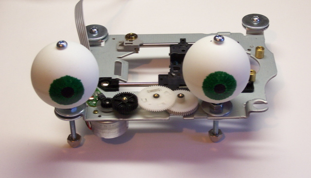
Back in mid-February, I wanted to demonstrate motor control with the LogoChip to class, but it’s hard to see what a motor is doing unless it’s geared down and attached to something. I decided to make googly eyes that could look around, and here’s how I went about it.
CD Read Sled
Although the motion of each individual eye is rotary (right to left; these can’t look up and down), to synchronize their actions, I needed linear motion.
Digression: Predator species have eyes on the front of their face, to triangulate the distance to their target. Prey have eyes on the sides of their heads, to keep the widest possible view of their surroundings and watch out for predators. Predators’ eyes generally move in synchronization. Of course, they may look slightly inward when watching a nearby object (binocular convergence; think of looking cross-eyed at your nose); but for a simple model like this, two eyes always looking in exactly the same direction is adequate.
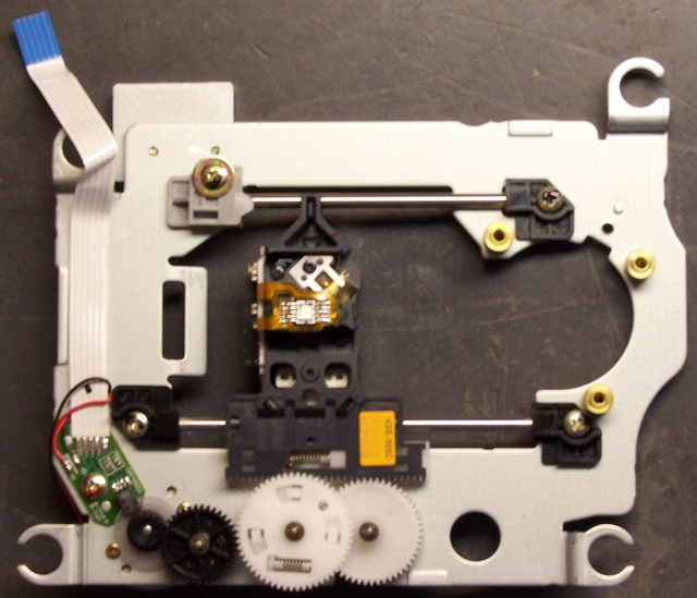
I figured my best shot was something from a dead CD-ROM drive, so I went down to examine my stash. What I call the read sled assemblies looked the most promising–they’re the ones that move the read head in and out along the radius of the disc to find the right position to play. The tray motors might also work, but the trays have a good 5″ range of motion. The ∼2″ range of the read sled seemed much more useful.
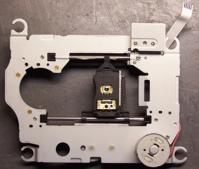
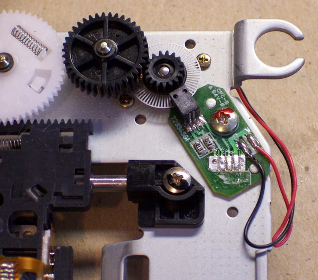
Several of the assemblies I examined used a stepper motor, but I wanted to demonstrate a simple DC motor, so I kept looking. Finally I came across this one, which had a DC motor (on the underside), a nice geartrain, and an optical encoder (the faint grey circle between the green PCB and the medium black gear) to determine the position of the sled.
The motor was mounted from the back side, and the optical disk was press-fitted to its shaft.
Reverse-Engineering the Optical Assembly
I was interested in trying to reuse the optical assembly so that I too (well, my program) would know where the sled was, so I desoldered the flex pcb ribbon cable and set about figuring out the connections on the PC board.
The larger black rectangle that overlaps the optical disk was obviously an optointerruptor–one side has an LED and the other side some kind of optical sensor. When a hole in the disk passes between them, light is transmitted; when a bar passes between, the light is interrupted, and the receiver can tell the difference.
The two smaller black rectangles (southwest of the screw head) are surface-mount resistors, reading “181″ (180Ω) and “752″ (7.5KΩ). I could visually follow some of the traces (the light green lines) on the board, but I got lost with exactly what happens underneath the resistors.
I assigned numbers to the five solder pads from the cable, arbitrarily numbering from the outer edge of the board. (In retrospect, that was incorrect–the pad to the left in this photo is shaped differently than the others; that makes it pin number 1. Ah well.) Then I made this table (actually edited here on my blog–all the notes have been sitting around for six weeks, and it’s only the narrative that I’m adding later) describing where each pin went, to the best of my visual acuity.
| Pin | Connection |
|---|---|
| 1 | motor black wire |
| 2 | motor red wire |
| 3 | interruptor |
| 4 | interruptor end of 7.5KΩ resistor |
| 5 | both resistors |
Pins 1 and 2 obviously run to the motor, and it was pretty clear that they didn’t have any connections to pins 3-5. So I used my ohmmeter to measure the resistance in each direction between each pair of pins out of 3-5. I got this:
| 4 → 3: 50KΩ 3 → 4: ∞ |
5 → 3: 40KΩ 3 → 5: ∞ |
5 → 4: 7.5KΩ 4 → 5: 7.5KΩ |
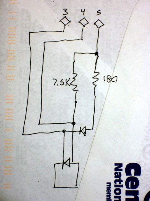
It was obvious that pins 4 and 5 were connected directly via the 7.5KΩ resistor. It was also apparent that there were diodes from pin 4 to 3 and from pin 5 to 3. That gave rise to this diagram:
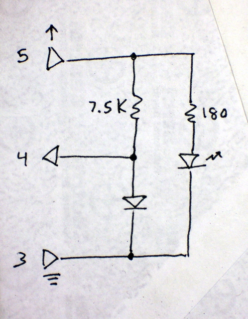
Which made a lot more sense once I redrew it like this:
Pin 5 is the supply voltage, pin 3 the ground, and pin 4 the readout of the voltage divider between the 7.5KΩ resistor and the photosensitive diode. Voila!
Using the Optical Encoder
A 180Ω current-limiting resistor with a 5V supply would give ∼24mA of current through the LED, and that seemed a little high. I’m guessing that part of the circuit ran on 3.3V, making the LED current ∼14mA–a more reasonable value.
I wanted to shoot for 15mA, so 4.3V / 15mA ≅ 290Ω, of which 180Ω was already in the circuit, leaving 110Ω to add. I had a 120Ω resistor in my bin, so 4.3V / (180Ω + 120Ω) ≅ 14mA, which was close enough. I used the 120Ω resistor to wire pin 5 to the 5V supply, placing it in series with both diodes. (I figured its impact on the 7.5KΩ resistor and photodiode whould be negligible.)
Turning the encoder wheel very slowly and carefully and reading the voltage at pin 4 yielded a minimum voltage of .77V and a peak of 3.4V. (Alas, I don’t remember which was when the light was blocked and which when it was passed . . . probably the photodiode conducted and pulled it down to .77V when light was passing . . . but I don’t know that I really care.)
I didn’t really want to have to use an A/D converter input and deal with a 10-bit numeric value when all I needed to know was whether the light was blocked or passing. But I wasn’t wild about feeding a continuously varying analog voltage into a TTL input–it tends to make them overheat. Happily, the PIC datasheet (p. 102) revealed that pin A4 has a Schmitt trigger input, and my problem was solved.
A Schmitt trigger has hysteresis–the input signal has to rise above a certain point (the “high-water mark”) before it reads high, then fall below a lower point (the “low-water mark”) before it reads low. It’s intended for reading digital values from analog signals, it was exactly what I needed, and it worked exactly as desired. I fed the optointerruptor signal into A4 and got clean, predictable digital results.
Next Steps
That’s probably long enough for one post. Next: Building the eyeball assembly and programming the motor.
Keith,
I assume that you are from Newton, KS. I saw you blog listed on the EDA Forum and I thought I would stop by and say hi. I am a PCB Engineer in Wichita and living in Newton. What tools are you using for your PCB work?