or
A Well-Stocked Junk Bin is the Mother of Having Everything You Need
July 7, 2008
Welcome, MAKE: Blog readers!
Whoever posted this to the MAKE: Blog missed what I think is the more interesting accomplishment — over the weekend, I put (most of) the polishing touches on an Arduino library to read multiple quadrature encoders reliably in an interrupt service routine, instantiating them as objects so they’re extremely easy to use with essentially no code.
You are of course welcome to read here about the rotary quadrature encoder itself; then if you’re interested, head to LED Calculator with Rotary Quadrature Encoder for Target System Voltage Selection for the Arduino library.
After the tragic disappointment of finding that my salvaged printer rotary encoder was optical (and I didn’t feel like dealing with the optoreflector circuitry), I mourned for a day, then got over my bad self and thought about what else uses rotary encoders.
Some recent stereos do, especially ugly boom boxes and (non-ugly) car stereos, typically for the digital tuner knob that can rotate forever and ever. And fortunately, I have some of each in the junk bin.
VW Car Stereo
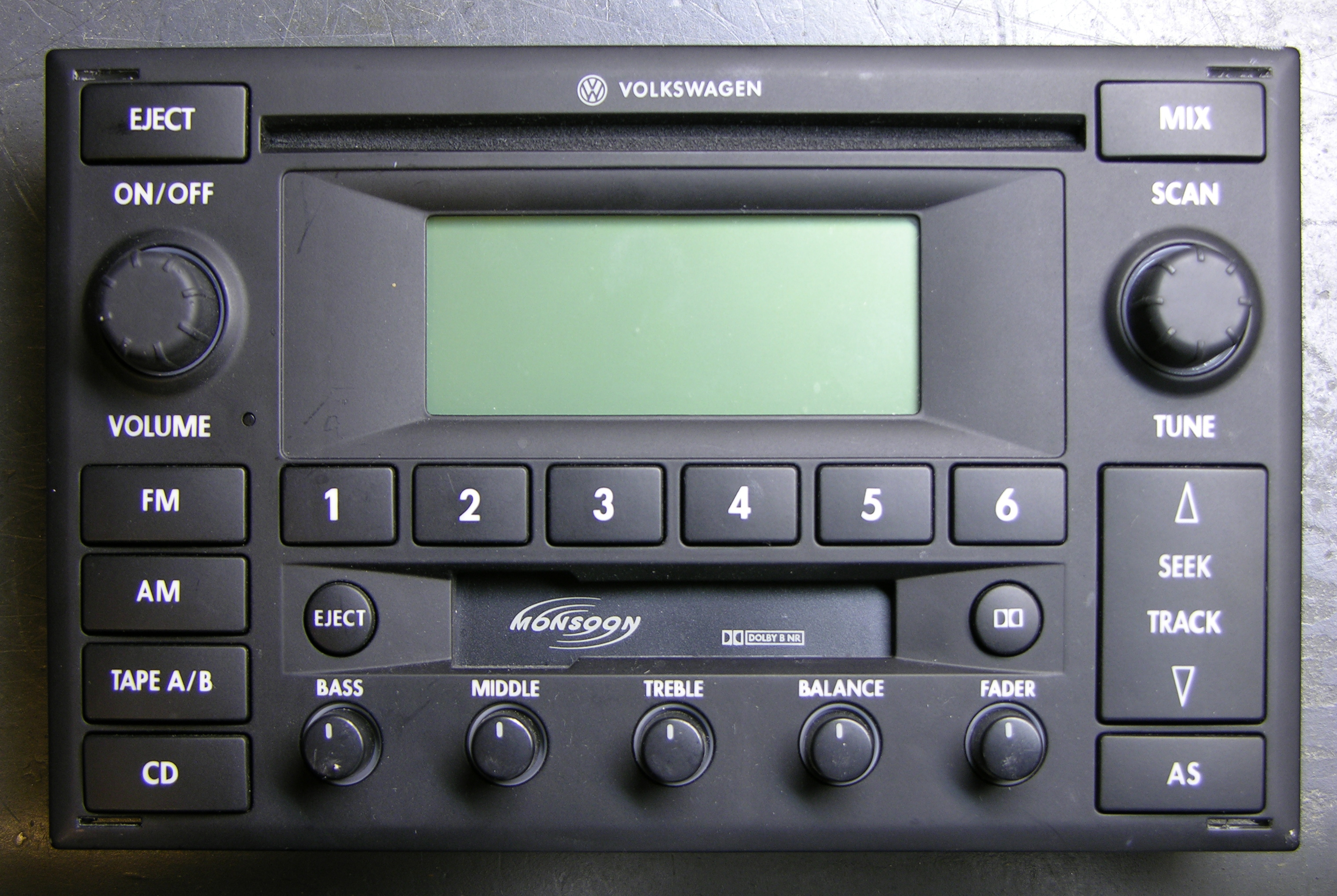
Here’s the front panel of a VW car stereo from Cort. If I recall the story correctly, it broke when their Jetta had a loose ground in the electrical system and everything went wacky. In any case, they replaced the stereo and gave me the old one. And thank goodness for that, because it has two lovely rotary encoders!
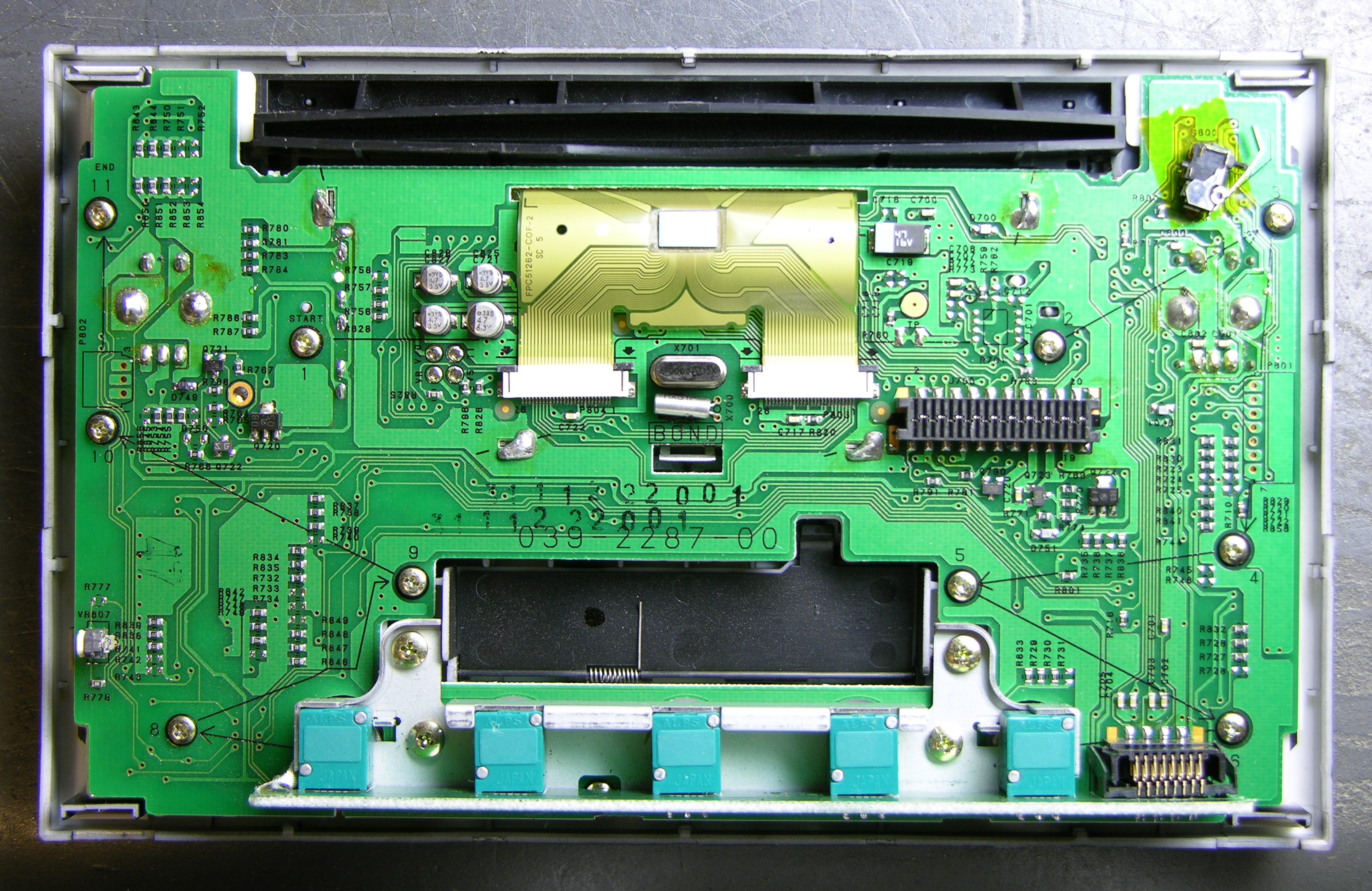
Here’s the circuit board side of the front panel. If you link to the large version of the picture, you’ll see something that really impressed me: The screws holding the PCB to the bezel are labeled “START,” 1 – 11, and “END,” with arrows pointing from each one to the next, presumably in torque order. Geez, you’d think these guys designed car parts, or something!

Here’s the front side of the PCB with the bezel and rubber buttons removed. On the large version of this picture, you can see that every front-panel button has two landing pads on the PCB, one on each end of the button. I’m developing some serious admiration for whoever designed this thing.
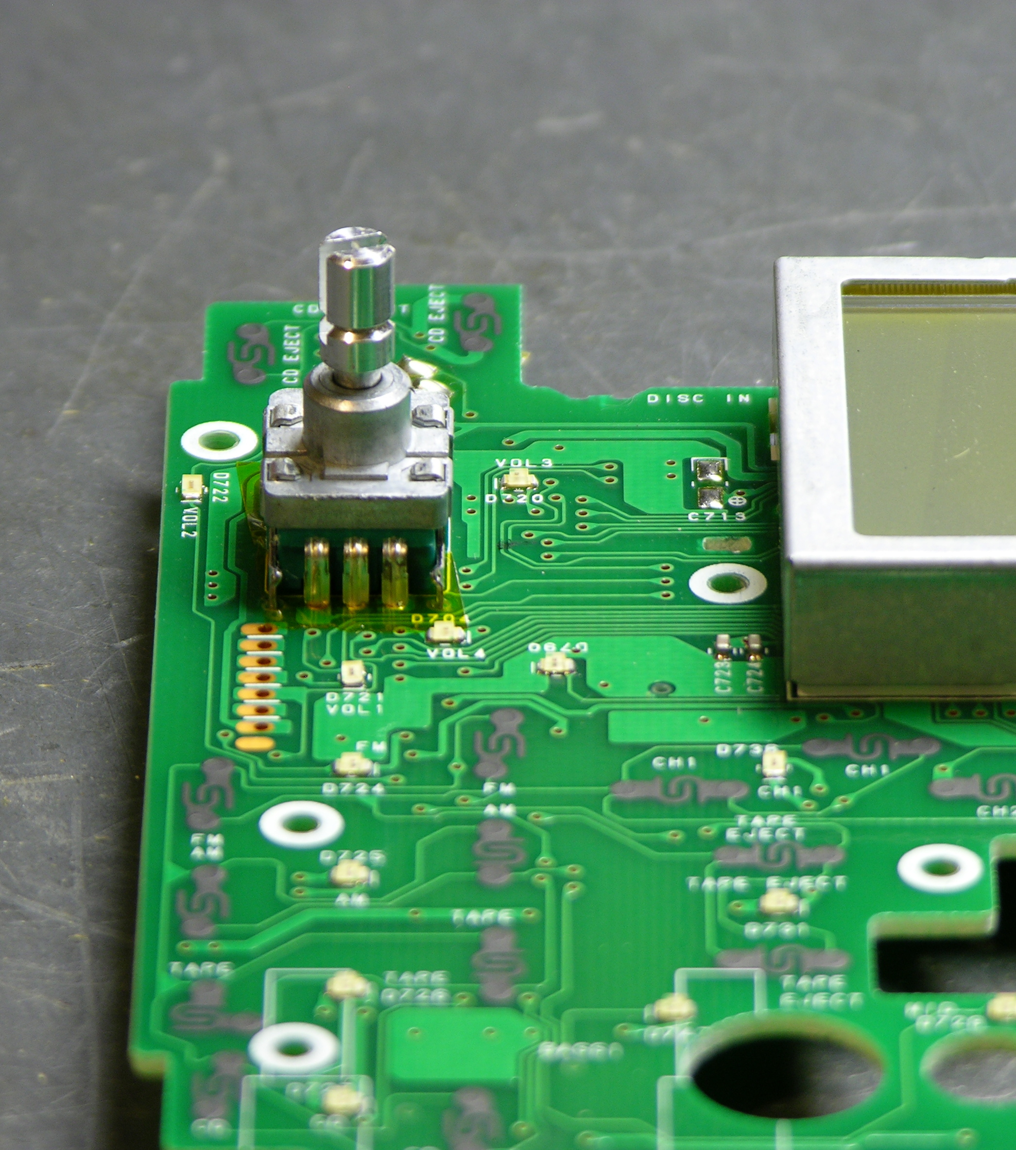
And at last, the object of my obsession.
A few minutes with the soldering iron and I had it extracted. It has two pins on the upper edge for the NO pushbutton action of the switch, and three pins on the lower edge for the common and quadrature connections.
Quadrature Encoding
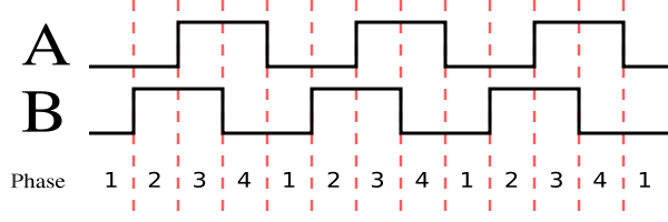
In the context of rotary sensors, quadrature encoding is the concept that two sensors are measuring the rotation of the same shaft, probably many events per revolution, but 90° out of phase from each other. Here the 90° refers to the staggering of the sensors’ output, not to 90° of rotation of the whole shaft.
As shown in this diagram from the Wikipedia article on rotary encoders, when you rotate the shaft one direction, the first output goes high, then the second goes high, then the first goes low, then the second goes low, etc. Rotating the shaft in the opposite direction causes the events to happen in reverse order. (This is the same scheme as driving a bipolar stepper motor, only sensing rotation rather than causing it.)
The combination of three pieces of information — which sensor changed state, which way it changed state, and what state the other sensor is in — is enough to determine the direction of rotation. And the period of successive changes in the same direction is enough to determine the rate of rotation (if you care). In my case, I’m going to want to know both — but more on that when I get this wired into the LED calculator.
Decoding My Rotary Encoder
This rotary encoder has detents, or “clicks” as you turn it, and I expected that one of the three quadrature pins would be common and the other two would alternate rising and falling as I turned the knob from detent to detent. In fact, I quickly discovered with my continuity meter that all three are connected together at one detent:

And none are connected at the next:
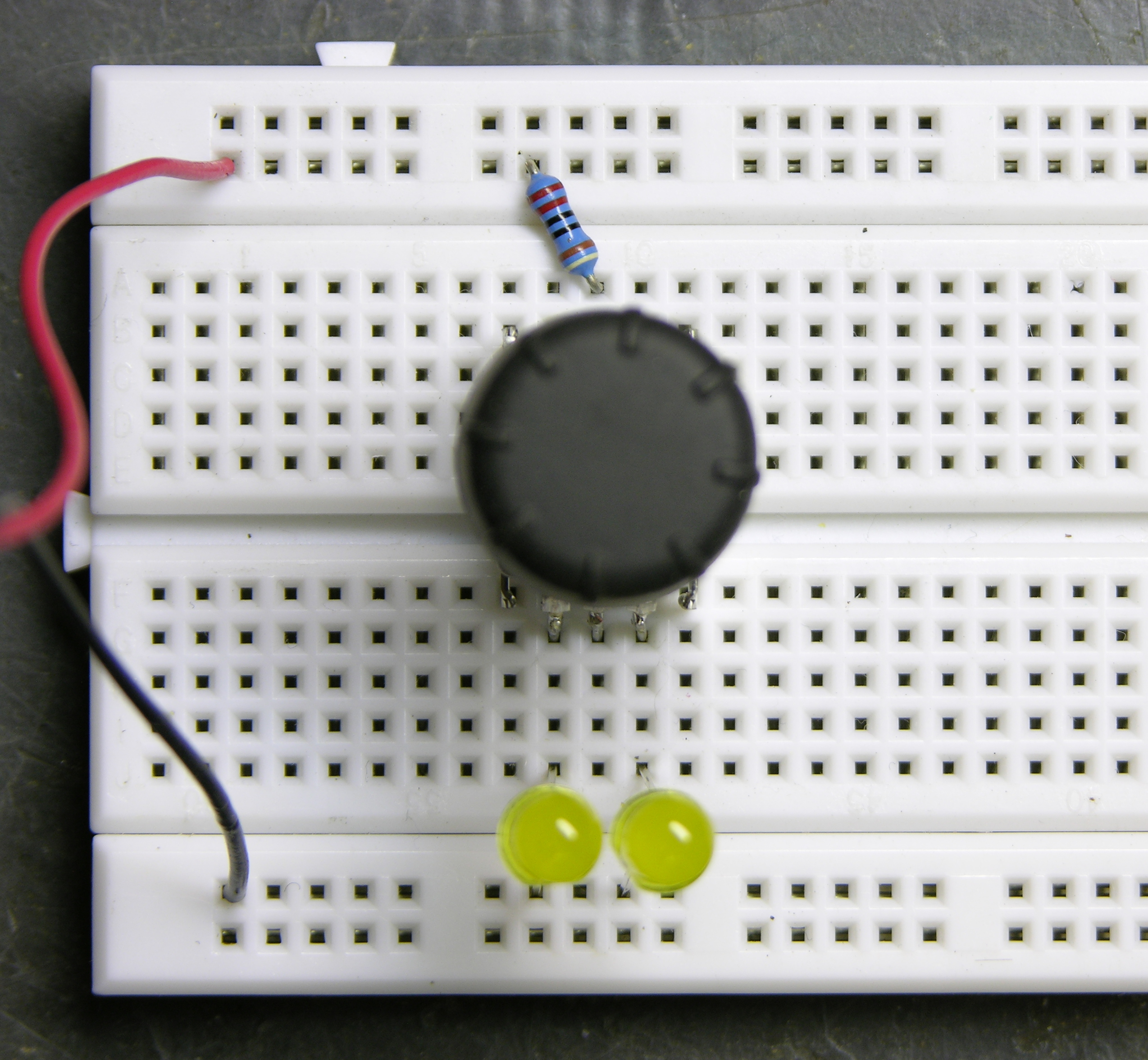
It turns out that the in-between transitions — 1 to 2 and 3 to 4 in the diagram above — happen between detents. That was hard to check for sure with the continuity checker and only two hands, which is why I breadboarded this.
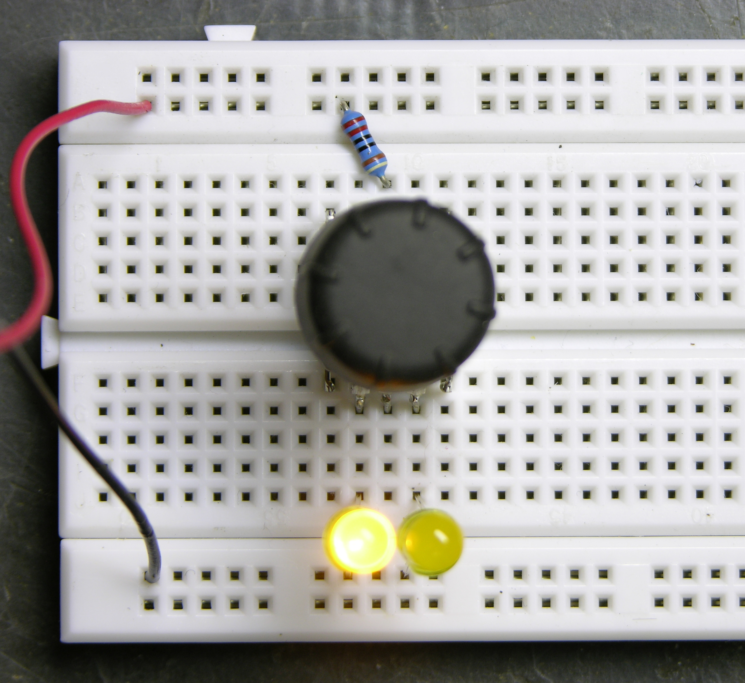
It’s much easier to turn to “tween” positions when it’s on the breadboard, and very easy to observe the quadrature output, which does indeed happen with the center pin common and the outer pins alternating.
And it turns out that having an extra quadrature state change between clicks is absolutely perfect for my planned application, because I want to know at each detent how fast the knob was just turned, even if it’s been untouched for a long time and only turned a single click. Having the “tween” transition gives me two transitions per detent, enough to measure rotational speed even for a one-click turn out of the blue.
More tomorrow on why I care about that, if it isn’t already obvious.
just for your information I bought 10 of these new ones on ebay here
http://cgi.ebay.com/12mm-Rotary-Encoder-Switch-With-Keyswitch-10pcs_W0QQitemZ230248142254QQihZ013QQcategoryZ67003QQcmdZViewItemQQ_trksidZp1713.m153.l1262
for really cheap price !
not worth destroying your VW radio…
If you still have the rest of the deck I might be interested in it for a project of mine.
Emailed Brent May 30.
Actually, instead of determining -which- sensor changed state, all you need is the fact of state change of any of them, current state of one and previous state of the other.
Say, you poll the channels and remember their states one cycle back. The channels are A, B and their values the moment before are A’ and B’.
Now if A=A’ and B=B’ – the wheel didn’t move or moved undetectably small amount. If any of them differs, A XOR B’ determines the direction of rotation.
s, there are several schemes for reading quadrature in half- and full-stepping modes, and I talk a little more about the details of decoding in yesterday’s LED Calculator with Rotary Quadrature Encoder for Target System Voltage Selection.
jeanyves: Thanks, great link. Those encoders are a good price – cheaper than Digi-key.ca even, including shipping costs.
Another simple how-to encoders work:
http://www.nutchip.com/progetti/encoder_led_en.htm
and a simple encoder-driven display:
http://www.nutchip.com/progetti/encoder_display_en.htm