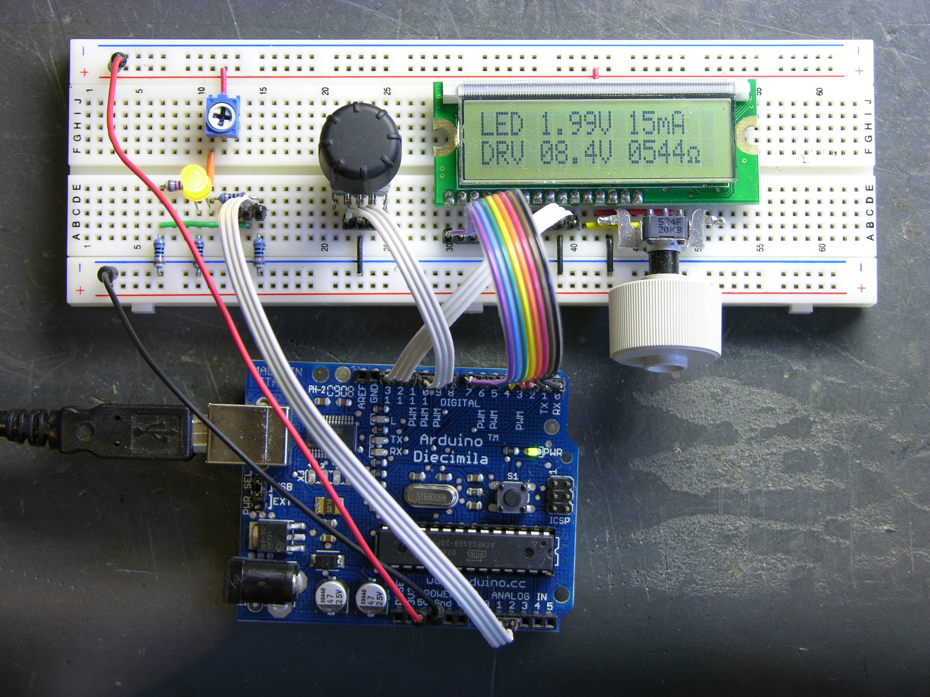
I’m still working on the LED calculator (original idea and most recent work) — I’ve finally got ’round to adding a rotary encoder to set the target system voltage. Now you can turn the potentiometer to set the LED brightness, turn the rotary encoder to set what voltage will be used in the ultimate LED circuit, and read the LED voltage, current, and current-limiting resistor values off the screen.
I also found the Ω in my LCD’s character matrix, so I tidied up the display a little.
And most significantly, I wrote an Arduino library for reading (multiple) quadrature encoders. The simple approach of polling them inside loop() was causing me to lose a lot of steps from the encoders; and the code to read them using hardware external interrupts (lower on the same page) only works on digital pins 2 and 3, so only supports one encoder if both pins are wired to interrupts for the highest resolution, or two if interrupting on a single pin and polling the other.
My Quadrature library uses the TIMER2 overflow interrupt service routine to poll multiple encoders rapidly and track the results, supporting as many encoders as you have room for on the digital pins. It also encapsulates all the dirty work into the library code, so using it is as simple as
#include "Quadrature.h"

Quadrature myencoder1(9, 10);  //  Connected to pins 9 and 10

loop() {
  x = myencoder1.position();
}
It still has some rough edges and it’s by no means perfect (more on that below), but it sure makes it easy to use rotary quadrature encoders. It’s available on a new Downloads page for anyone interested.
How It Works
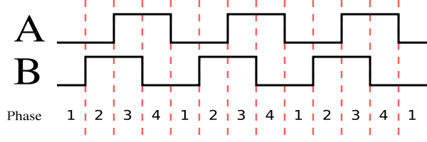
I’ve discussed previously how rotary quadrature encoders translate the rotation of a shaft into two out-of-phase digital signals from which you can derive both the direction and speed (or steps) of rotation. If you’re not familiar with quadrature encoding and care to follow along, it might be worth a detour to the earlier post to read up on that first.
Before diving into the code, let me say that although I’ve been programming in C for about 25 years, this is my first foray into C++; and everything I’ve figured out about it, I got out of books. I welcome advice on how to write better C++ code.
Decoder
The heart of decoding quadrature is processing transitions. There are various ways of thinking of the transitions, including “on a rising (or falling) edge of pin1, check whether pin2 is high or low to determine the direction” and “on a transition of pin1, XOR pin1 and pin2 to determine the direction.” Some of these don’t even react to every transition in the state diagram (courtesy Wikipedia’s rotary encoder article):
I wanted to be able to detect every transition for the highest possible resolution — but also have the flexibility to switch between “half-stepping” and “full-stepping” to change my resolution, depending on the demands of the application and the encoder. For example, the encoder I’m using in this project has two half steps per physical detent, so I want to be able to set it to read full steps (matching the physical “clicks”) instead of half steps.
It may not be the best way, but I encoded the state change information into a pair of arrays:
const int _half [4][4] = {
    { 0, -1, 1, 0 },            //  00 -> 10 is CW
    { 1, 0, 0, -1 },            //  01 -> 00 is CW
    { -1, 0, 0, 1 },            //  10 -> 11 is CW
    { 0, 1, -1, 0 }             //  11 -> 01 is CW
};

const int _full [4][4] = {
    { 0, 0, 0, 0 },             //  00 -> 10 is silent CW
    { 1, 0, 0, -1 },            //  01 -> 00 is CW
    { -1, 0, 0, 1 },            //  10 -> 11 is CW
    { 0, 0, 0, 0 }              //  11 -> 01 is silent CW
};
Then inside my service routine, I read the current encoder values into the quadbits variable, compare it to the previous value to see whether there’s a change [*], look up the <previous, current> pair in the full-step transition table to see what to add to / subtract from the position accumulator, and then save the current encoder values for the next round through the loop.
            if (quadbits != quad->_previous) {
                int position = quad->_position +
                        _full[quad->_previous][quadbits];
                . . .
                quad->_previous = quadbits;
* [This check isn't absolutely necessary since no-change is already encoded into the transition tables, but it shortcuts doing min/max checking if no changes have occurred.]
Right now, it’s hard-coded to use the _full[] transition table all the time, since that’s what I needed for this circuit, but it’ll be a simple matter to add another class function to select half- or full-stepping mode and choose the appropriate table here.
Calling the Decoder
Before moving it to an interrupt service routine, I tested calling the decoder function from inside the Arduino’s main loop. As I expected, when I had any other code in loop(), I lost significant numbers of steps when spinning the encoder rapidly by hand. In order to ensure the decoder was called fast enough to avoid losing steps, I moved its invocation into an interrupt service routine (ISR) for the TIMER2 overflow interrupt, which happens (in the Arduino by default) about 490 times per second.
The ISR is setup up by calling the macro ISR(<interrupt>):
ISR(TIMER2_OVF_vect) {
    Quadrature::isr();
}
The trick here is that the ISR isn’t called on a specific Quadrature object, and so doesn’t have access to the object’s private data (which pins to use, saved previous position, etc). I really didn’t want to expose all the private data as public for the ISR to access externally; and since the ISR isn’t (as far as I can tell) implemented as a function I couldn’t make it a friend function. Instead, I created a single public Quadrature::isr() function to perform the ISR tasks and called that function from the ISR.
Again, the ISR isn’t being called on a specific Quadrature object — it’s responsible for servicing all quadrature encoders that are connected. So the Quadrature::isr() function needs to have a registry of all Quadrature objects and loop through them, processing each in turn. My understanding is that the right C++ data structure for keeping that registry would be a vector; but I couldn’t find vector support in the Arduino C++ libraries, so I did it with an array. Blech.
Quadrature.h:
#define DIGITAL_PINS (13)
. . .
class Quadrature
{
    . . .
    private:
        . . .
        static Quadrature* _registry[DIGITAL_PINS];
        //static vector _registry;
};
Quadrature.cpp:
Quadrature * Quadrature::_registry[DIGITAL_PINS]; //vectorQuadrature::_registry; . . . Quadrature::Quadrature(int pin1, int pin2): _pin1(pin1), _pin2(pin2), _position(0), _min(0), _max(0), _usingmin(0), _usingmax(0) { . . . _registry[pin1] = this; //_registry.push_back(this); }
When each Quadrature object is created, I need to add it to the list of objects to be processed in the ISR. With a proper vector, I could push Quadrature object pointers onto the “list” upon creation and traverse the list in the ISR, servicing each encoder object in turn.
With an array, I should perhaps have kept a separate variable for the count of how many objects exist and put the object pointer into the next empty spot each time (much like using a vector), but instead resorted to stuffing the object pointer into the spot in the array defined by which pin is used for this encoder’s pin 1. I’m aware that the array never gets properly initialized the way it’s written now, and I’m very open to suggestions on improving this part.
So the remainder of Quadrature::isr() is a loop to iterate through however many Quadrature objects have been created and do the transition processing on each:
inline void Quadrature::isr(void) {
    int q;

    for (q = 0; q < DIGITAL_PINS; ++ q) {
        Quadrature *quad;

        if (_registry[q]) {
            quad = _registry[q];
            . . .
            //  transition code goes here
        }
    }
}
ISR Caveat
One last thing about the ISR: TIMER2 is used for Arduino PWM output, and my ISR doesn't interfere with that because the PWM is done in hardware and the ISR is done in software. However, my ISR will overwrite any ISR that may already have been attached to TIMER2, if the program is using multiple timer-driven libraries.
The last time I wrote ISRs was on the Apple ][ and Commodore-64, where the convention was to check the current interrupt vector before installing your ISR, stuff the current contents into your own code, and (if non-zero) jump to that location at the end of your ISR. That way if an ISR was already installed, you'd chain to it after your ISR code finished, and it would still be executed.
I can't quite see how to do that on the Arduino, though, at least not without rewriting the ISR() macro, and I'm not clear enough how chip-specific that macro is to be ready to tackle it. Another possibility would be to create an ISR registry system and persuade all ISR authors to use the ISR registry to insert their ISR into the registry-managed chain. Neither of these is able to force compatibility with non-cooperating code, though; and of course neither addresses the issue of different ISR-using libraries wanting to change the timer speed. Perhaps caveat library user really is the best that can be done.
Object Constructor
Here's the constructor to create a new object:
Quadrature::Quadrature(int pin1, int pin2):
    _pin1(pin1), _pin2(pin2), _position(0),
    _min(0), _max(0), _usingmin(0), _usingmax(0) {

    pinMode(pin1, INPUT);
    pinMode(pin2, INPUT);
    digitalWrite(pin1, HIGH);           //  activate internal pullups
    digitalWrite(pin2, HIGH);

    _previous = _readpins();            //  read initial position

    TIMSK2 |= (1 << TOIE2);             //  enable timer 2 overflow interrupt

    _registry[pin1] = this;
    //_registry.push_back(this);
}
The Quadrature::Quadrature() constructor uses an initialization list (I think I’m using the correct terminology) to initialize the values of most of the private variables. It then sets the two encoder pins as inputs and activates the internal pull-up resistors, reads in the initial encoder pin values, enables the TIMER2 interrupt, and (as seen before) registers this new object onto the list to process in the ISR.
Remaining Code
I haven’t touched on the minimum and maximum capabilities yet — you can call myencoder.minimum(foo) to set the minimum value of the encoder’s position to foo and myencoder.maximum(bar) to set the maximum to bar. You can also call oldmin = myencoder.minimum() to read and save the current minimum setting, with a corresponding function for reading the max; and you can call myencoder.nominimum() to turn off minimum (or maximum) processing if you don’t want it in a particular section of code.
I’m trying to facilitate a program using an encoder for multiple functions — for example, first selecting a mode (“Audio Function”), then selecting a parameter (“Balance”), then selecting a value for that parameter (-5 to 5). Each of these may require different minima and maxima for its list, all operating at different times on the same encoder object.
Most of the rest of the code is housekeeping. It’s a bit long to paste the whole thing in here; but if you’re interested in looking it over and offering improvements, download a copy, look over Quadrature.h and Quadrature.cpp, and post comments below.
Using the Quadrature Library
Encapsulating code into libraries makes using that functionality so much easier; and encapsulating multiple encoders into objects is a really good use for object-oriented programming. The pertinent sections of my LED calculator code have simplified to this:
#include "Quadrature.h"
Quadrature supply(8, 10);

. . .

void setup() {
  . . .
  supply.minimum(0);
  supply.maximum(120);
  supply.position(50);
}

void loop() {
  . . .
  resistor = (float) supply.position() / 10 / led_current;
  . . .
}
I’m dividing the rotary encoder’s value by 10 to serve .1V increments, and initializing it to run from 0-120 (0-12V) and to start at 50 (5.0V). I’m also thinking about creating a setup menu for the LED calculator user to program in their preferred minimum, default, and maximum supply voltages for the target system, and saving those in the Arduino’s internal EEPROM.
Future Enhancements
Enhancements to the Quadrature library:
- Clean up the
_registry[]array code — make it work more like a vector, as discussed above. - Support changing between half- and full-step modes.
- Add an “acceleration” mode that works like mouse drivers — increment/decrement with a larger step size when you’re turning the encoder fast. (Right now, it takes me multiple turns to get from 5V to 12V. It should take a single fast turn to get close, and some slow fine-tuning to dial in the exact desired value.)
- Add a function to change the timer speed, hence the frequency of checking the encoder in the ISR. Right now the code works well for hand-driven rotary encoders, but would drop steps horribly for encoders attached to motor shafts, wheels, etc.
- Create a subclass to return speed and direction, rather than position?
Enhancements to the voltage-selection code in the LED calculator:
- Allow the user to change the minimum, default, and maximum target voltages, as mentioned above.
- Allow the user to program in a set of favorite voltages (e.g. 3.3V, 5.0V, and 12.0V) and make the rotary encoder select from the list rather than dialing in arbitrary voltages?
LED Calculator Next Steps
I have an enclosure for the calculator that I’m not thrilled about (it’s taller than I like) but which will work, and an LCD that fits the case. I need to order rotary encoders from Digi-Key so I can build an exact prototype of what I want to offer kits for, and then I’m ready to lay out the PCB and make one!
may be this simple program from parallax quite old will do the job much easier ????
this was written for a pic assembler but is quite simple to read and understand.
; PROGRAM: Read Rotary Encoder (RD_ENCDR.SRC)
; This program accepts input from a rotary encoder through bits RA.0 and RA.1,
; determines the direction of rotation, and increments or decrements a counter
; appropriately. It displays the hexadecimal contents of the four-bit counter on a
; seven-segment LED display connected to port RB.
encoder = ra
display = rb
; Variable storage above special-purpose registers.
org 8
temp ds 1
counter ds 1
old ds 1
new ds 1
; Remember to change device info when programming a different PIC.
device pic16c54,rc_osc,wdt_off,protect_off
reset start
; Set starting point in program ROM to zero.
org 0
start mov !rb, #0 ; Set rb to output.
mov !ra, #255 ; Set ra to input.
clr counter
mov old, encoder
and old, #00000011b
:loop call chk_encoder
mov w, counter
call sevenseg
mov display, w
goto :loop
chk_encoder mov new, encoder ; Get latest state of input bits.
and new, #00000011b ; Strip off all but the encoder bits.
mov temp, new
xor temp, old ; Is new = old?
jz :return ; If so, return without changing
; counter.
clc ; Clear carry in preparation for
; rotate-left instruction.
rl old ; Move old to the left to align old.0
; with new.1.
xor old, new
jb old.1, :up ; If the XOR resut is 1, increment
; counter, otherwise decrement.
:down dec counter
skip
:up inc counter
and counter, #00001111b
mov old,new
:return ret
sevenseg jmp pc+w ; display lookup table
retw 126, 48, 109, 121, 51, 91, 95, 112
retw 127, 115, 119, 31, 78, 61, 79, 71
jeanyves, that code is equivalent to what I mention won’t work on the Arduino if the Arduino is doing anything else. It’s a nearly exact translation of the code I link to early on from the Arduino Playground.
I agree that it’s trivially easy to write a tight loop to monitor a single encoder and do nothing else, but that code (1) becomes more complex quickly if you want to run multiple encoders, and (2) fails quickly if you need to perform other tasks of indeterminate duration inside the main loop. The more complex and demanding environment drives the need for a more complex and robust solution.
Keith: Thanks for putting this library together! You’ve done the community a great service.
Uh, Tom, I was expecting to get flamed for (A) underrepresenting someone’s favorite decoding technique, (B) leaving the timer overflow interrupt at the default 490Hz, (C) posting code that won’t work (as-is) with encoders on motors, and (D) all kinds of other random things. You’re not supposed to say thank-you.
I think we’re all missing the most important point here, that ribbon cable is trippy. I can never make layouts that clean, but it’s not for lack of trying .
.
Brenden, I think you’re being a little tongue in cheek. But I have to say that even though I’ve always been pretty meticulous about breadboarding with wires cut to length, I’m really happy with the way things are turning out now that I’ve made myself pluggable ribbon cables for going between boards or taking a whole I/O bus from one section of a board to another.
Grab some old ribbon cable, cut it to length and width, strip and tin the ends, solder to a male header, and don’t forget to mark pin 1 at both ends. For the deluxe version, coat the whole solder joint area with epoxy or hot glue to provide strain relief and a bit of a handle for inserting and removing the pins in the breadboards, and it’s a pretty slick system. Way better than a gazillion long jumper wires.
And always prep a few more of whatever you’re making than you need right now. You’ll thank yourself later.
“Trippy,” huh?
Hello Keith:
When I try to compile the program I have this error:
I’m using the latest Arduino Diecimilla and avr library
In file included from /home/pvilas/utils/arduino-0013/hardware/cores/arduino/WProgram.h:4,
/usr/lib/gcc/avr/4.2.2/../../../../avr/include/stdlib.h:116: error: expected unqualified-id before ‘int’
/usr/lib/gcc/avr/4.2.2/../../../../avr/include/stdlib.h:116: error: expected `)’ before ‘int’
/usr/lib/gcc/avr/4.2.2/../../../../avr/include/stdlib.h:116: error: expected `)’ before ‘int’
Thank you to share your code.
Thanks Keith for your work- this library is very useful.
One question: How does the library need to be edited for half-step mode? I assume this is what I need – running your example code I am getting inc/dec of 2 every detent on my encoders.
Thanks Again!
Mark, half-stepping mode is actually going to double the number of increments/decrements you get (unless I’m all muzzy-headed this morning). To see that, go into hardware/libraries/Quadrature/ and change line 84 of Quadrature.cpp from
_full[quad->_previous][quadbits];to_half[quad->_previous][quadbits];, then delete Quadrature.o and recompile your Arduino program (which will automatically recompile the library), and I believe you’ll get twice as many steps.What I found is that most of the commercial rotary encoders I’ve got use two full steps per detent. I’m sure it makes sense somehow, but I’m not quite sure how.
What I had to do in my most significant Arduino program that used Quadrature was write
selected = quad.position() / 2;, which works but is obviously not desirable. The long-term fix will be to add a modulus to the Quadrature code that you can use to set steps per increment for your particular encoder.By the way, can you tell me which Arduino programming environment version you’re using? See Pere’s note above — I get the same result when trying to use Quadrature with Arduino 0013, and I haven’t figured out why yet.
Thanks. I figured out for my encoder (CTS brand I believe) I need to use this scheme:
{ 0, 0, 0, 0 },
{ 1, 0, 0, 0 },
{ -1, 0, 0, 0 },
{ 0, 0, 0, 0 }
And as far as the errors, several libraries are having the same problem. I guess some definitions in Wiring.h conflict with the standard C headers. Adding this to sketches after any #include’s fixes it:
#undef int
#undef abs
#undef double
#undef float
#undef round
Source: http://www.arduino.cc/cgi-bin/yabb2/YaBB.pl?num=1222985221/2
It works!.
Thanks Mark!
Here is a simple solution for implementing ‘acceleration’ for this great library. My situation was that I needed to send an increment/decrement number to software, not the encoder ‘position count’ for 4 encoders.
My solution was to reset the encoders to zero after so many times through loop(). So if I bump the encoder 1 notch during 20 repetitions of loop(), 1 is sent to software. If I spin it fast the encoder counter accumulates higher, sending these values every time through loop(). Sort of a dumb way to implement, but it solved two problems easily for me (sending inc/dec count, accelerating the knob) and works flawlessly.
At the top of loop() I have:
if (encoderReset==20)
{
encoder1.position(0);
encoder2.position(0);
encoder3.position(0);
encoder4.position(0);
encoderReset=0;
}
and at the end of loop():
encoderReset++;
How about using int8_t for the transition matrix? That’ll save 16 bytes of ram …
Your Quad. library is great, thanks so much for sharing and documenting!
I would like to know if you have any ideas on implementing ‘acceleration’ for this great library?
Ben, interesting question! I hadn’t thought about it, but it’s a good idea.
I need a project in which I need acceleration, and then I’ll program it in.
Ben –
The Arduino functions millis() and micros() should be able to get you acceleration. These functions give you milliseconds or microseconds elapsed. If you take the time between interrupts, faster rotation will give you shorter time periods and slower rotation will give longer time periods. It’s been a while since I examined Keith’s code, but somewhere there is an interrupt service routine that could have this addition pretty easily.
http://www.arduino.cc/en/Reference/Millis
http://arduino.cc/en/Reference/Micros
Keith –
I thought you might like to see how your library helped me out on a project! It uses 8 rotary encoders that would otherwise be too much for the Arduino:
http://mayhewlabs.com/joycontrol
Thanks for your work!
Mark, the quadrature library does its interesting bits inside timer 2 interrupt. It’s been a while since I examined the millis() code, but it almost seems like there was some gotcha about calling it inside an ISR???
In any case, what you describe is exactly the right idea; millis() or micros() or manually checking whatever register the Arduino is using to track time is just an implementation detail.
Mark, that’s awesome; glad the library was useful and thanks for the note!
I already hacked some acceleration code into your library.
In the cpp file:
quad->_timer_count++;
if ( quad->_timer_count – quad->_last_change > quad->_acc_time && quadbits != quad->_previous) {
int position = quad->_position +
_full[quad->_previous][quadbits];
if ( quad->_timer_count – quad->_last_change _acc_time && quadbits != quad->_previous )
{
position = quad->_position +
(quad->_accelerate * _full[quad->_previous][quadbits]);
}
and at the end:
quad->_last_change=quad->_timer_count;
}
I didn’t have time today to implement an interface to set the used timeout _acc_time and the acceleration factor
Maybe the acceleration should be depending on how much change there is in the used interval (more positional changes -> more acceleration )
Great library – thanks!
As a future feature, you might want to add in the ability to tell if the knob has been pressed down while turning or not (assuming that you have the knobs like I have with that ability).
Great library, very easy to work with. Also works pretty reliably with my ALPS encoder.
Two things though: 1) To get it to compile, math.h had to be included first, so I added an #include “math.h” in Quadrature.h _before_ including WConstants.h. Works great now, but took me a moment to figure it out.
2) With the Bourns encoder, position() changes by at least two with every click on the encoder. It would be nice if the library could “half the steps” or so for these types of encoders.
Nonetheless: Great work, thanks
hey, thank you very much for your great work, your library really helped me to get my rotary encoders to work!
I was just wondering if it’s me or if it’s the library that I cant use the decoders on digital pins 14 – 19 (aka analog 0 – 5) on an arduino? I’d like to so because I’m planning on adding some wireless function and would need the other digital pins to interface with the wireless hardware.
Max, I recall having some trouble getting it to work on some of the higher dedicated digital pins — 12 or 13, perhaps — and not having figured out why.
For the analog pins, are you listing their digital pin numbers as
A0,A1, etc.? I don’t know of a reason offhand that that wouldn’t work.Quadrature.h:
#define DIGITAL_PINS (13)
Increase the value here to 20 and you can use all pins
Ben, obvious fix that I’d forgotten! Thanks!
Btw…pin 13 will probably give some problems because of the LED on this port. I Solved this by removing the led from the arduino
Is that sketch correct for using with ALPS rotary encoder ?
link : http://fraph.free.fr/arduino/ArduinoEncoder.jpg
ref of alps rotary encoder :
http://fraph.free.fr/arduino/alps.pdf
Thanks.
Sometime, the encoder sends false information and the values move up or down without any reason. Can you help me about this point.
I use 10 rotary encoders with an Arduino mega.
and use Digital input from 32 to 49 and 29 and 31.
Raph, I don’t know — I don’t have that encoder, so I haven’t had an opportunity to test it myself. I also haven’t tested the library on the Arduino Mega yet; perhaps there are compatibility problems.
Have you checked the encoder with an oscilloscope to find out whether the false triggers are coming from the encoder or from the software? Perhaps the encoding traces are slightly misaligned with the detents and you really are getting false signals from the encoder rather than from the software.
I don’t get an oscilloscope. Alps are really good rotary, we can find them in a lot of audio desk mixer.
The question is, must I have to provide 5v to A and B pins thru 10k resistor or plug it directly to the digital input of arduino ? (considering the datasheet of alps).
Arduino mega works very well and with no trouble.
Hello. i am using this great library on my Arduino Mega. Works perfect but i want to work with Arduino Due atsam3x8e mcu. i cant uploat to Arduino Due i got some arrors because different Timer codes. is it possible to adapt Arduino Due ?