The Project
My friend Joel has a computer numerically controlled (CNC) drilling machine that he built from a mail-order unpopulated circuit board and a set of plans. Its table holds materials up to about 10″ x 14″, and I go over to use it any time I need to drill a circuit board. It’s not terribly inconvenient to use his, and it’s always a nice excuse to visit with him while we’re setting it up and letting it run–but I’ve wanted my own for as long as I can remember. They’re just cool.
There are lots of descriptions of and plans for CNC drilling machines on the Web, so I won’t go into a lot of detail. The basic idea for this model, though, is that a drill is suspended in place above a table that slides around to position the workpiece. The table is positioned by long screws (all-thread) turned by stepper motors, which are motors that move small increments (steps) in response to an input signal, rather than running freely. Each step is a small fraction of a complete rotation, and coupled with the worm-drive effect of the lead screw allows for very precise positioning of the workpiece–easily 1/1000″, and often 1/8000″. (Of course, mechanical issues like backlash do intrude, but 1/1000″ doesn’t seem to be terribly hard to achieve.)
The Motors
So . . . I want to build my own CNC drilling/milling machine, and since I do electronics bottom-up, the project starts with the motors. And boy, do I have motors. I have these giant steppers out of heavy-duty wide-carriage impact printers from a former employer just begging to be used.
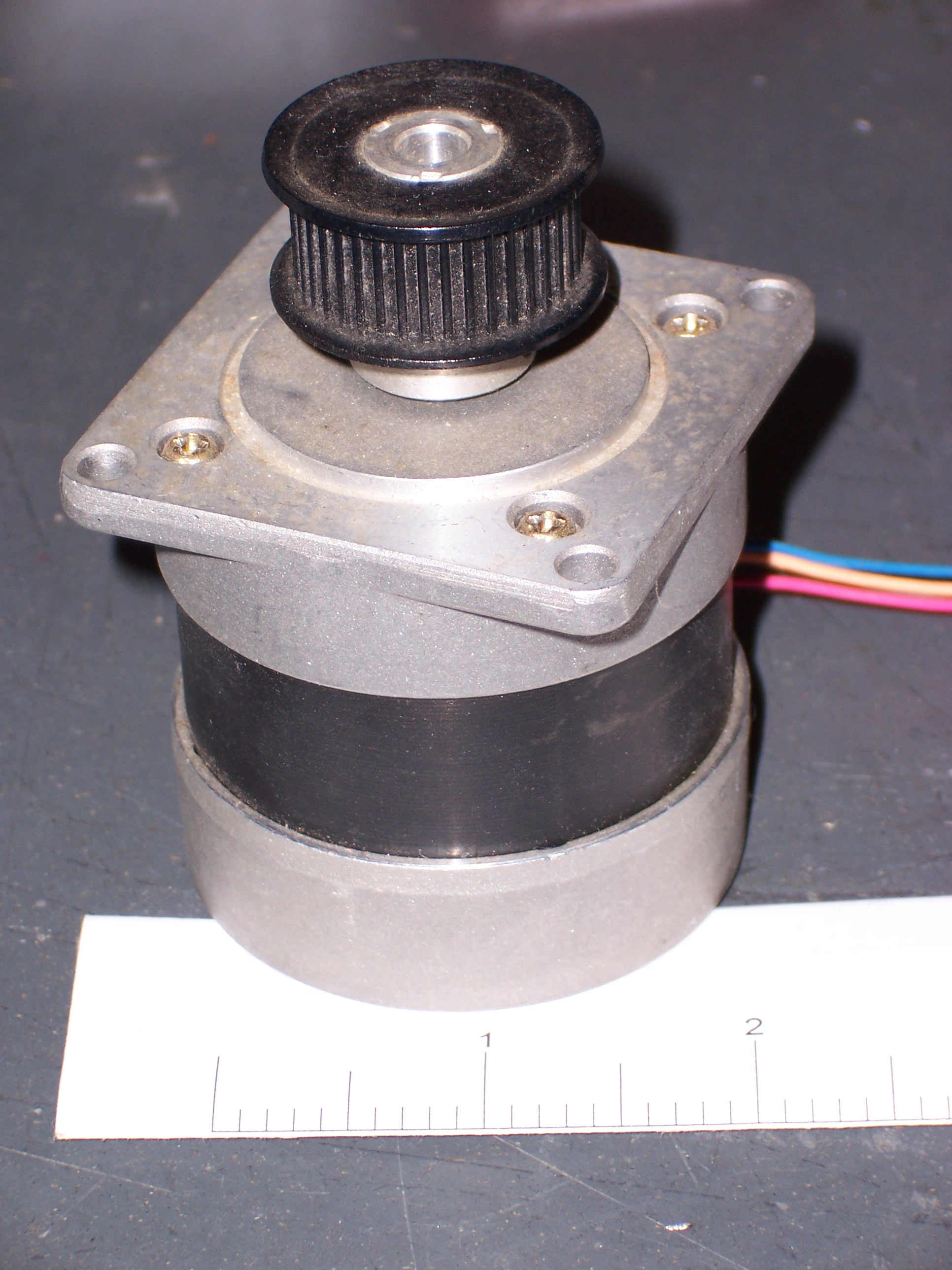
If you look carefully, you can see the ruler underneath the motor–it’s a good 2″ in diameter. Pretty heavy, too.
As we wrapped up our TechArt installation, my thoughts have been returning to these motors, and wondering what it would take to start building drivers for them. This weekend, in between community orchestra rehearsals, I sat down with one of the motors and started making notes. Here are the specs from the sticker on the back side:
PULSE MOTOR
TYPE PJ55E1U97AA / Phase: 2.5
Ω / Phase: 0.85Nippon Pulsemotor Co Ltd
Uh, .85Ω per phase? Are they kidding??? That’s an insanely low coil impedance compared to what I’m used to on traditional motors. I can see already this is going to be a challenge.
The Coils
The first thing to do with an unknown stepper motor is figure out the coil wiring. Steppers have multiple coils, each determining either one or two rotor positions, and each with an external wire or pair. From the steppers I’ve played with, four wires generally means two coils each powered in alternating directions, five wires is one common plus four unidirectional coil connections, and six wires is three unidirectional coils. This motor has four, so it was a simple check with an ohmmeter to determine which wires go to which coils.
Red to black: 1.3Ω
Orange to blue: 1.2ΩInternal resistance of meter (shorting probes together): .3Ω
Variation due to probe placement and pressure against pins: up to .2Ω
So yeah, that’s pretty much .85Ω per coil. Wow.
The label says 2.5A per coil. To get 2.5A current, 2.5A * 1Ω = 2.5V and 2.5A * .85Ω ≡ 2.1V. That’s a really low coil voltage, given some assumptions I’ve already made about the drive circuitry, so I can tell that’s going to be a challenge.
Finally, I hooked wires to my bench power supply and touched them to the coil wires, just to watch the rotor move. In that very unscientific experiment, it looked like the stepping behavior (speed and impact of single steps) was about the same when using a 5V supply as when using a 2.5V supply. That gave me hope that I might be able to fudge on the details and use a higher coil voltage than nominal–although I don’t want to heat up the motor and melt the coils during intense use.
The step pattern I tried moved the motor CCW: black/red, blue/orange, red/black, orange/blue.
There are actually two different configurations to a four wire motor internally, as they actually always have four coils not two as it would appear at first. One way has series pairs and the other paralleled pairs. One obviously requires twice the current to operate than the other, but at half the inductance, for the end result of shorter rise time and faster stepping. Obviously the other delivers twice the coil strength per amp, but won’t rise and therefore step as fast at the same voltages.
There are two other configs you will run across, six and eight wire. With this size motor the six wire units you will find won’t have three coils – they have four just like the bipolars, but each pair has an added center tap. If they have eight, the four coils have taps at both ends, the reason being you can then chose to wire them externally for either of the two common bipolar modes based on your needs, and a couple of other less common ways as well. The oddball five wires you will find use different types of drive logic entirely, and there are several very different types. The one you have seen, one that actually has five coils all connected to each other in a ring with no common at all, and one with five coils arranged in a star config joined at the center. I have no idea how those work, but I guess someone figured it out….
While the 2.1v number you calculated is correct, the steppers won’t actually run at that. The voltage for steppers is a bit confusing, as they really need a constant current not a constant voltage. The driver will act to limit current for you, and the best voltage for those would probably actually be around 24v-36v depending on what the max the driver chip you are using will handle. Usually its 10-20 times rated voltage to get any reasonable rise time or else you either can’t step rapidly enough to be of any use, or you will be stepping way before the coil gets to rise to any strength. Remember that on decel it will act as a generator and feedback a few volts, so don’t go quite all the way to the drive chips Vmax or you will magic smoke the drive on decel. Things you don’t normally think of working with the smaller steppers on electronics! Full size motion control is a bit different of an animal.
Eric, you have the disadvantage of coming across this post a long time after it was written, during which time I’ve written quite a bit more.
In particular, I switched to using an A3977 stepper controller that uses pulse-duration modulation current control, and increased the step rate almost five-fold from 500 to 2300 steps per second using a high supply voltage as you describe.