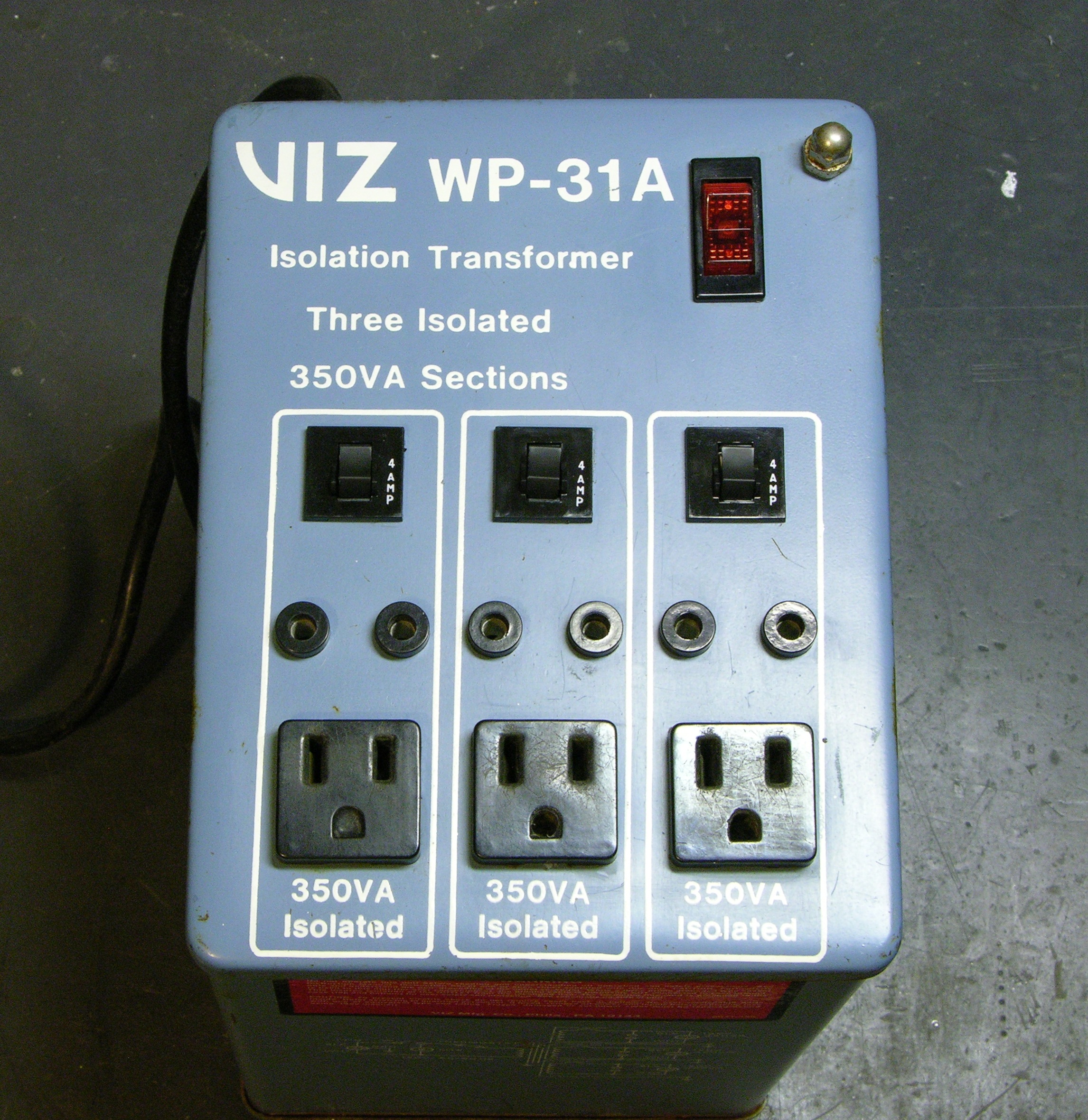
An isolation transformer, as used in electronics testing and repair, is a line-powered transformer with 1:1 windings (e.g. in the US, ~110VAC in, ~110VAC out). It’s used to isolate a circuit under test from line power for two main reasons (that I know of):
- With line-powered equipment, if you were to touch a hot part of the AC side of the circuit while it was plugged straight into wall power, you could become a return path to ground and get electrocuted.
The transformer isolates it from the rest of the world, so your risk is reduced to becoming a return path within the circuit, and you’re not at risk of conducting from any single point to ground. This doesn’t eliminate the need for care, but it reduces the hazard. - Some line-powered circuits use a local ground that is something other than earth. (The mixer power supply I repaired recently uses a local ground on its primary side that’s at about -85VDC with respect to earth.)
If you want to use test equipment (oscilloscope, line-powered meter, etc.) to probe the circuit, you need to connect the equipment’s ground to the circuit’s ground. If they’re both line-powered and the circuit uses something other than earth as ground and you connect the equipment’s real-earth-ground to the circuit’s specifically-non-earth-”ground,” you’ll create a short circuit fatal to one or both pieces of equipment.
The isolation transformer “floats” the circuit so its local ground is safe to connect to your test equipment’s ground. Of course, this potentially reintroduces the shock-to-earth hazard mentioned above, during the time you have the grounds connected for testing.
While repairing the aforementioned power supply, I dug my isolation transformer out of the basement. I had acquired it grungy and broken (and this is odd, but I don’t remember whether I got it from Slim or purchased it at Lloyd’s) and it had been through a basement flood, so it needed rework before I could use it. I’ve just polished off the last of the repairs.
Rediscovering the Symptoms
I recalled that the transformer hadn’t worked when I got it, and that I hadn’t done any further exploration at the time. Knowing it had stood in 1/2″ of floodwater, I began my investigation by drilling out the rivets holding the base onto the bottom of the case and trying to pry off the base, so I could inspect for new damage before going back to look for old. At first I thought the case bottom was rusted on, but by now I’ve decided that it’s probably held in place by potting compound and the rivets became superfluous once original assembly was completed.
I drilled out the rivets on the top and got it open. Actually, first I cleaned a bunch of grime off of the top so I wouldn’t have to keep touching it. Yech.
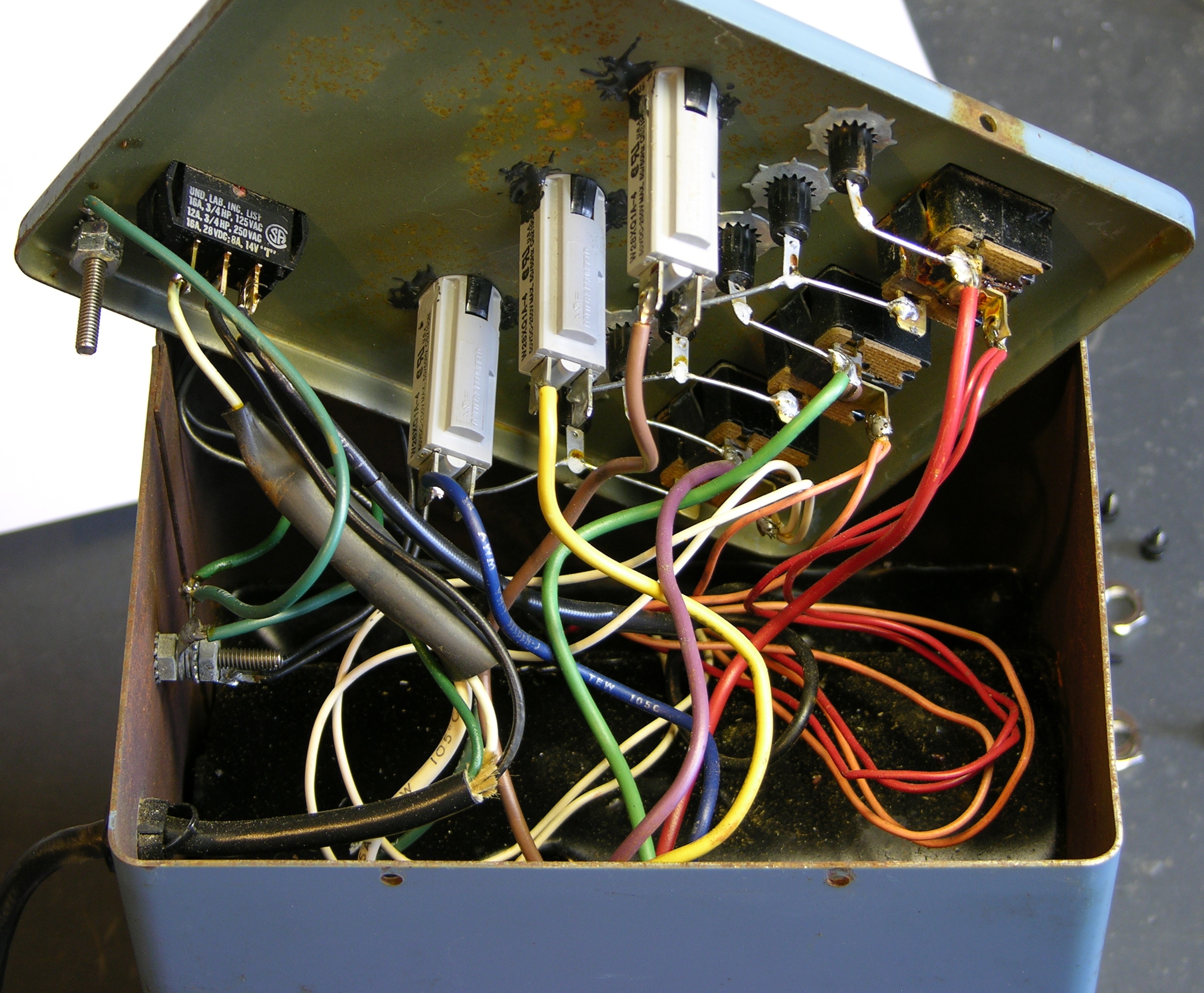
The transformer assembly has panel-mounted switches, receps, and circuit breakers. And lots of pretty, colored wires.
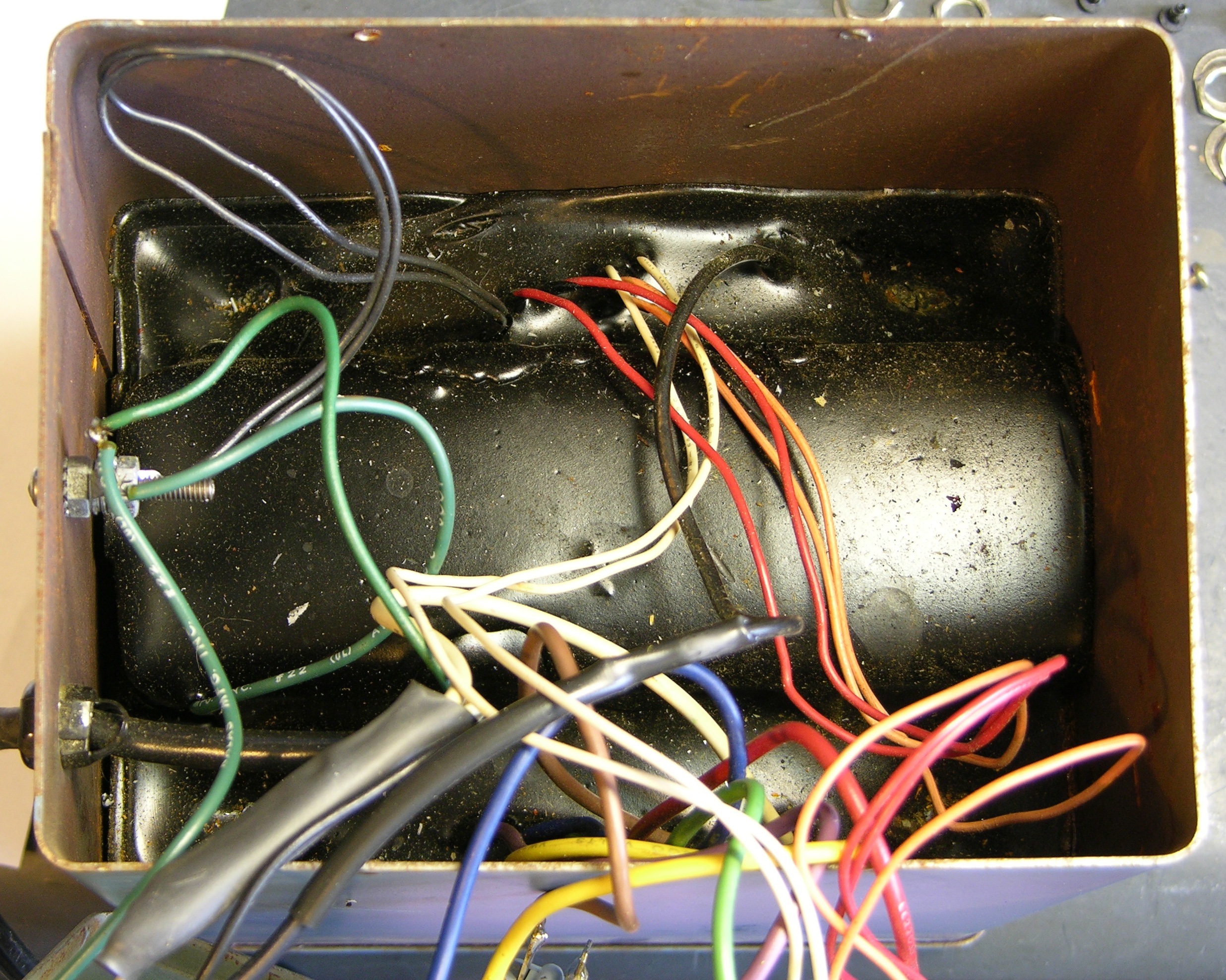
The transformer proper is in the bottom of the case, potted in a relatively soft, waxy black material that doesn’t smell very good (or maybe that’s the floodwater).
Because had only been in shallow water, and because the potting compound appears to be water-resistant so I don’t think the windings were damaged, and because all of the interesting bits are at the top where they shouldn’t have got wet, and because everything looked visually okay, I plugged it in to refresh my memory on what was wrong.
No power out of the receps, that’s what was wrong.
Damaged Circuit Breakers
I used a continuity tester to locate where the circuit was open. I could have done this by turning on the power and using a voltmeter, but short wires make the top panel balance pretty precariously when it’s open. Besides, why mess around near 110V when there are equally easy ways to do the job?
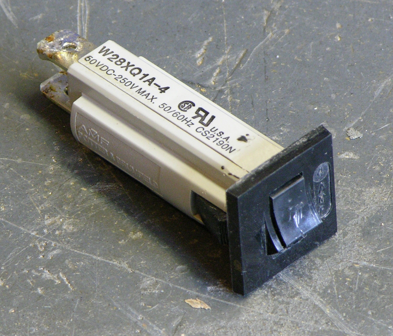
It took but a moment to discover that the circuit breakers were the problem, and a few more moments to desolder one, unclip it, and remove it for inspection.
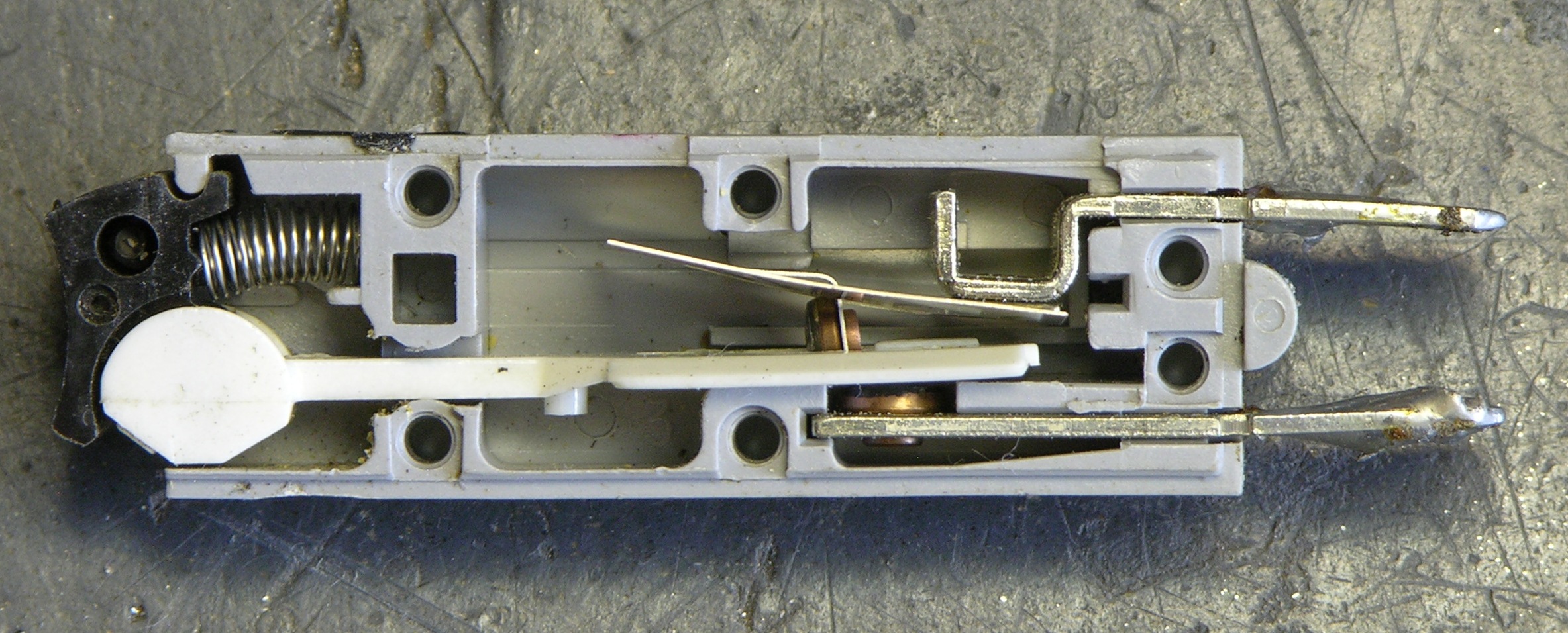
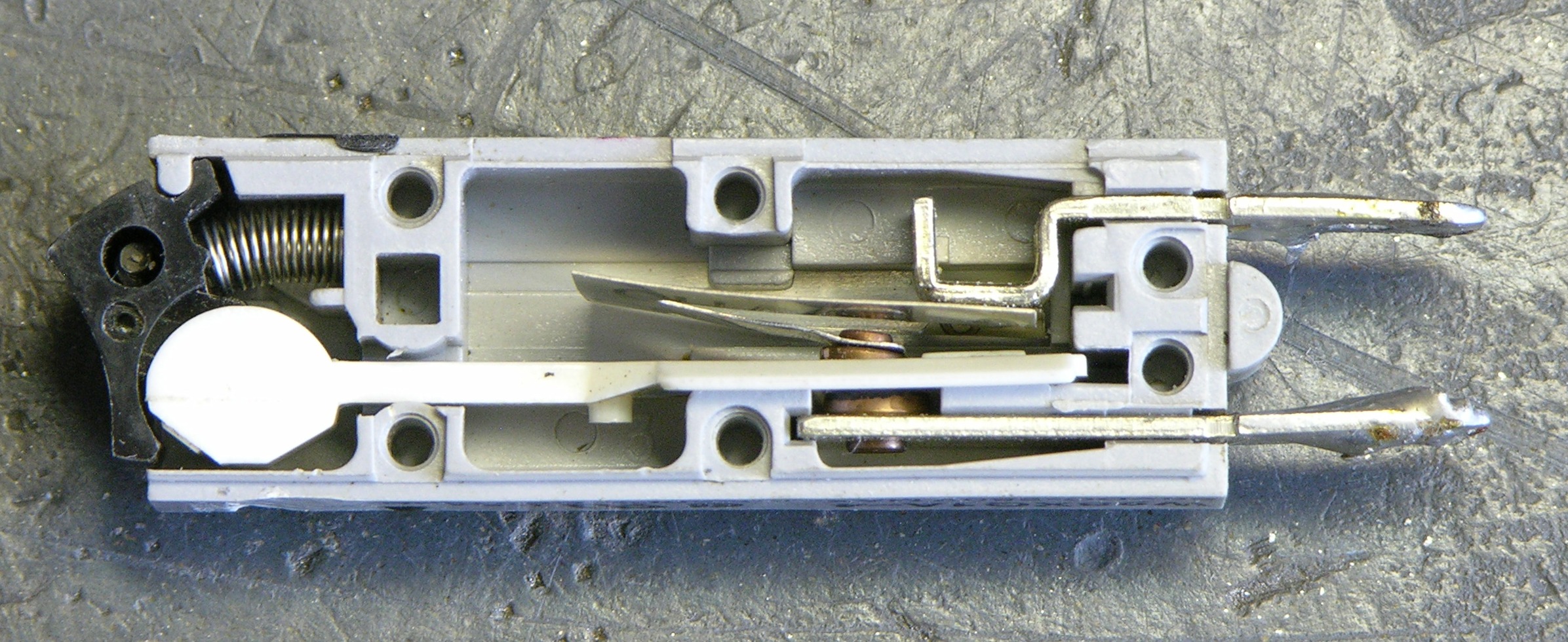
What on earth.
The breaker has a leaf spring (in about the center) that obviously is supposed to make contact with the lower terminal through a “window” in the white plastic strip under normal conditions. The leaf spring must be bimetallic, and during an overload condition it presumably heats and pulls away from the lower contact.
Once the spring terminal exits the plastic strip’s window, the strip slides out (it’s hinge-attached to the black, spring-loaded piece), blocking the spring terminal from returning to its resting position and making contact once it cools. Pressing the black button face pushes the strip back into position, allowing the leaf spring terminal to return to rest and make contact with the lower terminal again.
So how is it possible for the leaf spring’s contact to have been bent out at almost a 90° angle??? It’s not bent in the push direction; it’s bent in the pull direction. Some moron (other than me) must have been prying on the reset button with a screwdriver or something. (Honest, it was not me. I’m not that much of a moron.)
Because I needed to use the transformer, I bent the leaf spring back into an appropriate shape and reassembled everything, at which point it conducted electricity again. Of course I doubt I restored it to its proper operating geometry, so I doubt it was still a circuit breaker at that point. And certainly not a carefully-calibrated 4A circuit breaker.
Happily, the circuit breaker had a part number printed on the side; and even happilier, the W28-XQ1A-4 is available from Digi-Key for about $3. I ordered three, replaced them all once they arrived, and now feel pretty good about the transformer (A) delivering electricity to its receptacles while still (B) being protected from overload.
Grounded Plugs
The isolation transformer isolates even the ground lead (see WARNING and ignore CAUTION):
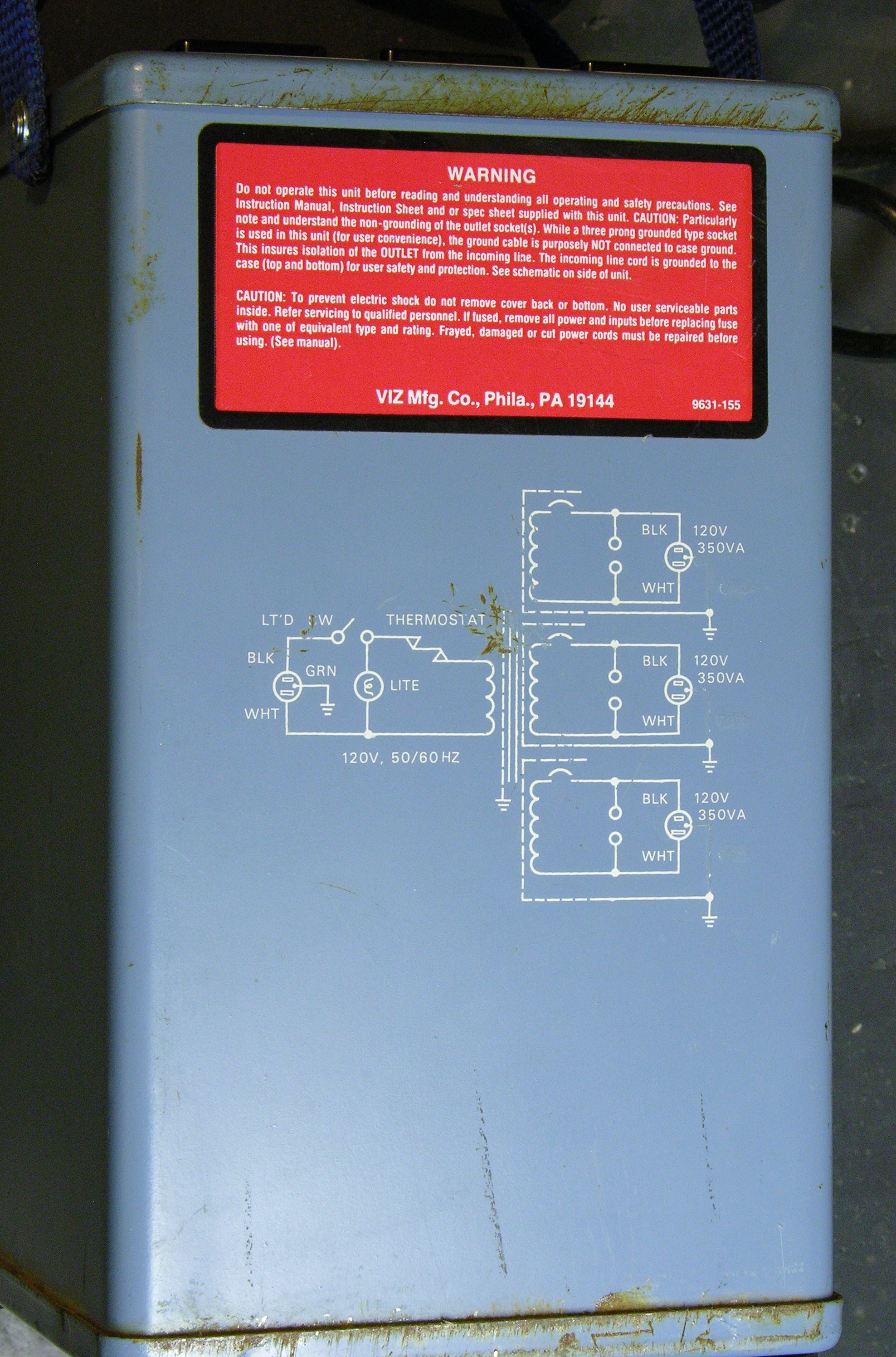
(And by the way, I think it’s really darn cool that the schematic is printed on the side. Yes, operation of this device is obvious. No, I don’t have to understand its construction in order to use it. But seeing the schematic instantly reassured me that I understood what I thought I was understanding. Yay, VIZ Mfg. Co.!)
So the transformer has 5-15R receptacles to accept grounded plugs, even though the ground lead isn’t promised to be connected; and it’s ludicrous to think I won’t use it for isolating equipment that should be grounded during normal use.

Thus it seems odd to me that the grounding hole on each receptacle was originally filled with plastic. A former owner had already cleaned (most of) the plastic out of the rightmost recep’s grounding hole, and last night I finished the other two with a 3/16″ bit.
Riveting the Handles Back On
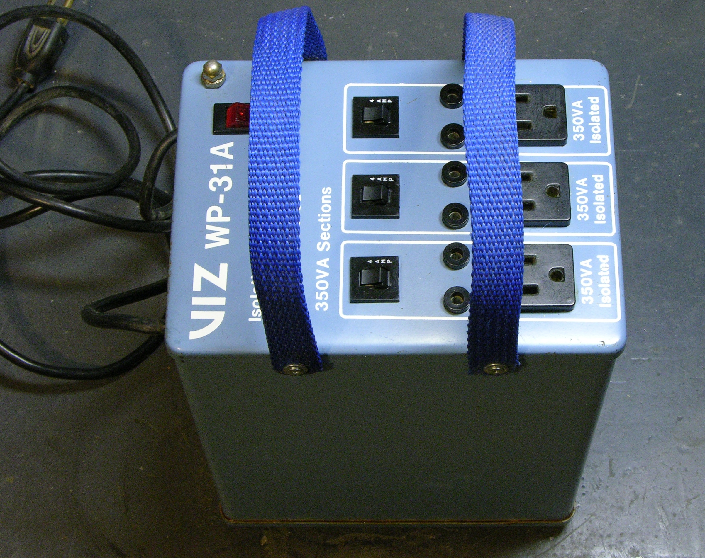
The transformer came with these nylon handles attached — which is a good thing, because it’s unpleasantly heavy to pick up off a tabletop or floor without them. Tilt it to one side, stick hand underneath, think about being moored to the spot for eternity if you get too tired to lift it, etc. (Hm, maybe I should rebrand this the Prometheus.)
The same rivets that hold the lid on also hold the handles on, and the last part of buttoning everything up was reattaching them. They had originally been able to swivel; so you carry the transformer to the site, swivel the handles down out of the way, and have unobstructed access to the face.
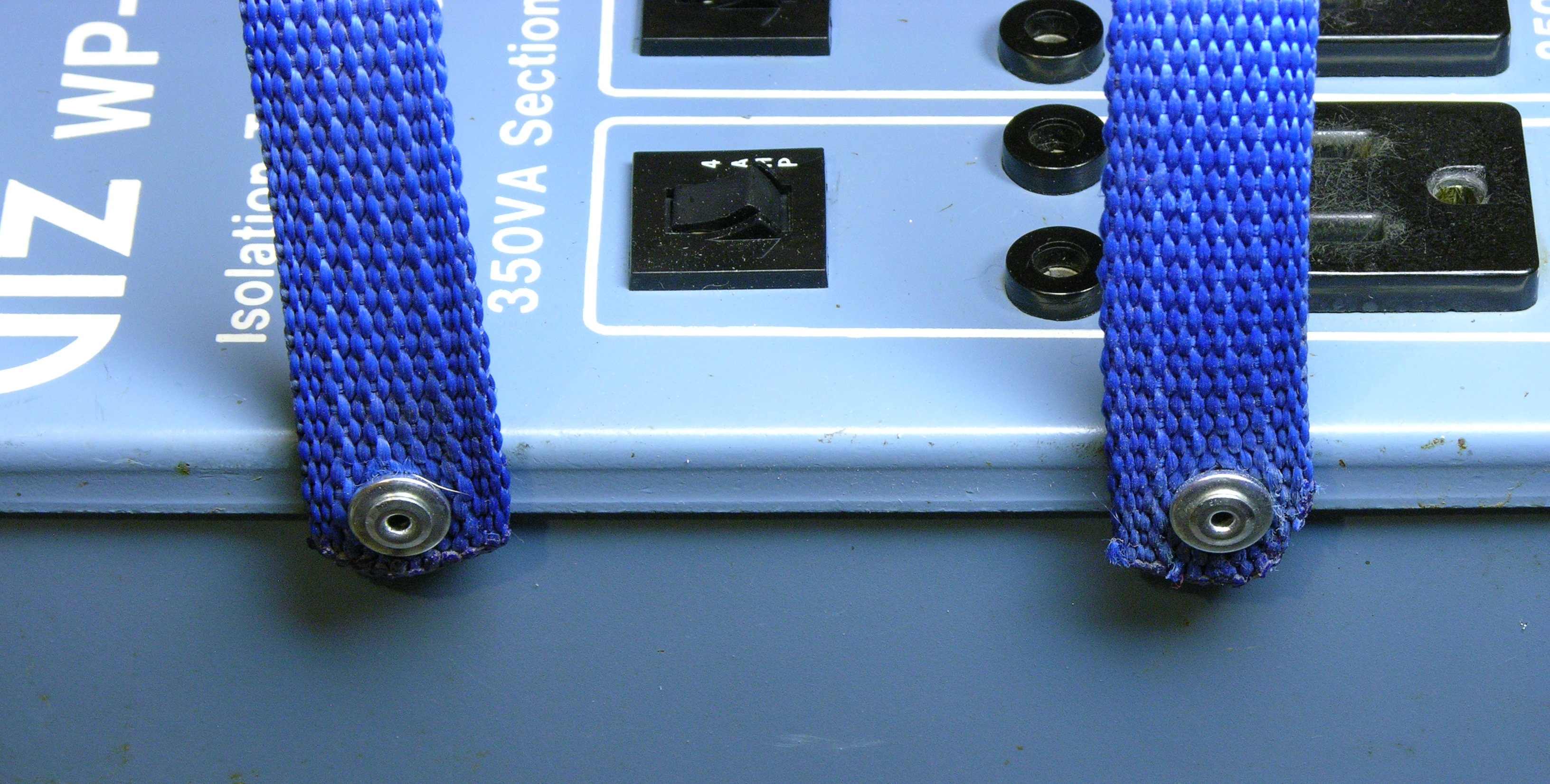
Two of the nylon ends still had brass bushings in them to keep the rivets from pinching the nylon too tightly for swiveling action; but even so, my first attempt to reattach resulted in a very non-swiveling handle.
I ended up turning the bushings backwards, and making two replacement bushings by filing the caps off of leatherworking rivets until I was left with just the stovepipe sections. With the bushings and homemade bushings installed backwards, the wide flanged ends seated against the lid’s edge (instead of being forced into the rivet holes by the action of the pop-rivet gun) and kept the rivet heads spaced far enough from the body to avoid pinching the fabric.
The handles swivel now.
Post-Assembly Test
All receps work. With a supply voltage of 119.5V, the receps measure 124.4V, 124.5V, and 123.9V with no load. The handles facilitate easy carrying, and swivel out of the way for easy use. The case is nicely cleaned and looks better than it has for years. I’d say that’s the end of a pretty nice restoration.
Except I realize I forgot to replace the superfluous rivets in the bottom of the case. Ah, well, always something more to do.