Last weekend, I had repaired a Soundcraft mixer switching power supply, but still had switching noise spikes from the transformer primary showing up on the circuit’s ground, and asked whether anyone could suggest how to reduce them or whether they were an artifact of the way I was using the oscilloscope.
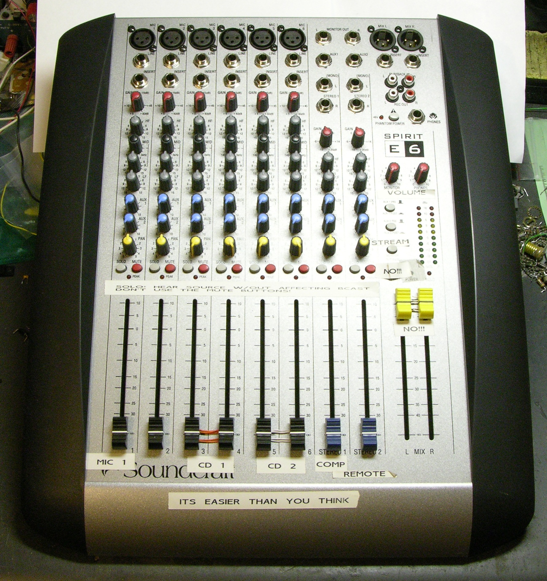
Many thanks to everyone who wrote in with ideas! Because of your suggestions, the mixer is now fixed (enough), back together, and ready to go back to the radio lab.
Here were the ideas and their results:
Noise Is Probably Okay; Tweak Snubber Values
MikeS wrote in to say that the noise is not unusual in a switcher and probably not important. I heard that from a number of people, and it’s reassuring to get the same answer from so many places.
MikeS also corrected my misinterpretation of the function of capacitor C20 on the transformer primary. It’s a snubber to help filter these very spikes, and I should have recognized that. Changing C20 and R15′s values might help reduce the spikes — although I increased C20′s capacitance and decreased R15′s resistance with no discernable difference in the noise, so that didn’t seem to be the ultimate solution.
FET Gate
MikeS suggested that increasing the value of R2 on the FET gate would cause it to turn on more slowly, decreasing the ringing at the cost of decreasing switching efficiency and increasing FET heat dissipation.
In an offline conversation, Tom McGuire suggested the same thing, as well as that a ferrite bead on the FET’s drain lead could help suppress the spikes.
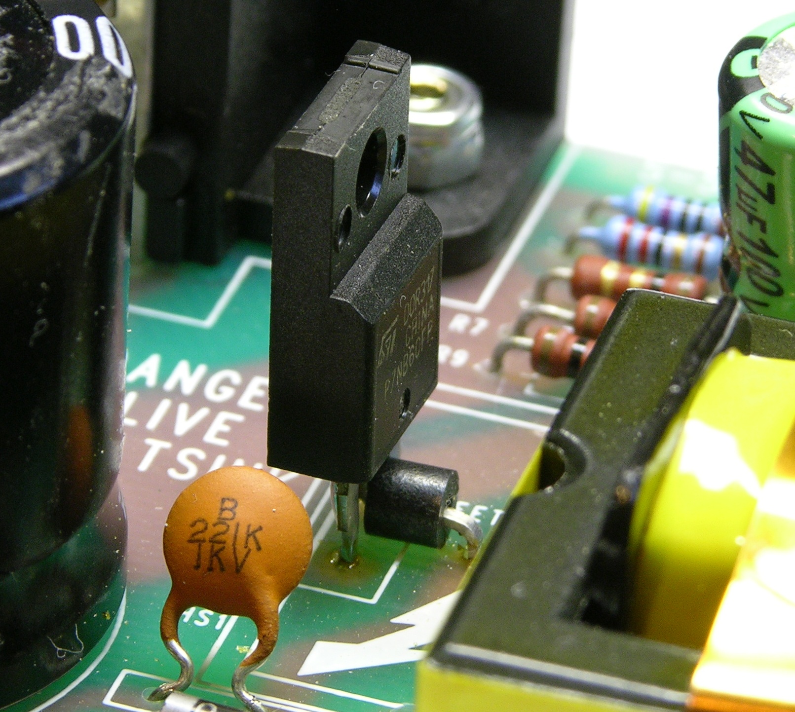
This turned out to be the most noticeable difference I was able to accomplish to the behavior of the actual circuit. I took a bead off of a FET salvaged from another switching power supply and installed it on the drain lead of this FET, and the ground ringing dropped in amplitude from .5V peak-to-peak to about .2V p-p. That was a pretty impressive achievement!
I hadn’t yet got to changing R2 on the FET gate (to make it turn on more slowly) and the suggestions were still coming in, so I didn’t try that right away. I’ll return to that point momentarily.
Circuit Inductance and Path Lengths
Bill gave me a link to an incredibly easy to read, useful set of lecture notes from UC Boulder’s R.W. Erickson on “EMI and Layout Fundamentals for Switched-Mode Circuits.” If you have any interest in the topic, this is well worth a quick read!
Per suggestions in the notes, I tried adding a bypass capacitor from the transformer primary’s positive side to the FET’s source using physically as short a path as possible. Perhaps the method doesn’t apply exactly to this situation; perhaps I wasn’t able to get the path as short as it should be since I couldn’t change the board layout; or perhaps the phantom nature of my spike (next) kept it from being suppressed by this method. In any case, this didn’t make any change to the signal I was seeing on the scope.
It was great reading, though; and I’ll be referring to it for some of my own future board layouts.
Scope Probe
Several people suggested through the comments and in offline conversations that what I was seeing on the scope didn’t really reflect what was happening in the circuit. Bill also suggested shorting the scope’s tip and ground lead together at the probe and repeating the test.
I clipped the ground wire to the probe’s tip and moved it around near and in the circuit. Throughout most of the PCB, as I approached closer than 3/4″ to the board, the spikes returned on the scope, increasing to full amplitude as I got all the way up to touching almost any pin I tried. This demonstration screamed “antenna,” and also “what you’re seeing on the scope may not represent actual voltage changes in the part of the circuit you think you’re measuring.”
Mark pointed me to an article on scope ground connections and ringing! (Scroll about halfway down to 10-Jul-2007.) The article shows a 20MHz clock signal causing “ground bounce” through the inductance in the scope probe’s 6″ ground lead, and shows using a super-short grounding clip instead to reduce the ground bounce.
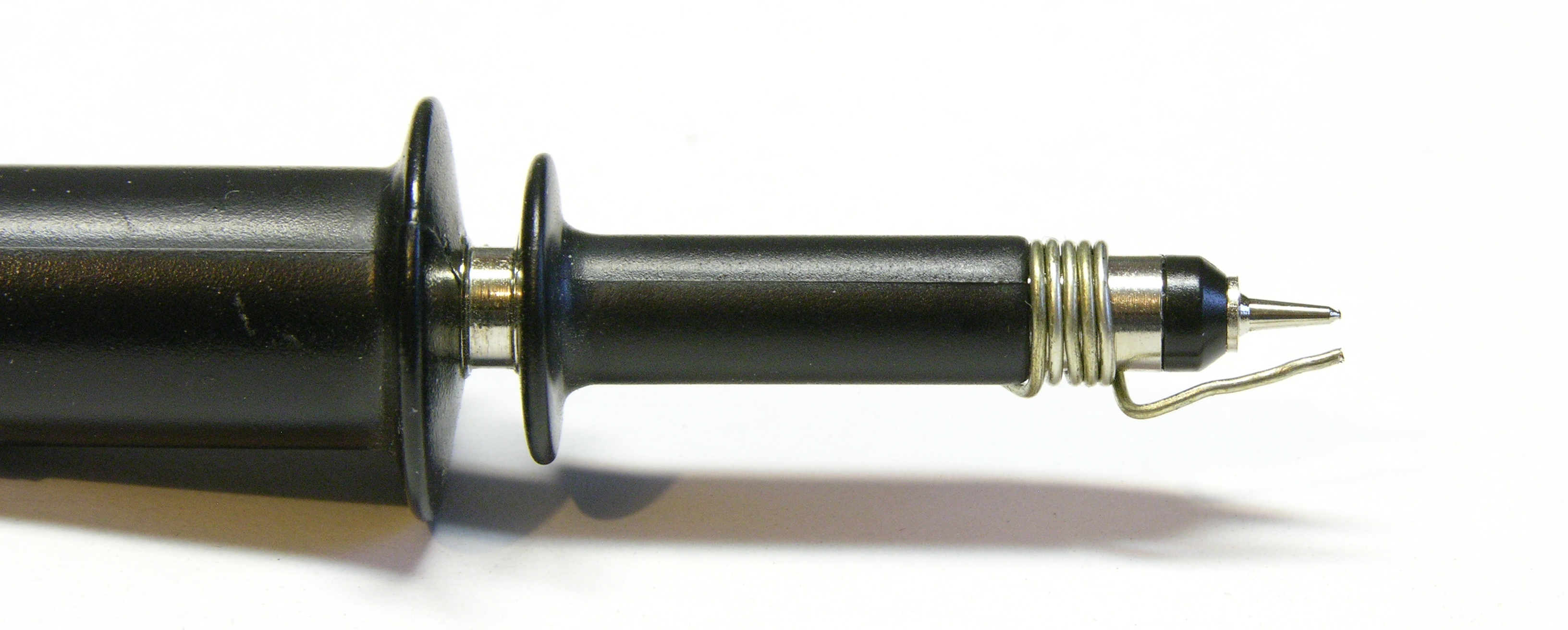
Hoo-RAH! Using a homemade test clip (the high-fallutin’ term for some wire wrapped around the probe’s ground shell), the displayed spikes dropped an order of magnitude from the post-ferrite-bead .2V p-p to only 20mV (.02V) p-p!
This strongly suggests to me the accuracy of the article’s claim that the ground lead’s inductance was causing the display of spikes. AND because the displayed ringing had now been reduced by over an order of magnitude, I decided not to bother experimenting with the FET’s gate resistor — it just didn’t feel worth it any more.
The mixer was now “fixed” (in both reality and scope displayality) but one more point had come up in the comments:
Overheating
MikeS had suggested that capacitors C1 and C8 may have had too high an equivalent series resistance (ESR) and cooked themselves.
Dave was troubled enough about the overheated board to do some calculations, and pointed out that R3-4 will be dissipating almost half a watt each (the voltage across them is probably slightly higher than what he used in his calculation), and that’s pushing what they’re rated for.
I powered up the circuit for a few minutes and then used my IR thermometer to take readings of the different components in the scorched area. I recognize that I’m trying to hit pretty small targets and it’s hard to be sure I’m measuring what I think I am, but here’s what I got:
| Component | Temperature |
|---|---|
| IC1 | 120°F |
| R3-4 | 90°F |
| R11 | 118°F |
| board under R11 | 120°F (hotter than R11) |
| R13 | 130°F |
| R16 | 142°F |
| C1, C8 | 85°F |
| D2 | 135°F |
This looks to me like R13, the bootstrap resistor, really does get pretty warm; and like R16, the little guy in the primary side’s main VCC voltage divider, also gets quite warm. I can’t completely explain why that should be and I’m also not completely certain that I’m measuring the right things …
But the fact that C1 and C8, up on “stilts,” are only getting up to 85°F, and being further from the board should help isolate them from heat transfer through the board, and the replacements are rated for 105°C, I don’t think the capacitors are going to fail again (at least not nearly as quickly). And the hot resistors aren’t what failed the first time, so I’m hoping they won’t fail any time soon. Thus I’m feeling pretty good about leaving the resistors be and calling this good enough, which is what I’ve done.
The Snubber wikipedia link is broken. Great article again, thanks for summarizing everything. The EMI and scope probe links were worth their weight in gold!
Kai, thanks for pointing out the broken link. I had been careless pasting it into the form, and it’s fixed now.
Regarding the links — yeah, they’re fantastic! And I doubt I could have found them even if I’d tried searching for them. It’s really great having people who know where the good stuff is and interested enough and willing to help others out.
Keith – I relly should have read all related articles before posting on the original repair article…oops. Another good article here, by the way – thanks.
Looking at Your very nice schematic of the powersupply, I notise, that You write 230 Volt ac at the mains inlet, but You write 170 Volt dc on the large 100 uF/400 V C18! Could one of Your diodes in the bridge be open circuit? I am right now sitting with a defect PSU. All pins on the ic is active, exept the drive for the FET. Luckily I can buy a new PSU, but these PSU’s tends to go faulty. – thought of making an oldfashioned linear PSU, as Rod Elliot makes them. the high voltage for the phantom voltage, could be made by voltage doubling of the 18-0-18 voltage from the transformer. Great blog.
The 230 VAC at the mains input is the rating printed on the capacitor, not a measurement I took. Sorry for the confusing notation!