All along, I’ve been having trouble with the filament feed on my CupCake extruder. Regardless of how closely I position the idler wheel to the drive pulley, the slightest blockage at the extrusion nozzle (even sometimes removing the text extrusion with needlenose if I get too close) causes the timing pulley to ream out a pulley-sized divot from the soft ABS.
There’s then no way for the extruder to move the filament — forward or backward — until I get pliers and apply considerable force to the filament at the intake to move the divot past the pulley.
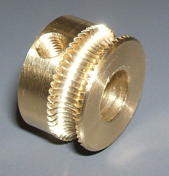
In April last year, nophead tested different drive methods and found the threaded pulley (as above) to provide the strongest grip on ABS. (Search in page for “The final test was a threaded pulley” to see his technique and results.)
nophead isn’t the first to use this technique to manufacture a threaded pulley and I’m not the first to copy his notion of using it on a RepRap, but I’ve lost my links to many of those who have done it before.
At any rate, I installed one on my CupCake this weekend and the results are considerably beyond my expectations. Here’s the story.
Machining the Pulley(s)
I got in touch with my friend Mike Smith from Pittsburg (as opposed to my father-in-law Mike Smith from Hugoton) who works in the university’s technology center where he has access to all kinds of machines, has a metal lathe at home, and for fun does things like hand-rewind the coils on CD-ROM drive pancake motors to make new motors for small electric RC aircraft. I described what I was after and asked whether it was something he’d be willing to take on.
My project piqued his interest — he sounded amenable and asked for more information about dimensions. I offered repeatedly to take apart my machine and confirm the pulley and motor measurements, but he was satisfied with the dimensions I found on the existing timing pulley’s datasheet. Within a matter of days Mike had machined me two beautiful threaded pulleys and sent me the pulleys and the following information about their manufacture:
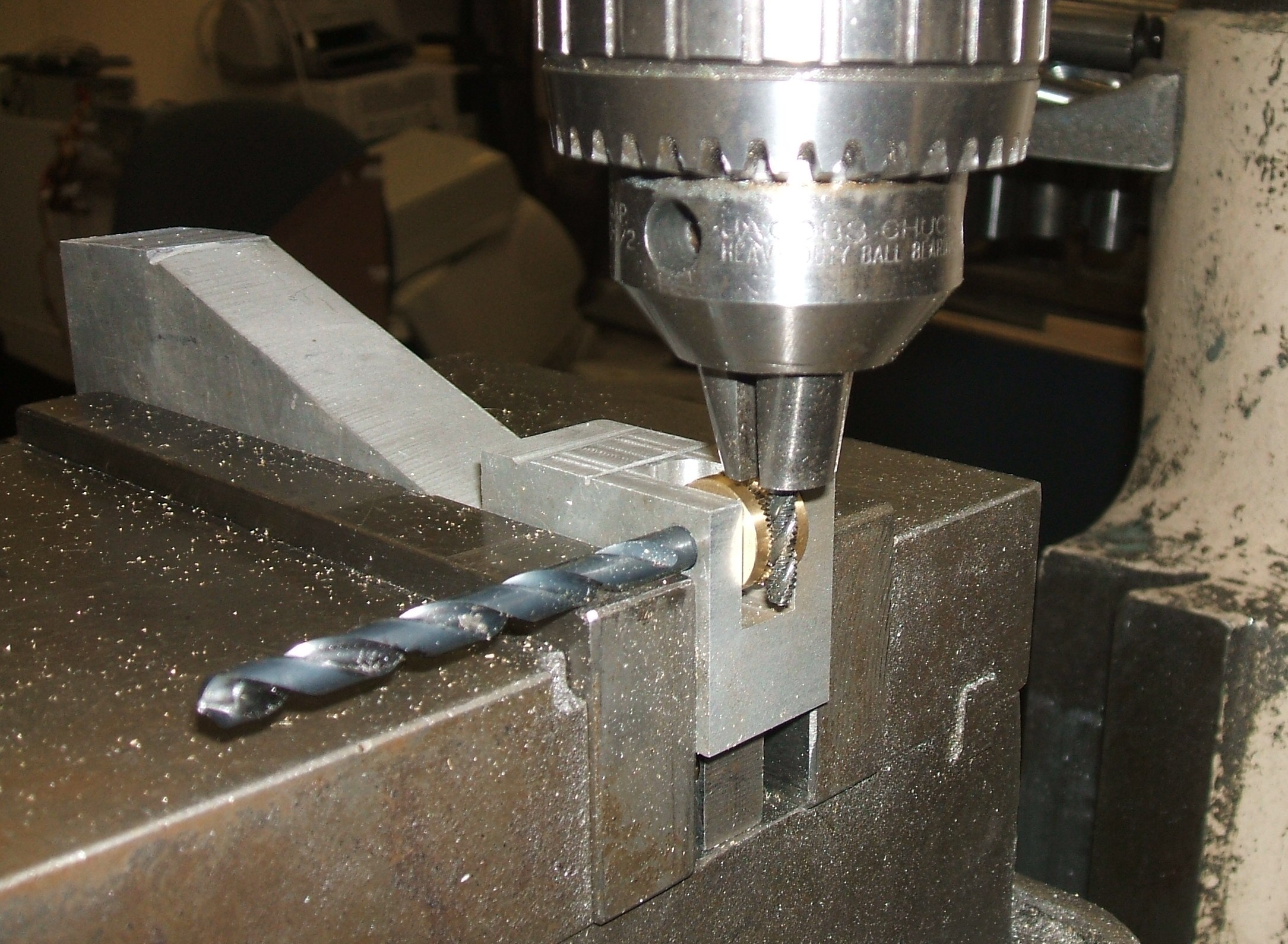
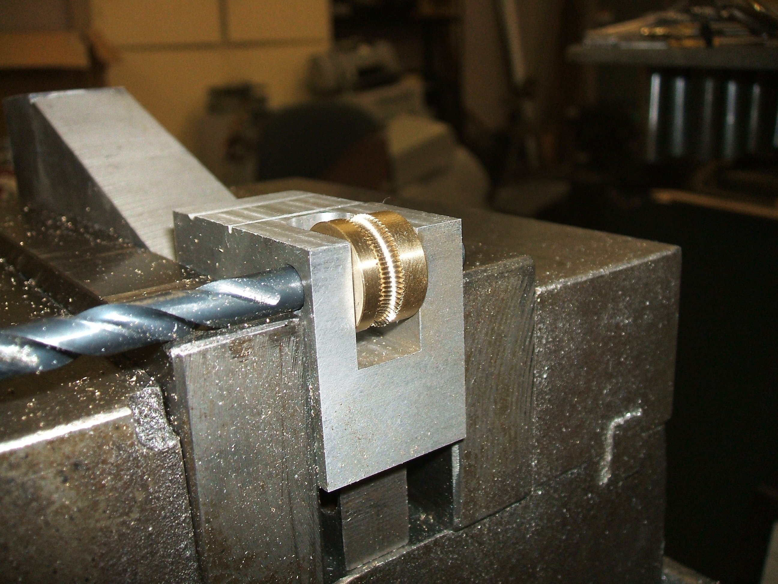
The tapping is the hard (tedious) part since I have to stand there and advance the table on the mill .001 inch every turn or two of the pulley which is about every 15 seconds while blowing the cuttings away with the air hose to keep the tap clean. I used tapping oil the first couple of attempts but that made the cuttings stick to the tap and build up and I think that made it grab and break the tap.
Every .005 I let the pulley turn about 5 turns and watch for the cuttings (like brass dust) to subside as there is no good way to tell how much side load I’m putting on the tap and they don’t bend much before they snap. Imagine an 1/8 drill bit in your drill press and trying to cut a notch into the side of a piece of metal by pushing it against the side of the spinning drill bit but you can’t feel how hard you’re pushing.
I used the tap to cut the entire groove. Thought about getting it close in the lathe but decided it may cause problems trying to align the tap with the groove. I was surprised that the threads appear to line up perfectly as the pulley completes one revolution, I’d expect them to be a little out of sync if the diameter wasn’t just right. I guess since the tap is what rotates the pulley it rotates it at the proper speed regardless of the diameter.
Replacing the Timing Pulley
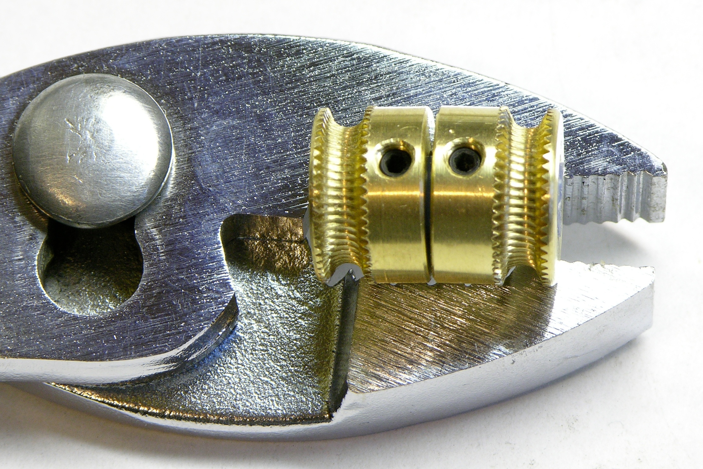
Mike sent me the pulleys fitted onto a piece of rubber hose (knowing Mike, I’m guessing RC aircraft fuel line). They look so small!, but I know those are the dimensions we talked about.
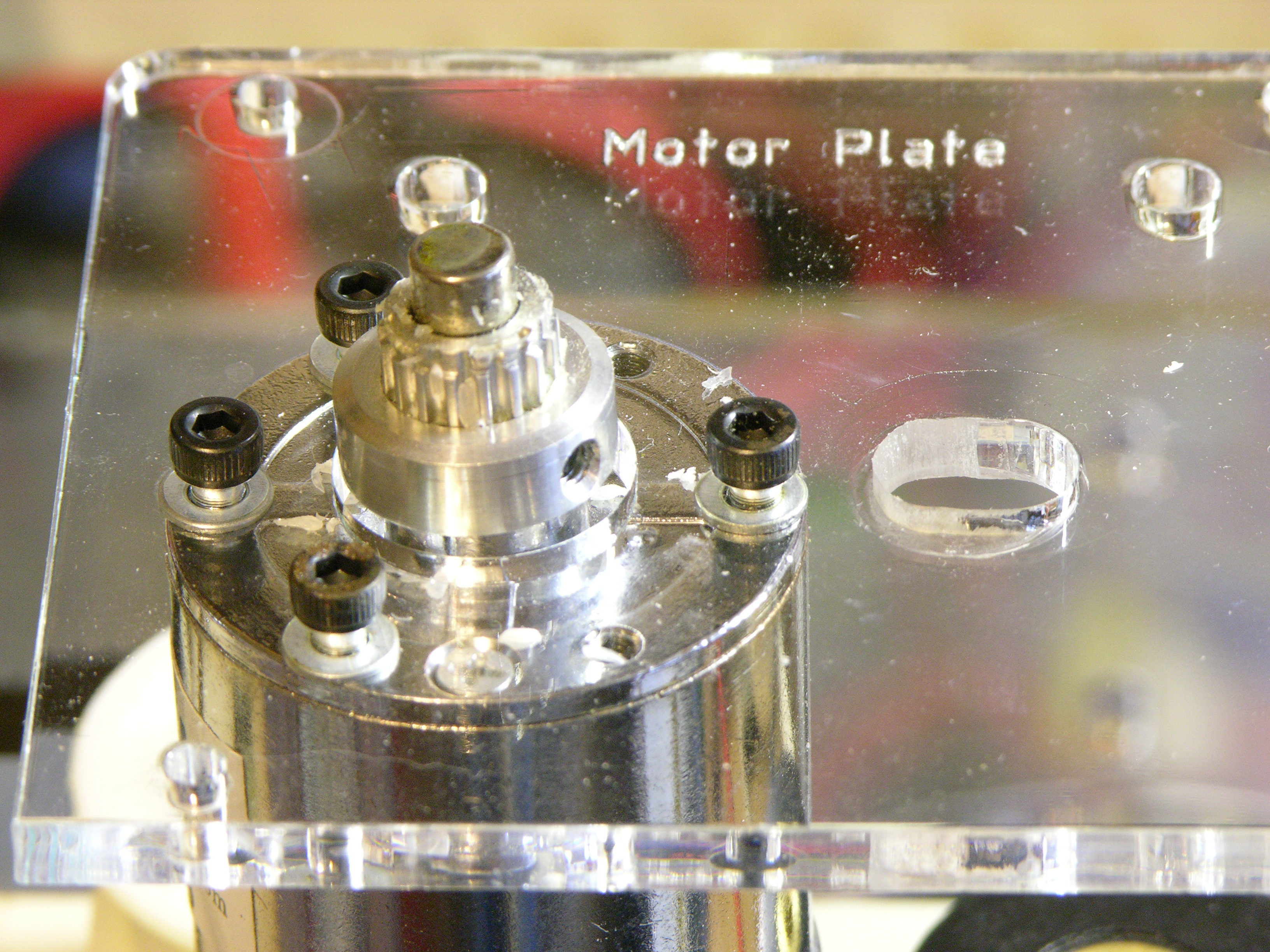
I removed the timing pulley (outer flange previously broken off) from my Plastruder.
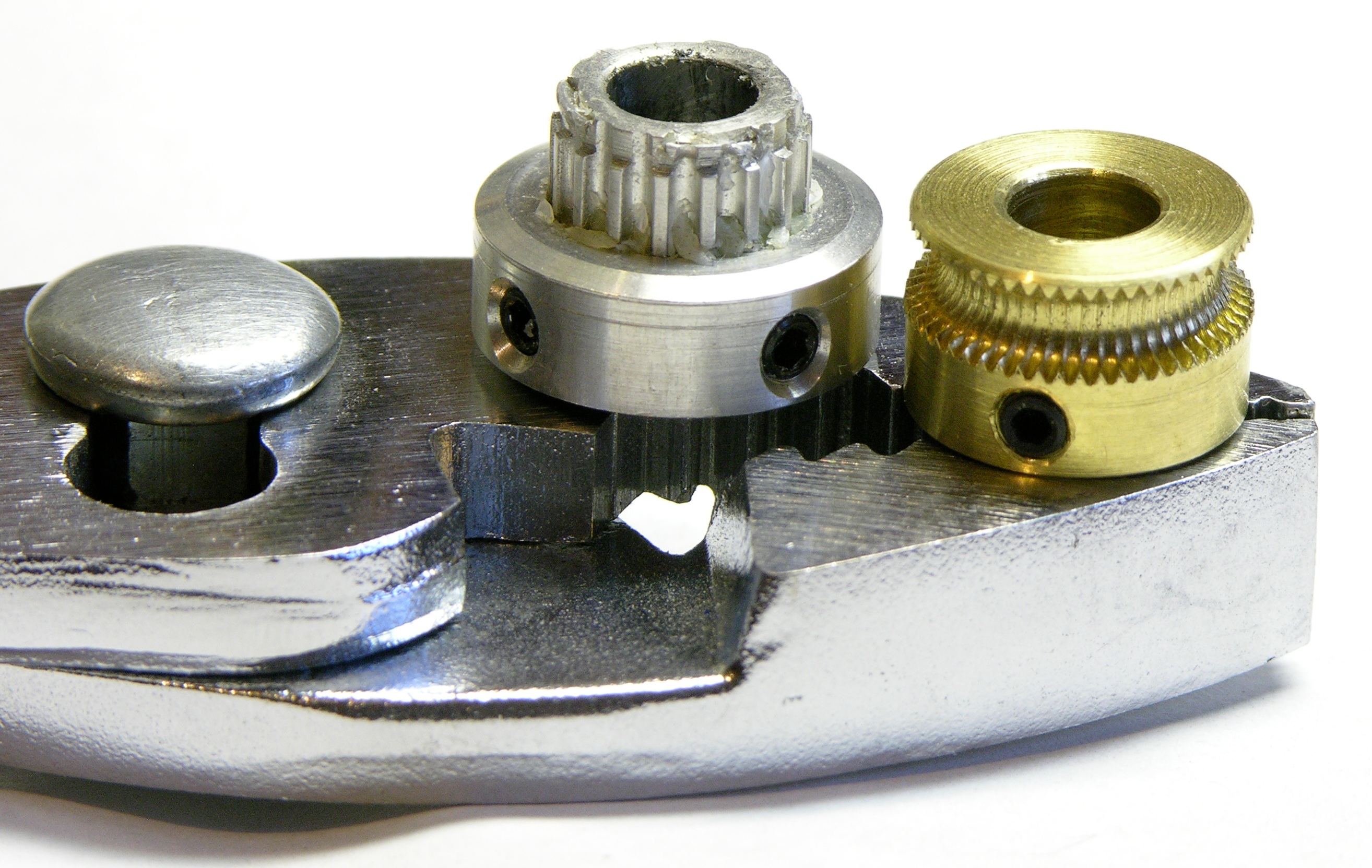
Sanity check: Yeah, they’re in the same ballpark.
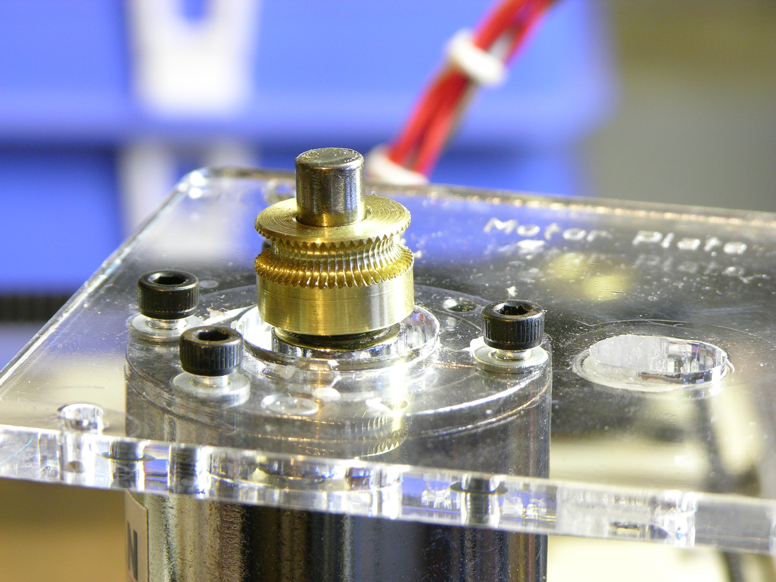
The new pulley didn’t quite fit onto the motor shaft, which I now measured at an actual .235″ = 5.969mm. I filed the inside of the new pulley just a smidge and it fit perfectly.
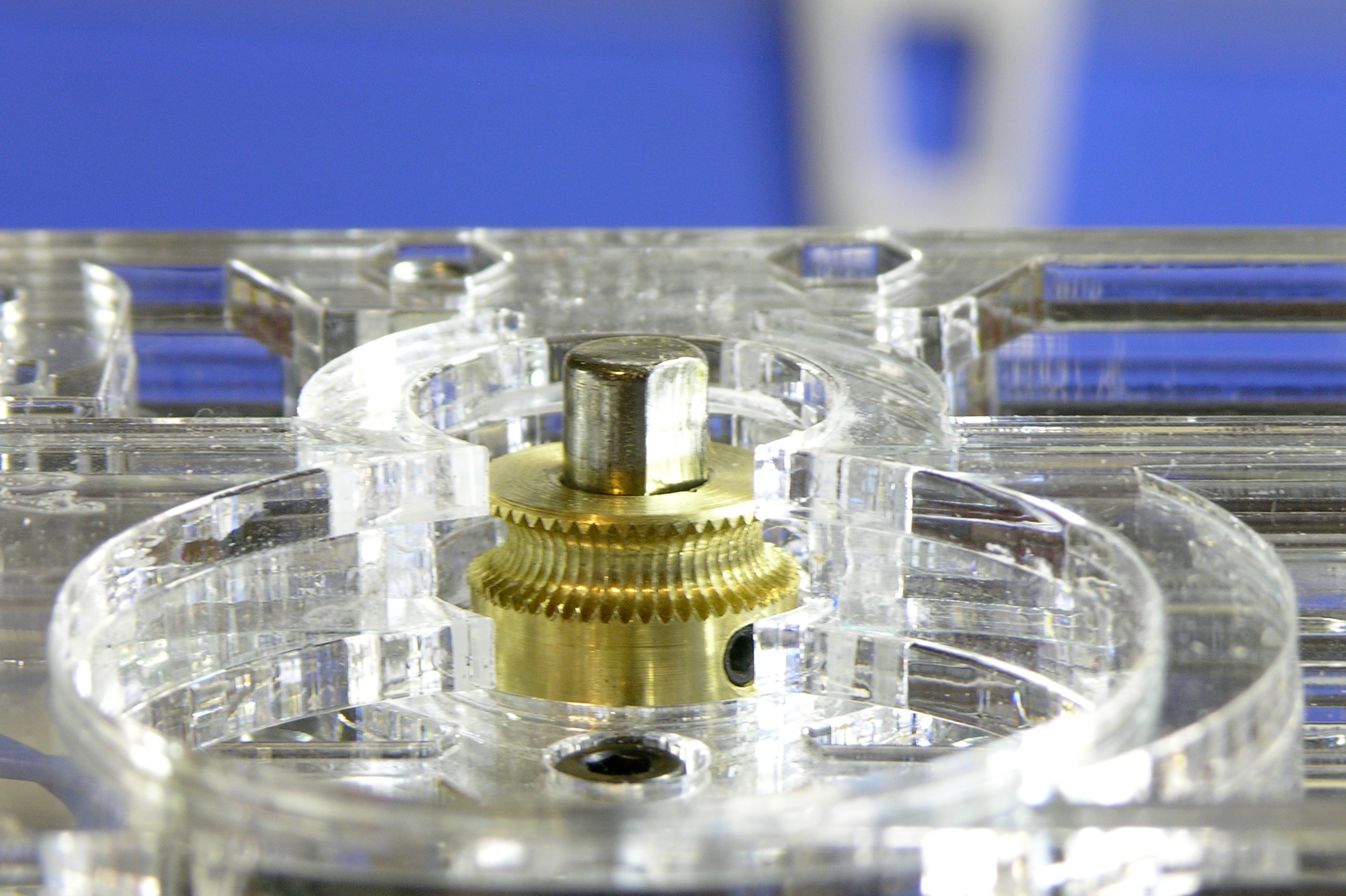
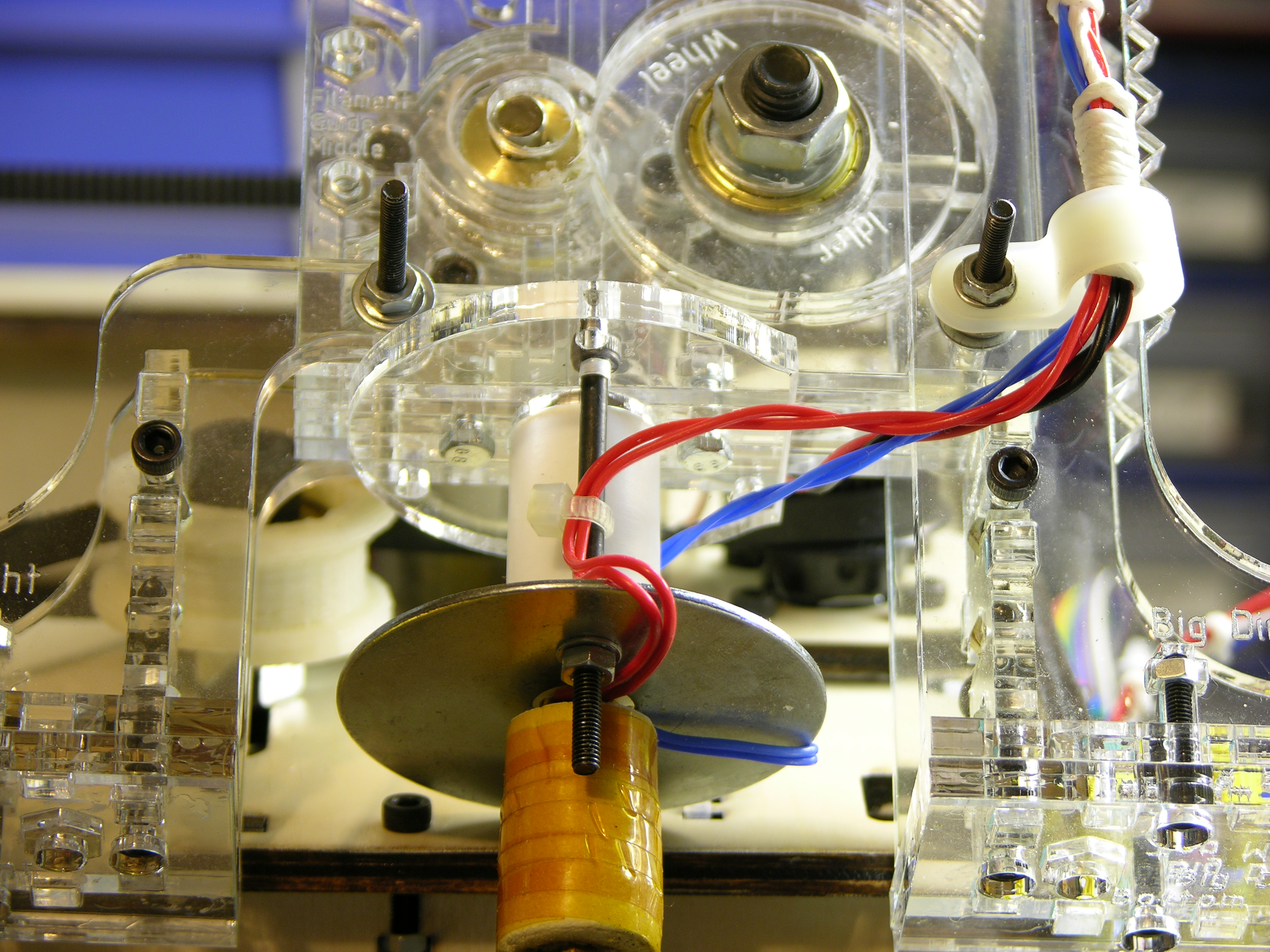
I took some care to position the pulley on the shaft with its groove aligned with the Plastruder’s filament guide channel. The timing pulley, having a wide and flat gripping surface, didn’t have to be aligned quite as carefully with the filament (and mine probably wasn’t).
Grippy!
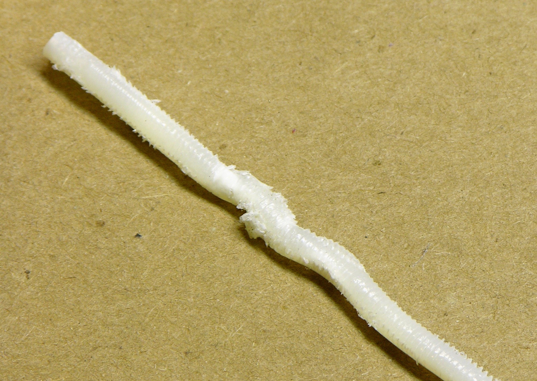
Contrary to the old adage, you can push a rope if it’s slippery and you stuff it into a narrow channel. The new pulley has such good grip that it was able to push the filament into a kink within the body of the Plastruder when the extruder nozzle wasn’t quite warmed up enough yet.
As a matter of fact,
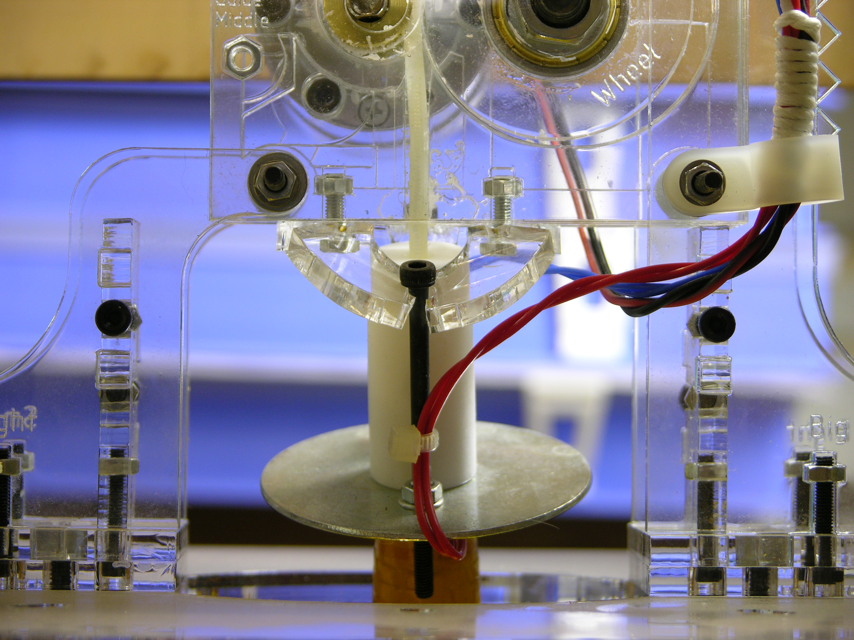
Does your extruder have enough grip on the filament to push the nozzle right off your machine? I think not!
Mental note: Just because the thermistor thinks it’s 225°C doesn’t mean it’s time to turn on the feed motor. I’ll give it a little more time to warm up in the future.
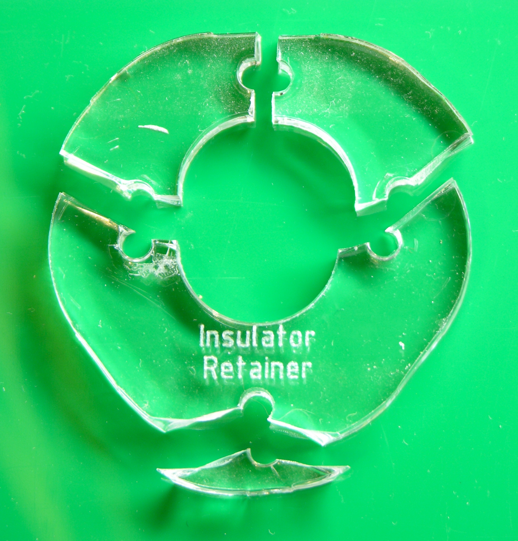
The retainer plate that mounts the insulator and heated section to the feed section broke, well, everywhere.
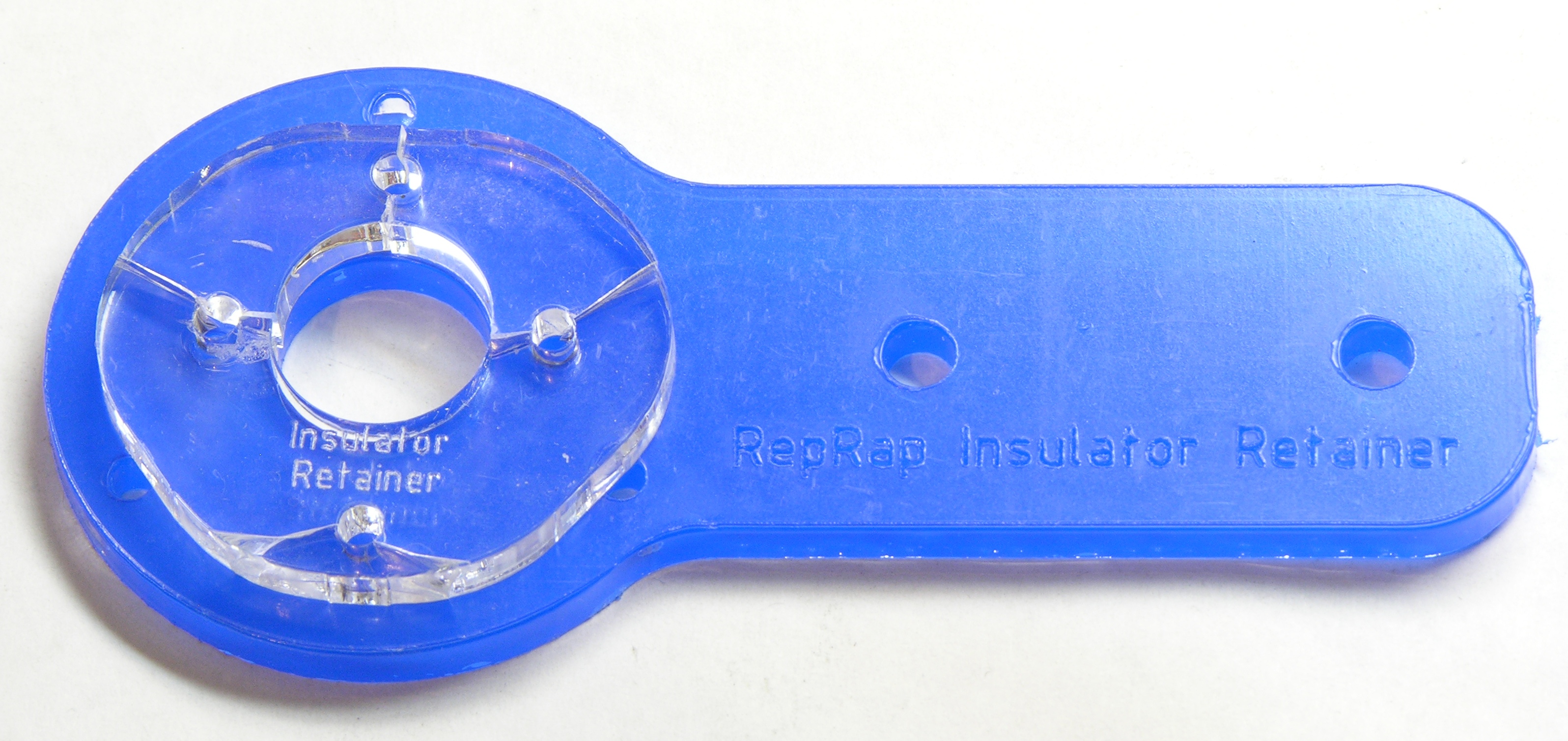
Fortunately I had a spare RepRap retainer plate from my Plastruder kit. It had the same mounting holes for the feed side; I just had to mark and drill new holes for the heater bolts, then cut off the excess (mounting tab???). The part I care about is even a little wider than the original plate for the CupCake, so it should be a little stronger too.
Remounted on the Plastruder and ready to go.
I’m thinking I need to get a plate machined from aluminum so I have it ready when I break this one. The holes for the long heater bolts could be tapped so they thread up from below and don’t require nuts, too.
Printing in Plaid!
I’ve been concerned from day one about the feed design — having the feed wheel press the filament against a rigid idler wheel. That would be fine if the material being fed had compressive elasticity (I don’t know the proper ME term — feel free to educate me) and would spring back when squished.
But the ABS largely has compressive plasticity, meaning you squish it and it stays squished. As the feed pulley presses the ABS against the rigid idler, the filament deforms and the grip decreases; whereas you would really prefer that it the pulley deform elastically and push back harder to increase grip.
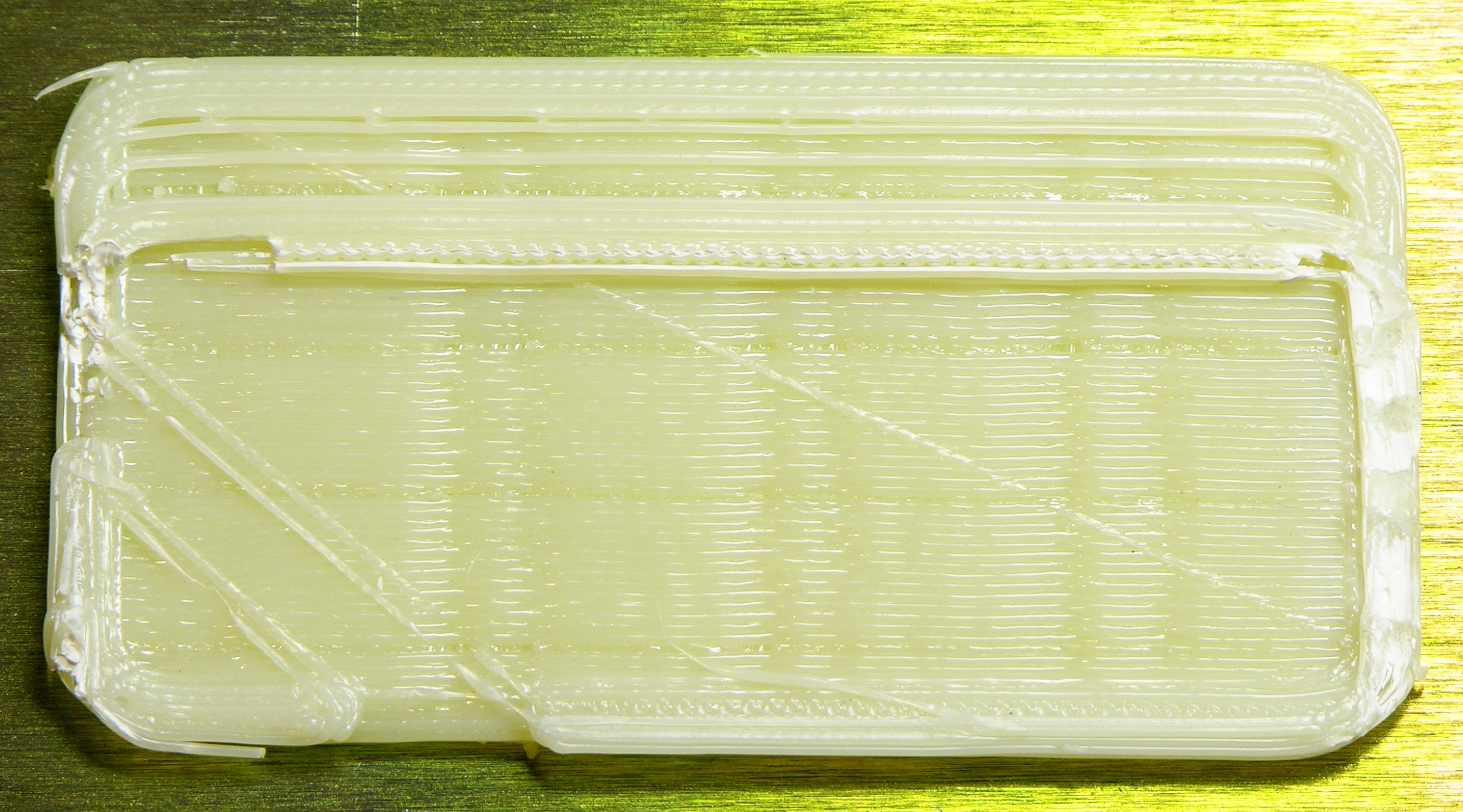
Although the threaded pulley has a stronger grip than the timing pulley on properly “idlered” ABS filament due to sharper teeth and a larger (curved) contact area, its teeth are shallower than those of the original timing pulley. The threaded pulley squeezing plastic filament against a rigid roller thus reveals the irregularities in the acrylic idler wheel.
The regular vertical valleys above, and the slightly less visible horizontal valleys, are where the same slightly low spots on the idler wheel rotated back into position, the pulley had a little less grip, the feedrate slowed, and less filament was extruded. If it happened once, I’d chalk it up to chance; but at regular intervals like this, it’s pretty clear that it correlates to the idler wheel. And I can feel the roughness all around the idler wheel — it looks and feels like melting from the laser cutter.
(The lost steps on the Y axis and the upper wall that moved out of position, by the way, are due to now severe deformation of the acrylic underneath my heated build platform. I’ll deal with that next.)
While trying to get the idler wheel close enough to keep the filament consistently pressed against the threaded pulley, apparently I got it too close, as during the next run the plexiglass idler broke radially and lost its grip on its bearing and its interest in turning.
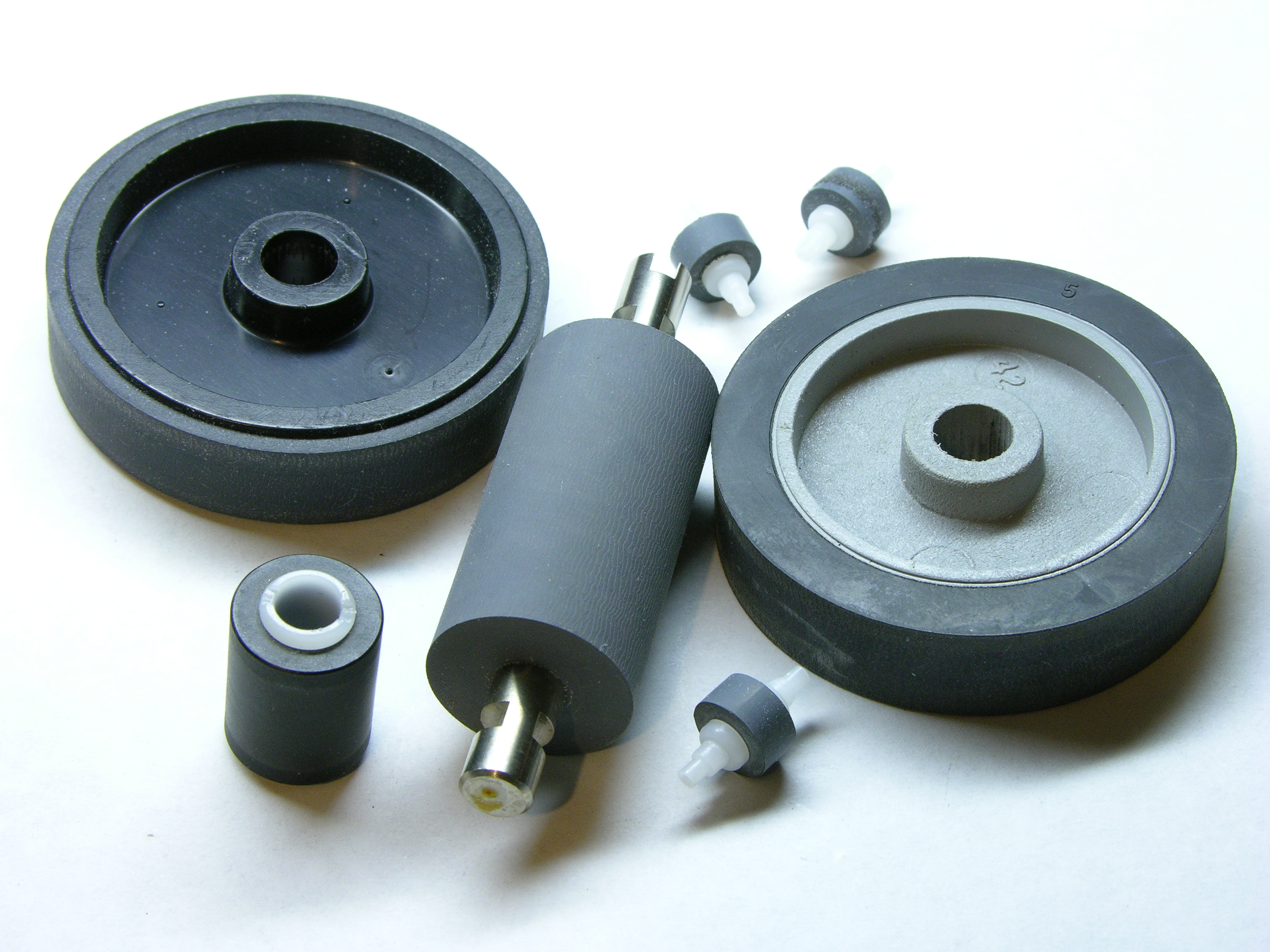
As hinted above in my discussion of elasticity, I’ve been thinking about replacing the idler wheel with a hard rubber pinch roller. You’d think with all the things I’ve salvaged, I’d have one about 1.6″ diameter and .25″ thick in my parts bin, but alas, I do not. I’m asking a couple of friends about their parts bins, and meanwhile I’ve found about the right thing at McMaster-Carr for $16.
Whatever I do will probably require designing a new bearing, as my new wheel is unlikely to have a bore matching the skate bearing in the current design.
Depending on how much rework is required, I may look into mounting the new bearing eccentrically in a cylinder so one screwdriver on the back cams the roller position toward and away from the filament and another screwdriver on the front locks the assembly into position. It’d make it easier to adjust the roller pressure than the current slot design — obviously at the cost of increased complexity.
Fantastic pictures Keith. What sort of camera do you use?
Nophead, your compliment is especially delightful because it’s not the camera, it’s the technique! (Old photographer’s boast.)
The camera is a hand-me-down Nikon Coolpix 8700 (ca 2004). It’s so old that all my indoor pictures (even under spot lighting) have exposure times of 1/4 second and up. That means I use a tripod on every shot, and I bracket exposures extensively because I can’t trust the meter. I calibrate white balance to a sheet of paper before every photo session and I shoot and examine a test picture before every shot to see whether autofocus is acceptable or whether I need to manually focus. After uploading, I examine all the shots on the computer, select the one with best brightness/contrast, and crop better than I’ve learned to do in the viewfinder.
Yes, I need a DSLR!
Seriously, I don’t know that my photos look any different than yours; so while the praise is appreciated, I don’t know that it’s necessary.
I’ve broken several acrylic insulator retainers and have since switched to printed insulator retainers and none of these ABS retainers have ever broken on me. See: http://www.thingiverse.com/thing:1004
I also screw the barrel directly into the block for more strength like this: http://www.flickr.com/photos/tbuser/4428088597/
As for the idler wheel, I got a pretty nice one made out of aluminum that should never break, see: http://tonybuser.com/indestructible-aluminum-idler-wheel
Would it be feasible to add sensing to the extruder motor to limit the force applied to the filament? Besides “not breaking your extruder”, I would think it might also be useful for being able to detect the “heater not actually hot enough” problem, or noticing if your extruder just isn’t working as smoothly as it used to/ought to.
Kevin, motor current sensing should certainly be possible — although perhaps tricky since the controller already PWMs the motor for speed control, so it would have to be highly integrated.
Since the motor is considerably geared down, I’m not really sure how much current difference one would see — it didn’t really seem to be straining any harder when it was tearing my machine apart.
Actually, in our build of a Darwin, we retrofitted this extruder head. We managed to push it apart because the alignment between the threaded copper heater tube and nylon collar was bad. The drive mechanism pushed the copper tube straight out of the insulating collar.
It is possible, even without a new super-grippy.