The MAX16823 that my LED driver is built around uses current-sense resistors to set the LED strings current to .203V / R.
So for the maximum 100mA, R = 2.03Ω; for 20mA, R = 10.15Ω.
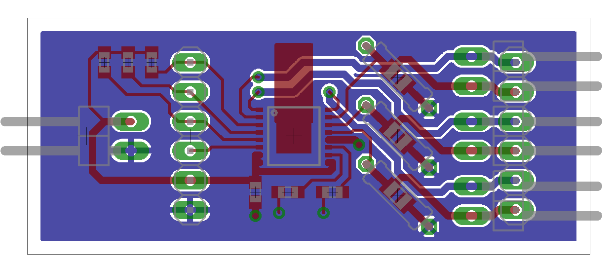
I’ve laid out the board to accommodate both SMT and through-hole sense resistors. I’d like to offer boards preassembled for at least 100mA and 20mA and boards without sense resistors so you can provide your own resistors for custom currents.
Should I offer other preconfigured currents besides 100mA and 20mA? Do I need to bother with 15mA?
Let me know in the comments what currents you’d like to have. Just because you ask for something doesn’t mean I’ll provide it; but if enough ask for the same thing, I very well might.
One option would be to install surface mount resistors for 20 (or even 10) mA. For higher currents, the end-user could install a through-hole resistor in parallel with the installed surface mount resistor.
This makes it usable out-of-the-box while allowing the end-user to make adjustments without much trouble.
On another matter, I just went back and saw that you’ve been using the same small copper tab sticking out underneath the MAX16823 all along.
Since I presume you’re having boards with proper solder mask made for the production run, have you considered just doing a copper fill on the top layer? Would provide a bit more thermal headroom, but I suppose it might make soldering to the thermal pad a bit more challenging (were you planning on reflowing them, or hand-soldering the lot?)
And on a closing note: If you’re going with something pretty close to the design in this post, it’d be nice if you added a ~3 mm hole in the empty corner of the PCB, to make mounting easier.
I’ve been playing with RGB LEDs recently. I bought various samples I could find from DigiKey and a couple of Chinese distributors.
The most common current ratings I’m seeing are 30 and 50ma, with a few of the smaller ones at 20. Typically RG & B all have the same current, but blue and green typically have a 1 – 1.5 higher voltage drop, usally 2 & 3.5v or so.
+1 for 50mA!
Neat idea to allow both through hole and SMD resistors.
Perhaps a variation on Jon’s idea: just design traces that can be cut to provide the right resistance? I haven’t priced SMD resistors, but imagine they must be pretty cheap.
Expanding on Tom’s idea, you could install several resistors in parallel with solder jumpers to select one or several to use.
I have found however it’s harder to bridge a pair of pads with a solder jumper than you might think!
On the whole stacking-resistors thought: Since you’re using a double-layered board, you could at least throw some SMT pads in parallel with the sense resistors on the bottom of the PCB – this way, you can easily solder new SMT resistors on to modify the value. Perhaps just put two large pads with little separation – that way you can stick on anything from 0603s to 1206-size resistors.
And since soldering large-ish SMT resistors is pretty easy (and resistors are pretty cheap), perhaps you could offer complete 100ma and 20ma builds, and a 20ma build with included resistors to modify it to do 30/50 ma?
The parallel resistor required to turn 10.2 ohm into ~4.06 ohm (for 50ma) is 6.8 ohm, and 1206 versions cost 2.38 cents/piece @ Digikey (for 200+). For 30ma, it’s 20 ohm; same price.
So an additional BOM cost of 14 cents for the six additional resistors. Thru-hole versions are (surprisingly) marginally cheaper, and you can get six for 13 cents.
Trace-cutting is a pretty decent idea too – 0805 resistors are ~1.95 cents/piece. Does require a more finicky layout, though, and I doubt you’re very keen on double-sided assembly to avoid having to make the PCB bigger.
Thanks, everyone, for the suggestions so far!
Regarding what preconfigured currents to support, I like the 50mA suggestion — although as has been pointed out, that could be accomplished by adding parallel resistors. If I were going to configure a non-stock current, I’d rather supply my own resistors altogether than add resistance in parallel; but having the 20mA resistors already onboard certainly makes it easier to start using, and then add parallel resistance to get the current you want.
I’m not wild about adding jumpers or traces to cut. I’m already going to need to increase the board size slightly to make room for labels; I’d rather not have to increase it more for jumpers, extra resistors, extra traces, etc. Also having extra resistors and traces that could be cut to change the value would mean the board would come set for a higher current and you could lower it to get the right value for your LEDs, which doesn’t help you get off the ground quickly because it’s backwards from the way you’d be prototyping a new circuit.
JP, would you be disappointed to have to accomplish your 50mA by adding parallel through-hole resistors?
Regarding the board layout, besides the labeling mentioned above, I will absolutely get at least one mounting hole onto here (like Asm mentioned). The IC’s exposed pad is purportedly ground (I’ll confirm this) and if I widen the board (increase in the Y direction), I could have room to expand the thermal tab and put a mounting hole through it so you could bolt this onto a heatsink (or something that acts like one) using a short metal standoff.