Tinning the Board
The first step of assembly was tinning the board. I was going to be soldering a lot of jumpers to the top of the board, and the longer I had to hold the iron on each one, the further back the insulation would melt. Tinning the board (putting solder on all the pads) helps the solder flow almost instantly to each lead during component soldering.
I have a bag of Tinnit, which is a solution that’s supposed to tin the whole board for you. I’ve never opened it, though, because it has a relatively short shelf life once mixed with water, and I don’t make enough boards to be worth wasting a whole bag. I know, makes a lot of sense to buy a time-saving product and then never use it. Maybe when I’m ready to make the real clock boards, I’ll bust it out.
Anyway, I did it by hand with the soldering iron, running along each trace and depositing a little solder. It’s actually not bad work, and it drew my attention to every part of the board, causing me to spot a trace I forgot to draw back in and a trace that had come open while etching, which would have taken much more effort to find later in the process.

Jumper Wires
Next, I cut and installed jumper wires, in lieu of top-side traces on my single-sided board. For fun on the prototype, I color-coded them: blue for a connection between the driver and a blue LED, black for ground, and random other colors for different signal connections.
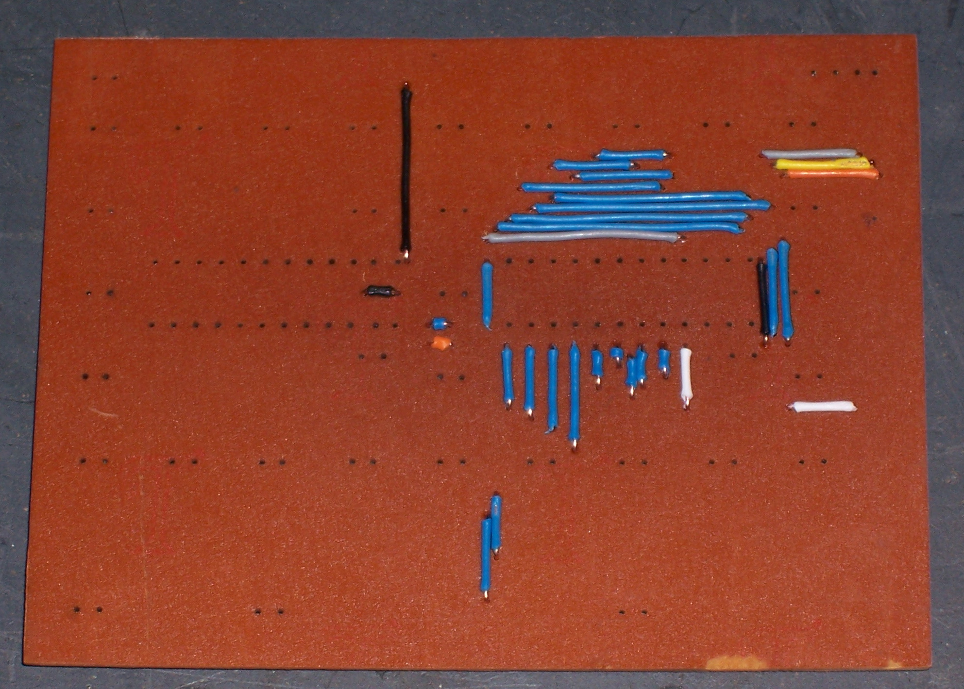
In retrospect, something about this process was a huge mistake. It took a long time to cut, strip, and bend all the wires to size; and doing them in different colors just made it worse. By the end of one prototype digit, I knew I never wanted to have to do that again (although by now I’ve forgotten the pain and would be ready to go at it again), and the thought of doing it for two or more sets of six-digit clocks was unbearable.
I looked briefly into the cost of commercial boards, and didn’t find anything that really grabbed me. Spark Fun has an economy PCB service called Batch PCB, but it’s still $2.50 per square inch, times a ~4″x16″ board for a whole clock = $160 per clock for the board. Huh-uh. ExpressPCB has different pricing schemes, but doesn’t make boards larger than 12″x14″. If someone wants to find me a way to make 4″x16″ two-sided boards with vias for $50 or less each, I’ll be on it like . . . whatever the expression is.
Anyway, I suspect I’ll end up doing it with jumper wires, and I’m trying to figure out how to streamline the process. For one, Joel has a semi-automatic wire stripper where you set the wire in and squeeze the handles, and it grips the wire and then pulls the insulation off the end. Pre-cut the wires to standard lengths, make a jig, gather all my friends and make them wear the pads off the ends of their tiny fingertips, I don’t know what all.
Finally, although the color-coding is fun for a prototype, I think it may be a bad idea for the real clock boards. When I finished assembly and programming and fired up the test digit, there’s enough backsplash from the LEDs that the jumper wires stand out like traces in Tron. It’s kind of a cool effect, but it’s not the effect I’m going for–this clock is about the smooth (and potentially threatening) LED display, not about the technology that drives it. Even with a bezel over the front, I think they may still be visible. Maybe I could kill two birds with one stone and use magnet wire with dark red enamel that (1) doesn’t have to be stripped and burns off when I solder, and (2) reflects no blue light? Hm, three birds, if I can reuse old TV yoke coils that I have lying around . . .
Sockets ‘n’ Stuff
Sockets, power connectors, etc.
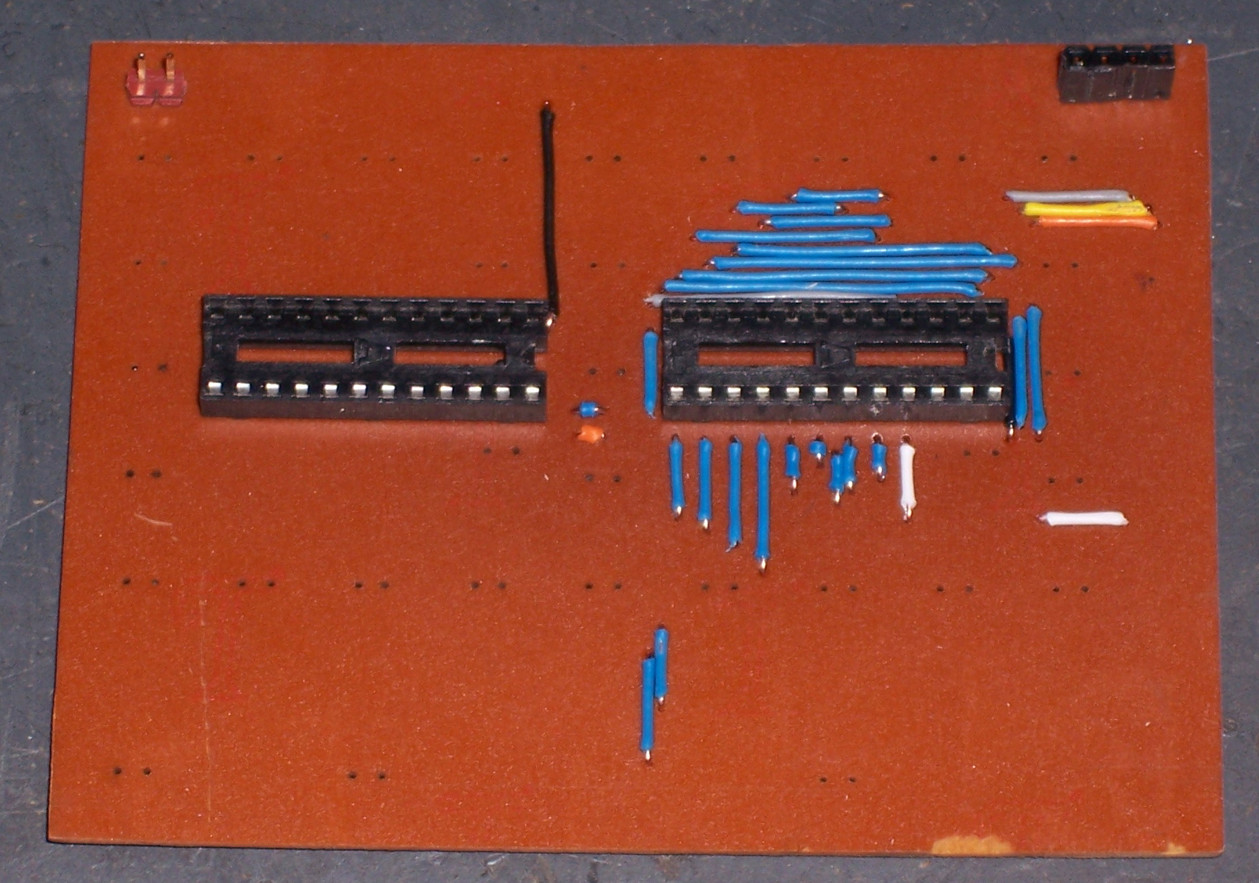
Notice how I left out the current-reference resistors, just below the right end of each socket in this photo? Don’t feel bad–I didn’t notice either, until I fired up the lights and they didn’t fire up.
Scuffing the LEDs
If you’ve been following the project, you may recall that I was only able to find clear LEDs with a pretty narrow viewing angle. I really wanted frosted LEDs, which have a softer appearance and wider viewable angle–the same difference as between clear and frosted incandescent bulbs. But I was only able to find clear for sale in bulk quantities and pricing.
So I improvised–I scuffed up the surface of a spare LED with 1500-grit sandpaper. It looked fantastic compared to the unmodified LEDs–a little dimmer when viewed straight-on, but much consistently brighter when viewed from different angles. Jeremy approved, so I ordered the clear LEDs and thought about how to scuff 360 of them once they arrived. Rock tumbler? Buffing wheel on the bench grinder?
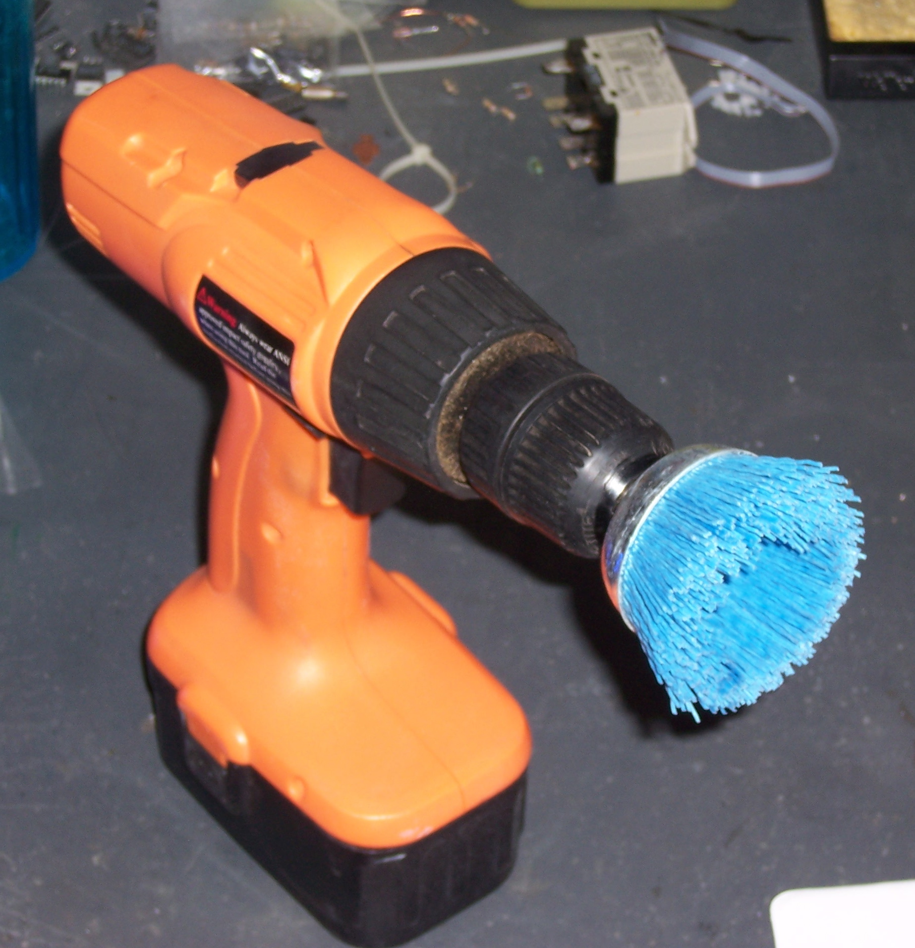
Fine-grit abrasive brush on a drill, as it turns out. It produced a really nice frosted finish on my first 31 LEDs, and I’m delighted with the process. I’ll want to chuck it into the drill press to do 360 of them, but it worked fine for a small batch.
LEDs Installed
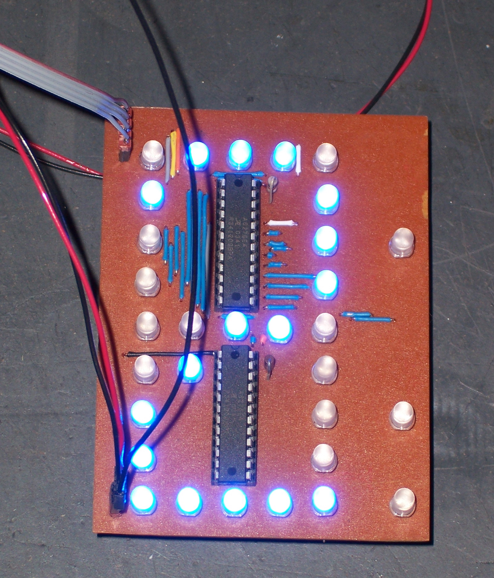
The LEDs installed nicely. The drill we used for the PCB was just the right size for the LED leads, so the LEDs are standing off about 1/4″ from the board where their leads are crimped. I had originally thought I’d want the LEDs flush with the board to help with alignment, but it’s a good test to see whether the alignment is adequate like this.
I had to fix a few small problems (missing resistors, missing trace, open trace, shorted traces), but all of those were construction problems. I was delighted to find that the board worked exactly as designed–a testament to the power of integrated schematic and PCB layout software.
Operational!
Next post: software, power supply, pics and MOV of one digit in operation. The LEDs are so bright, they even show up in a flash picture (above).
PCBex makes 61-80sqin single sided boards for $28/ea.
I haven’t used them in a while, but they delivered on their promises.
Doh, their URL would help…
https://maxima5.abac.com/pcbex/product_index.asp or http://www.pcbex.com/