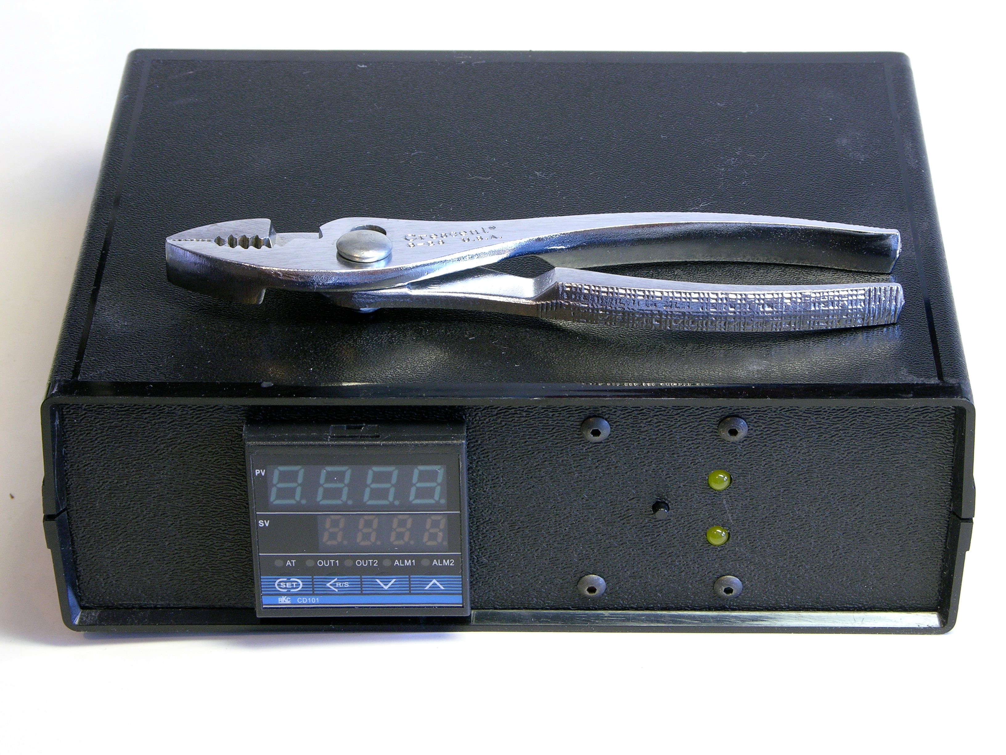
After assembling my PID crockpot controller, I successfully cooked a couple of medium KC strips at 60°C. When I tried to cook medium-rare at 55°C, though, I kept finding the temperature at 59°C. Not believing that I’m destined to eat medium steaks for the rest of my life, I want to fix this.
My first guess about what’s happening is that the crockpot is well-enough insulated that the controller’s longest delay for how often it turns on the heat is still too short. If so, I may get better control using the crockpot on its (dumb) low heat setting, which could be activated more frequently without driving the temperature as high.
Regardless, if I can’t trust the controller to control, I need a monitor external to the controller to let me know when the temperature has gone out of range so I know I don’t yet have a satisfactory system. Although the immediate problem was overheating, I should also like to know about undertemperature problems as well. Happily, the controller has temperature deviation alarms; but less happily, they are momentary and only show when the temperature is currently out of range. Enter the alarm latch.
Alarm Latch Board
I want to capture when the PID controller alerts that the actual temperature is above or below the target temperature by more than a threshold, and I want to latch the fact that the deviation occurred until I come pay attention to it and reset the alarm in preparation for the next error.
A simple S-R latch suffices for my needs and I had 74*279s in my parts bin. When a 74*279′s S (set) input goes low, the Q output goes high; when the R (reset) input goes low, the Q output goes low.
An S-R latch produces indeterminate output when both S and R are asserted at the same time — but as this would only happen if I were trying to reset the alarm while the deviant condition was still occurring, I don’t mind so much.
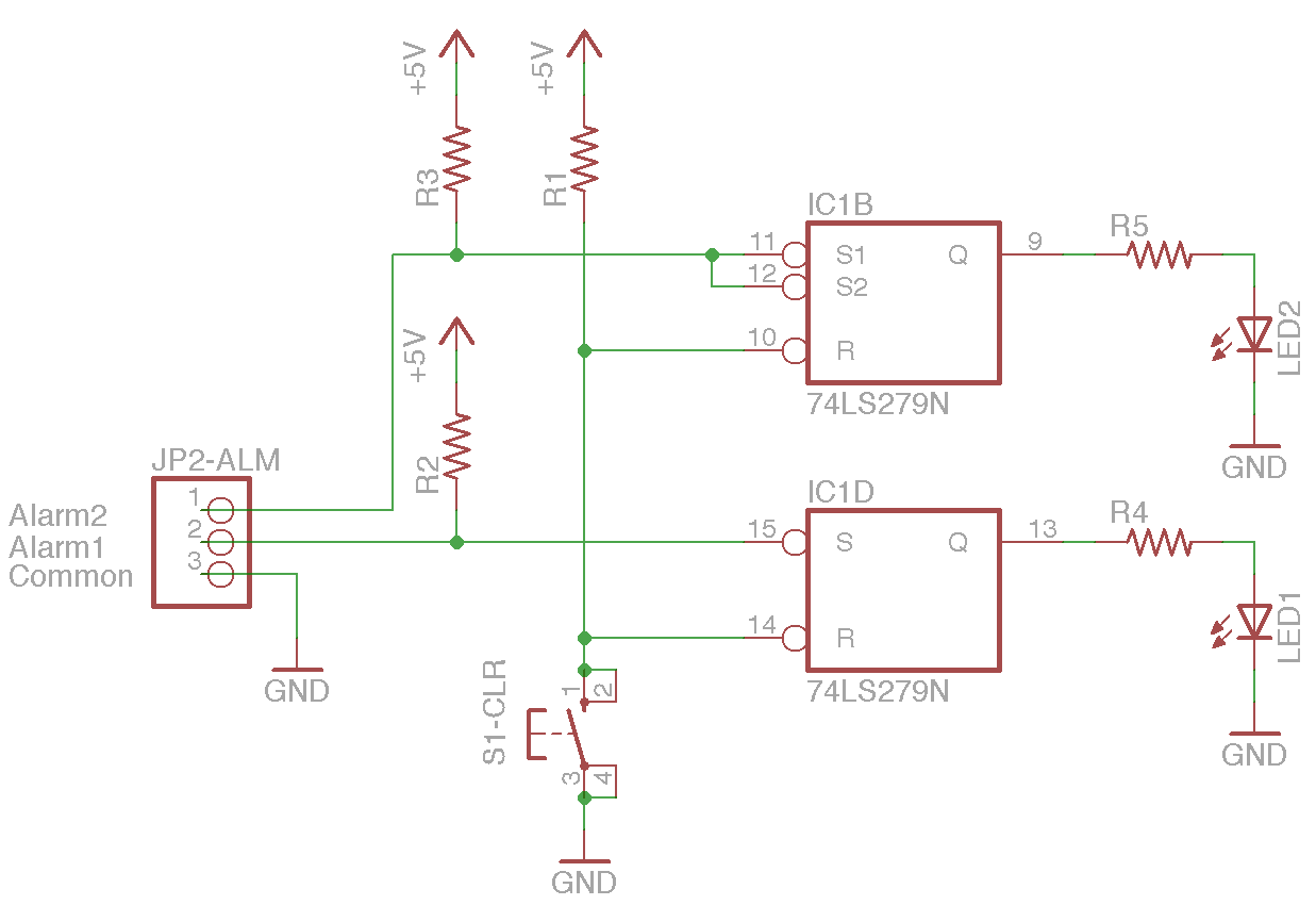
The PID controller has three pins for output alarms, labeled as ALM1 and ALM2 (both normally open) and common. From the sound when an alarm actuates, I believe these are implemented by small electromechanical relays.
In order to pull down the latch’s S input when the alarm triggers, I connected the PID controller’s alarm common pin to ground and put a pull-up resistor on each alarm line.
In order to pull down the latch’s R input when I press the reset button, I connected one side to ground and put a pull-up resistor on the reset line.
Milled, tinned, and assembled:
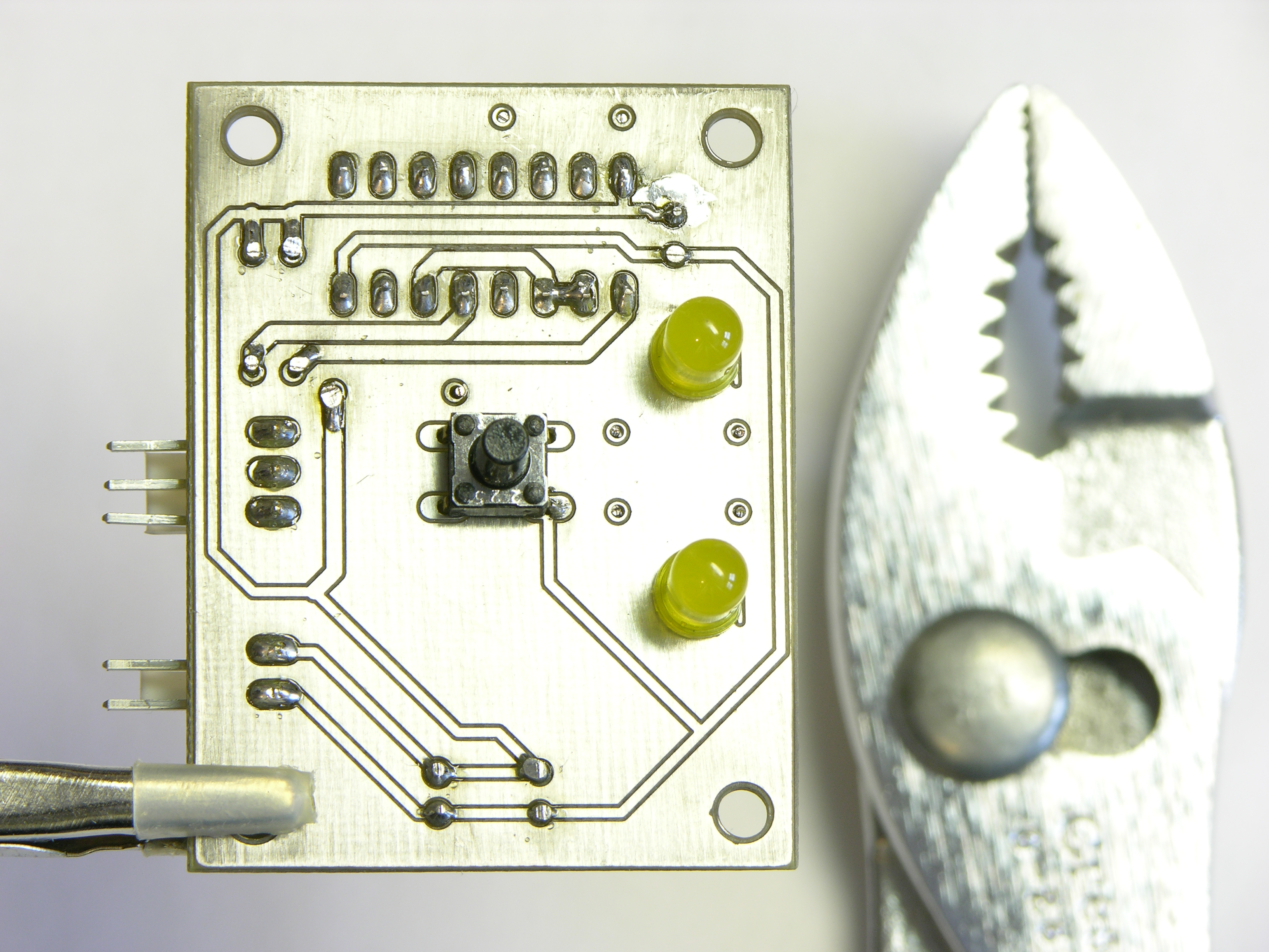
The outward-facing side of the board has the components that protrude through the front panel: the LEDs and reset button.
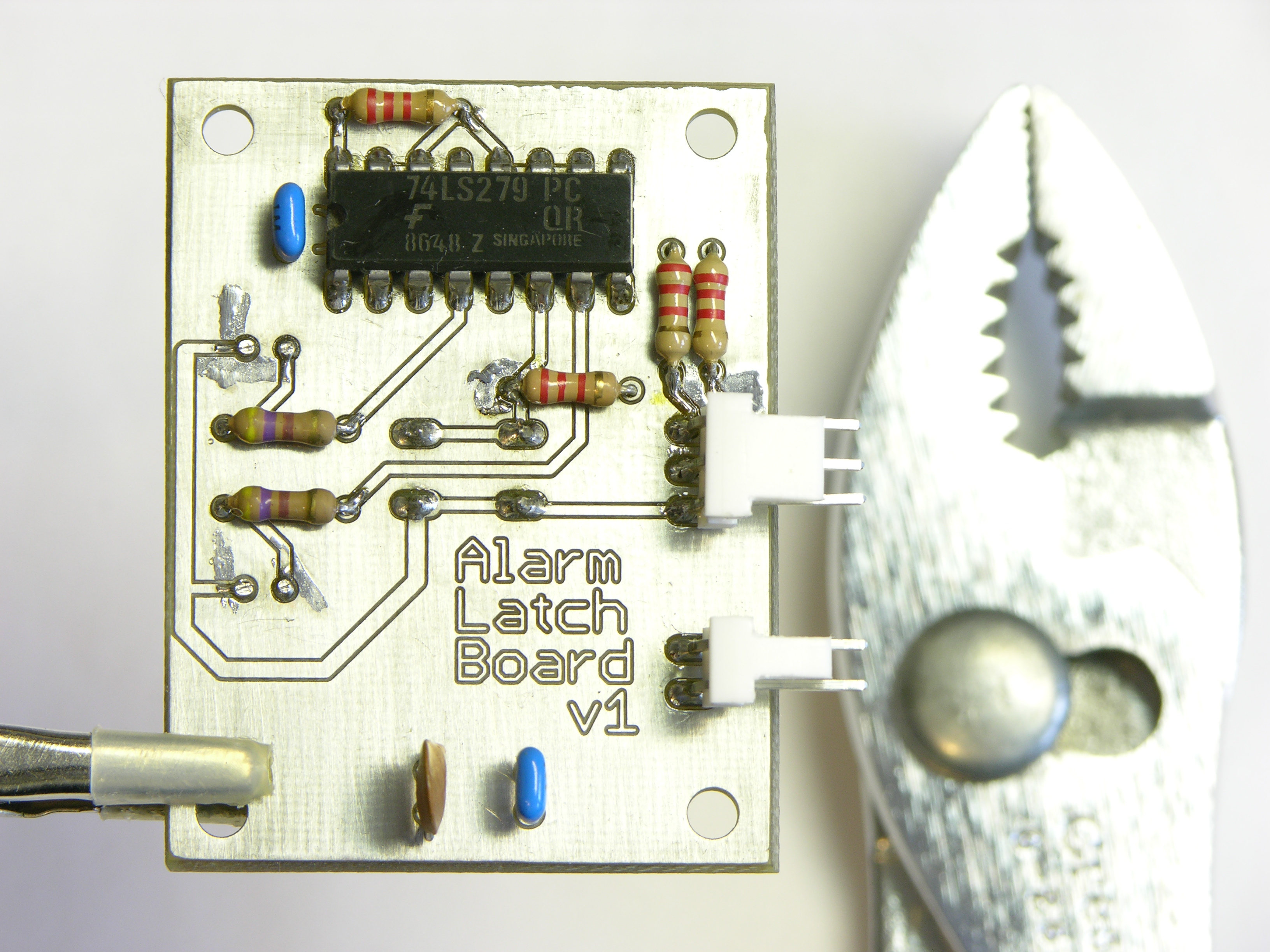
The inward-facing side of the board has everything else.
Lesson learned: Use bigger pads and smaller holes on milled boards. The small trace isolation and lack of soldermask make for very easy solder bridging; and the large, untinned gap between the pad and the component lead sitting inside an unplated hole occasionally makes for very difficult solder bridging.
Because of the bridging problem, I tested for (inappropriate) continuity after soldering every joint — it’s much easier to fix problems when I know exactly where the problems must be.
Rebuilding the Front Panel
I tried marking panel drill locations through the PCB’s holes with a center punch, but I’m a pretty poor machinist; zoom on the loose panel’s lower right mounting screw for a glimpse of only one of my many transgressions.
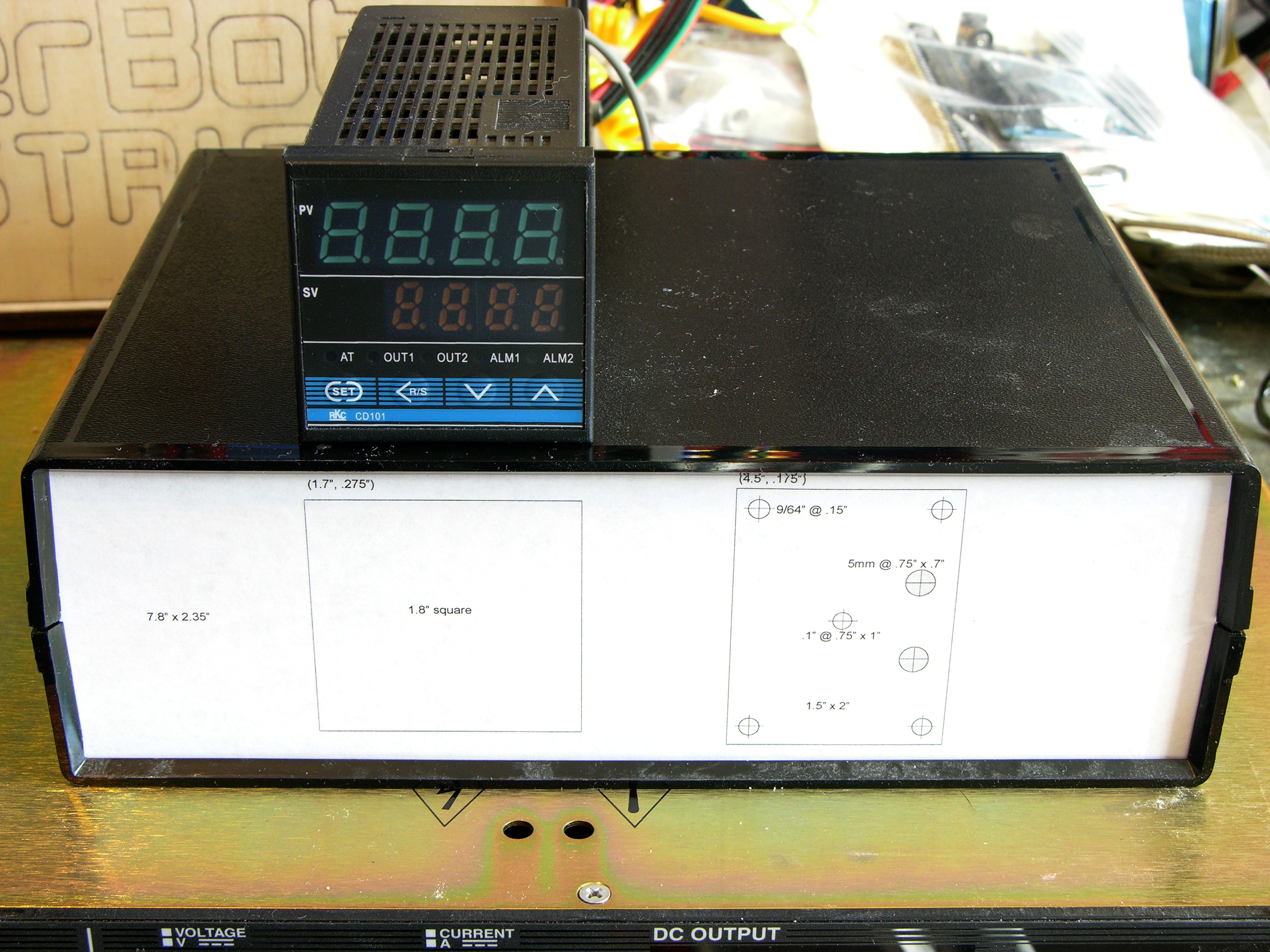
In an attempt to pretend I’m better than that (or, to reconcile my high standards with my low abilities), I laid out the front panel in OpenOffice Draw, printed it at 1:1 scale, and rubber-cemented it to a new piece of plastic.
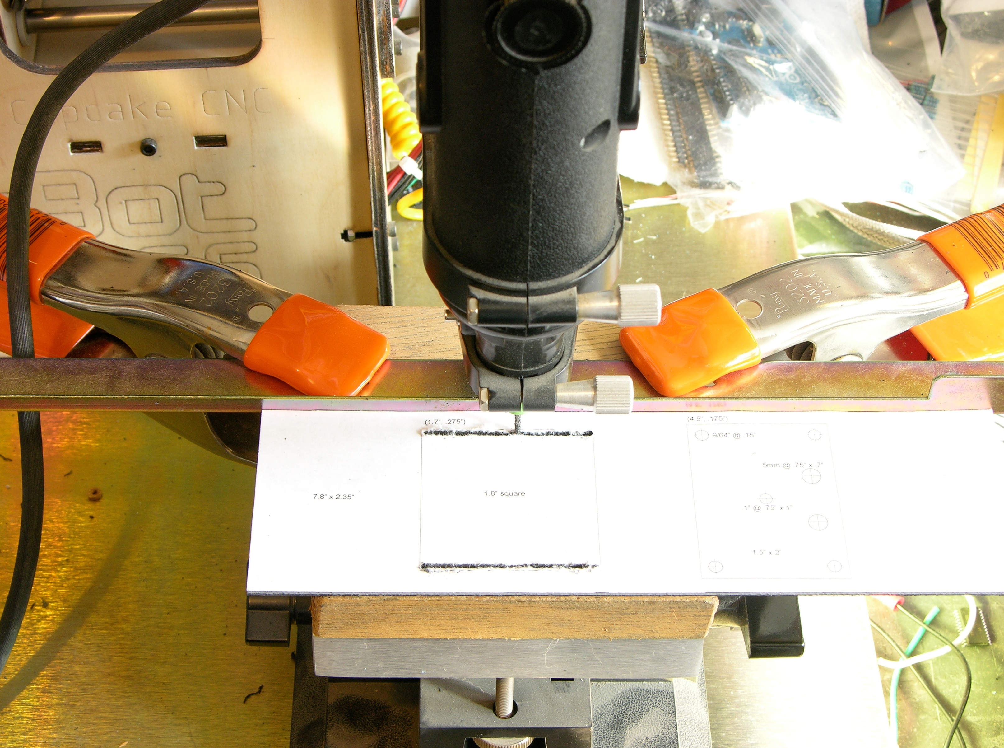
Rather than cut the PID controller’s mounting hole by running a knife against a rule (over and over and over and over) like last time, I ran the panel along a fence clamped to my Dremel drill press table in an impromptu vertical milling setup. (Yes, that is a routing bit.)
I knew that moving the workpiece from right to left would produce the cleanest cut but forgot it would also cause the bit’s rotation to pull the workpiece away from the fence. I practiced on a scrap piece (also known as the previous panel) and ended up making a L-R pass to cut and a R-L pass to clean.
I was able to drill my precisely-marked holes quite adequately on the mini drill press.
I so need a CNC mill.
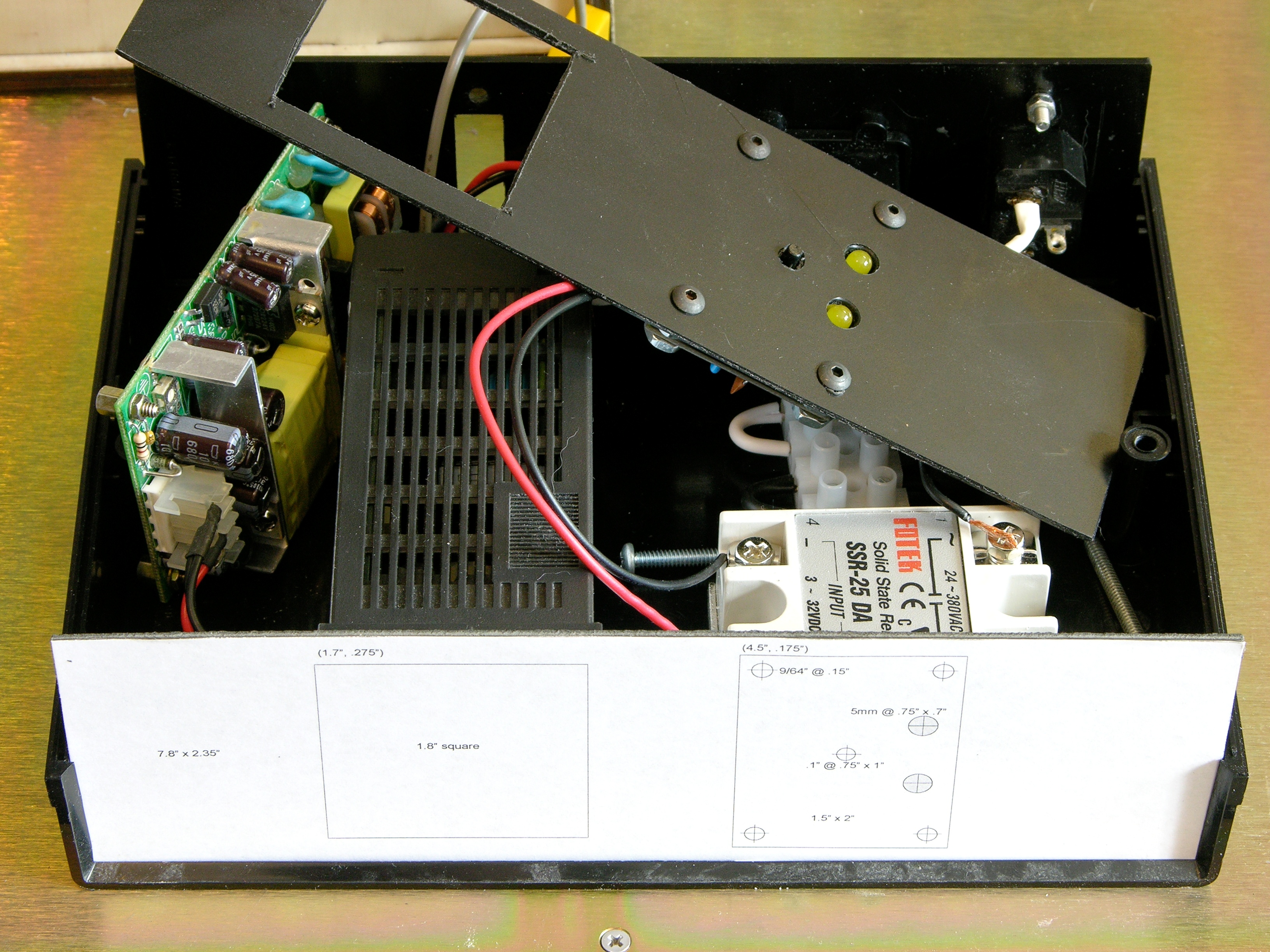
Controller (Re)assembly
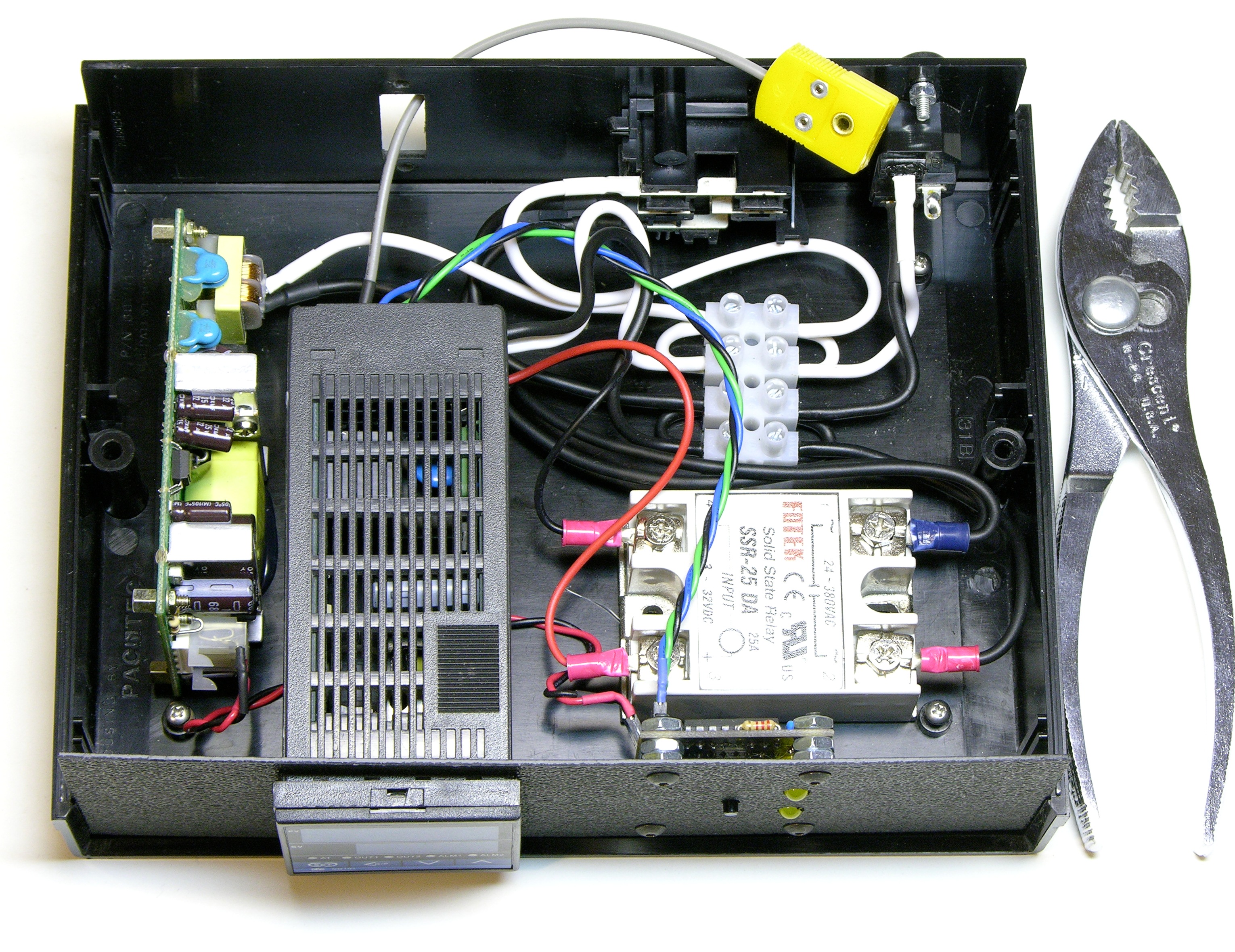
The TTL latch board necessitated the addition of a 5V power supply and the addition of a cutie 5V switcher module from eBay necessitated reorganization of the controller’s contents. Everything is now nicely hot-glued down and all the AC wiring is replaced with new 16-gauge. (I was surprised no one commented on the temporary undersized wiring in my first assembly.)
The PID controller’s ratcheting collar that’s supposed to clamp it to the panel is a little too big to fit inside the case, so the controller wasn’t quite rigid with respect to the panel. A couple of rubber feet stuck to the interior of the case top and bottom grip it in position quite nicely.
I also bought some thermocouple jacks so I no longer have to screw its connector pins into the old barrier strip every time I use the crockpot. Need to design and print a nice panel-mount bracket for the jack.
So?
Erm. Yes. Does it work well.
Forgot to update inputs
The schematic shown here is not in fact what I constructed. Because I still remember when ICs could sink more current than they could source, I’m in the habit of wiring LEDs between VCC and an output rather than between an output and ground, and that’s how I initially drew this circuit. Consequently the alarm lines were then connected to the R inputs so that the alarms would reset the outputs to low, turning on the LEDs.
Then I had the presence of mind to test whether the 74*279′s outputs were predictably high or low after being powered up and before inputs were applied (the power-up state is not guaranteed); and lo!, they boot low.
How sharper than a serpent’s tooth would it be to have to press reset every time I powered on the controller, methinks, knowing that I could have wired it so I had not have had to. So exeunt LEDs to VCC and enter LEDs to ground.
Alas, I failed to exeunt omnes and instead left the S and R inputs as they were; so now my controller powers up with the LEDs off, I press reset, the LEDs come on, and I curse the fool who laid out the alarm board.
Actual PID controller alarm capabilities

Lo!, were this my only shortcoming, I would praise the day of my good fortune; but some fool also neglected to compare the actual model of PID controller he owned with the capability list in the datasheet — the list, that is, of which of the controller’s copious possible capabilities are actually present in the particular controller owned by the fool.
Such as, for example, the presence of (oh, I shudder even to type these words) only one alarm implemented in my controller.
Some fool also failed to test the alarm feature before building an external latching board. Had he done so, he might have discovered that in spite of the controller being quite clearly labeled as a model with “Deviation high alarm,” not “Deviation high alarm with hold action,” it appears in practice to have hold action.
That’s right — not only are the LEDs on when they should be off; but one of them will never do anything; and the entire latch board is superfluous because the controller’s onboard LEDs, in spite of the designation on the datasheet, latch.
Sigh.
At least after all this, I can still know — as planned — when the temperature climbs above the target. I am cooking some lukewarm water for dinner right now.
Hi there,
I’ve found soldering milled boards works much easier if you use Kapton tape as a buffer so the solder doesn’t wick. You can see what I mean here: http://www.fromorbit.com/content/finished-smd-ring-oscillator
I’ve had great success with it and I just keep reusing the same pieces until they don’t stick any more.
Cheers,
Alan.
Alan, looks like a great tip for SMD work on milled boards!
Unfortunately my worst bridging problems were around through-hole pads, which would be more challenging to mask off with tape. Taping the board before milling and then peeling the tape off the traces (leaving it on the isolation) seems vaguely interesting, though …
We’ve been using the same controller successfully until the worst possible moment! We had a table at the Kitsap Mini Maker Faire in Poulsbo, Washington and were going to serve sous vide eggs as a demonstration of the technology.
Six dozen eggs went into the turkey fryer the night before the fair. And we woke up to six dozen extremely hard boiled eggs! The PID controller had failed with a flashing o o o o on the display and the output full on!
That error indicates a failed thermocouple. A quick swap-out with a new T/C and the error was the same.
A failure with $10 of eggs isn’t so bad, except for the Murphy’s-Law timing of it, but if it had been a nice piece of beef, the damage could have been far worse.
Here’s a brief article about the failure and the fair:
http://digital-diy.com/Electronics-Blog/the-kitsap-mini-maler-faire.html
I suspect that whatever great programming fails with the output on may fail to turn on the over temperature alarm too….