Last weekend I got my Dremel rigidly mounted in my CupCake for PCB milling, but the platform holding the PCB was attached with double-stick foam and was being deflected by the milling bit cutting the copper, causing considerable deviation from the intended milling path.
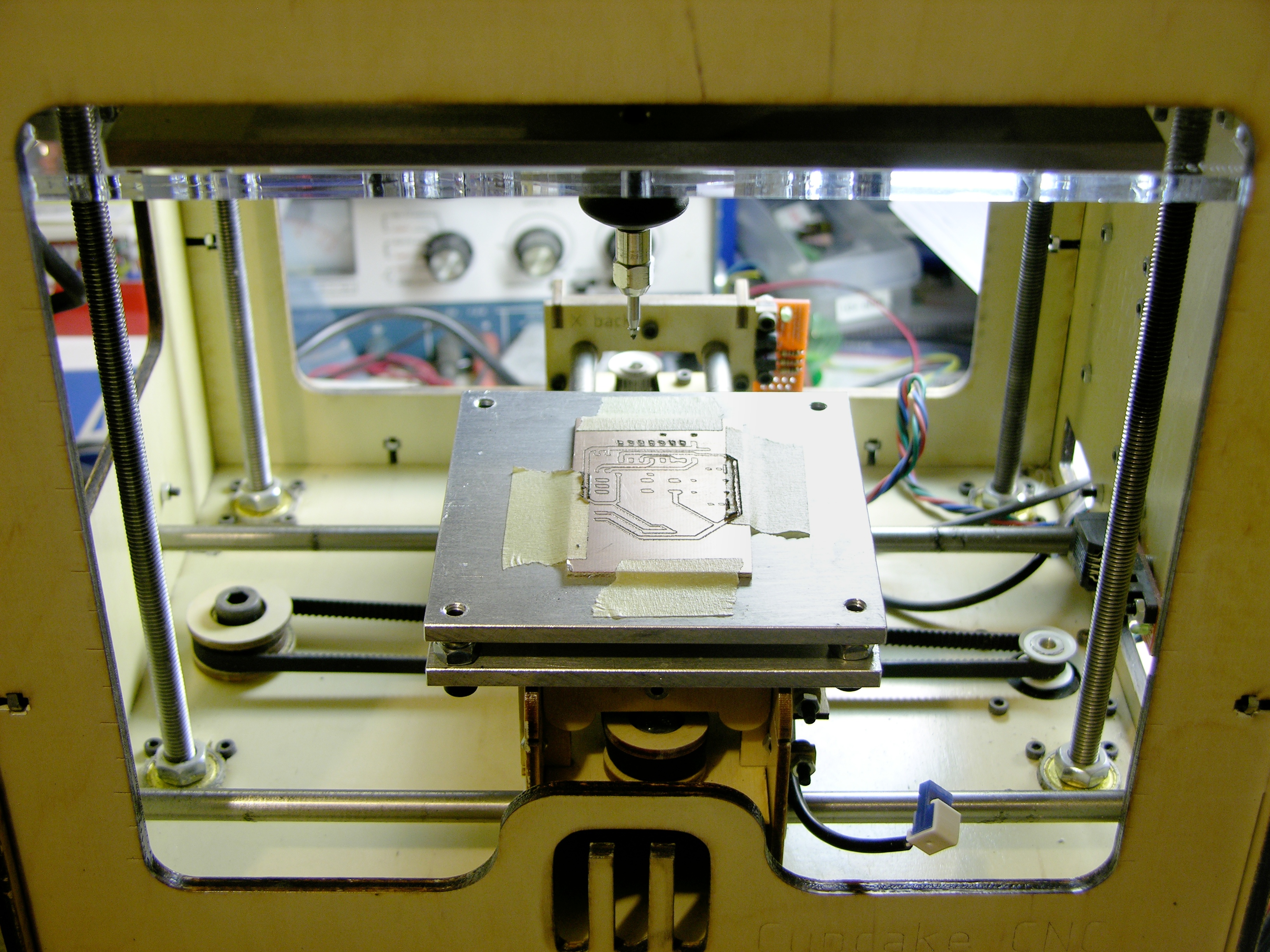
Last night Steve cut some more aluminum plate for me and today I assembled a rigidly-mounted leveling platform to replace the stock build platform. The lower plate has holes matching the machine screws attaching the top of the Y stage, and I used slightly longer screws to bolt through both the aluminum plate and the original wood top into the Y carriage.
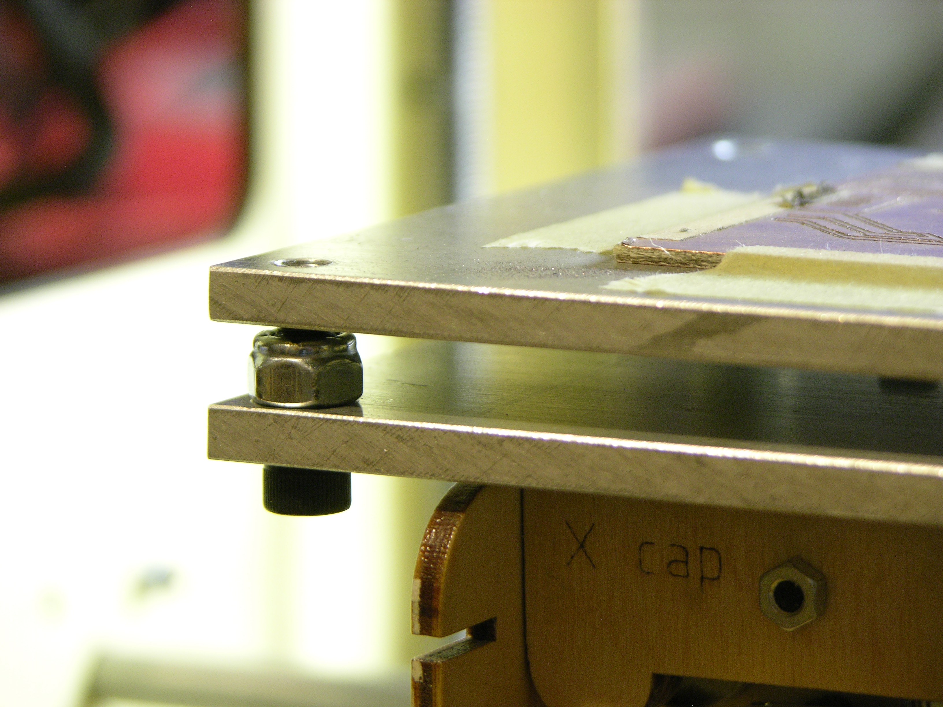
I drilled holes in the corners, tapped the upper plate, and enlarged the holes in the lower plate. The socket-head cap screws spin freely in the lower plate while adjusting the upper plate’s height (I used a continuity meter to check when the milling bit was just barely touching the plate in each corner); then the nylon-insert nuts lock the screws in position. The whole assembly is quite rigid once tightened.
A number of designs for leveling build platforms use only springs between the two plates. I was concerned that without a nut, the machine screws might back out under vibration. Also, when extruding, having a platform with some give reduces the damage if you miscalculate the Z position and gouge the platform; but for milling, the whole point of this replacement is to remove any play in the platform.
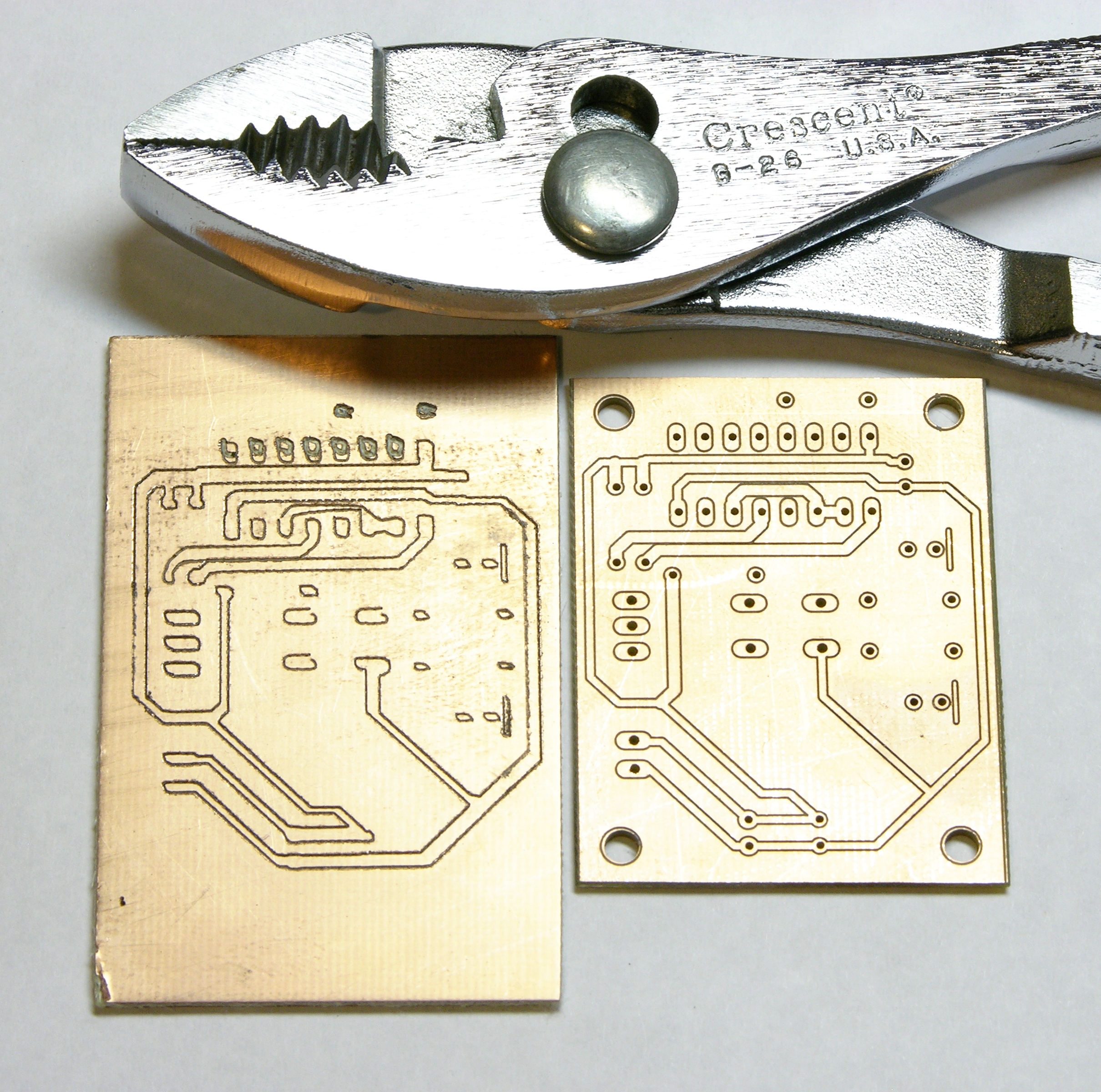
The results were not tremendously better than before (left board, top row of pads; right board from commercial mill for comparison), so I slowed the feed rate to .1″ per minute and let the mill finish the rest of the board for five hours, just to see whether I could produce usable traces. The traces cut at an outrageously slow feed rate are much better than previous results, but still a bit, shall we say, interpretive for my taste.
Having watched the Dremel bit trying to cut the copper and having tested it handheld out of the machine, I do recognize that it’s not the right bit for this job. I have some carbide engraving bits recommended by Pierre (exuinoxefr) on the way from Hong Kong, and I think they’ll make a significant difference. In April.
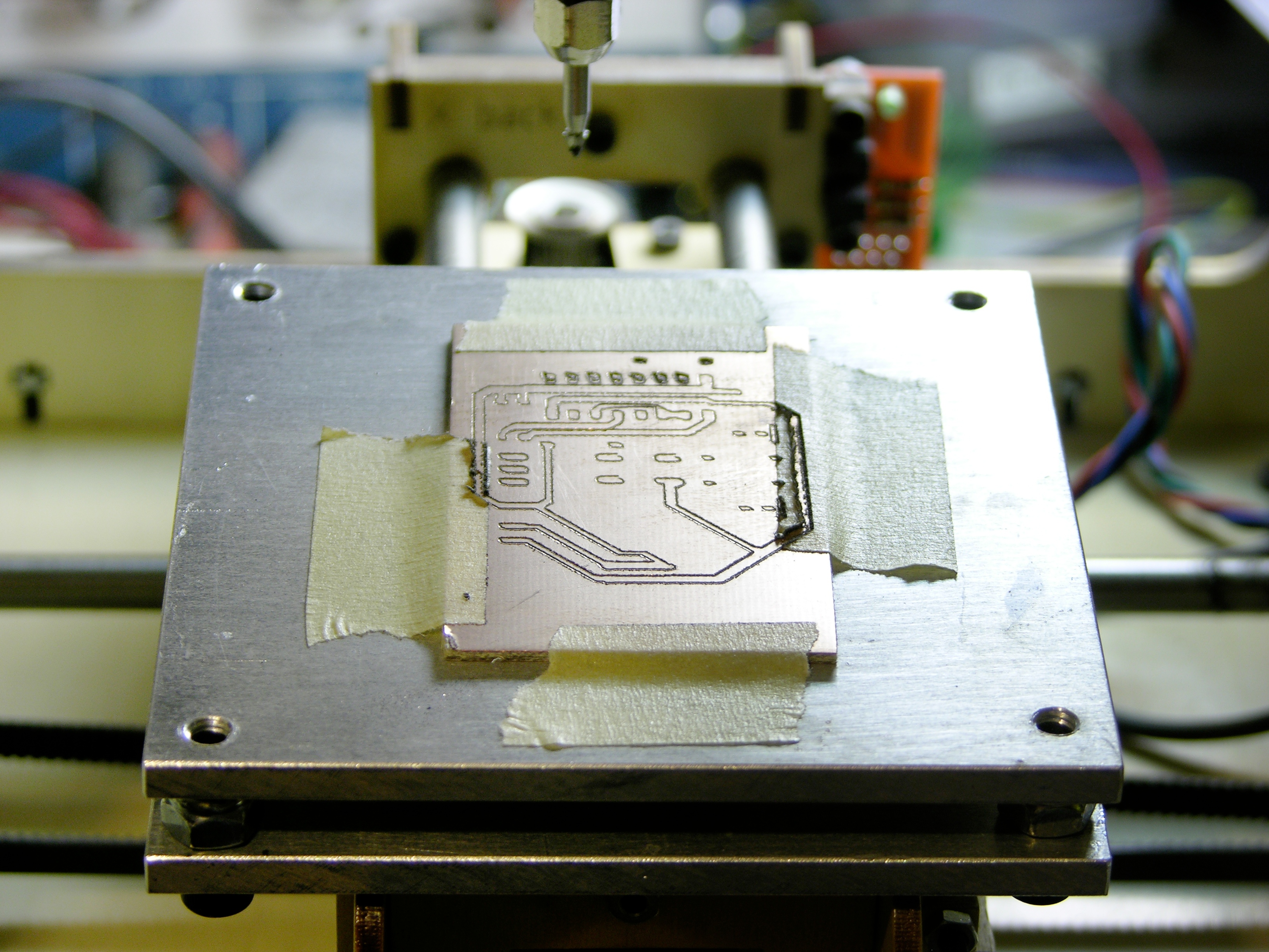
Meanwhile, note the three pads in the center of the board. Even at only one stepper motor step per second, the board took a very consistently incorrect path under the toolhead. Also note that the diagonal lines look like they were drawn with a left-handed quill pen — NE/SW lines are thicker than NW/SE.
I believe this is caused by the considerable play between the original CupCake bushings and the guide rods. Tighter bushings would cause more friction, so they were chosen for a bit of a loose fit. Even though the platform is now rigidly mounted on the Y carriage, the Y carriage wiggles on the Y guide rods and the X-Y carriage wiggles on the X guide rods.
I’m extremely interested in the Mendel-inspired replacement X-Y assembly by Thingiverse contributor “twotimes.” It replaces the bushings with sets of roller bearings spaced around the guide rods; the bearings can be tightened against the rods and still roll smoothly. I intend to get in touch and ask whether it successfully removes the play from the carriages.
Although my immediate interest is whether I can use the CupCake that I already own as a PCB milling machine, the enhancements I’m making will improve it as a filament deposition machine as well. The lack of leveling in my heated build platform prevented me from printing larger models; I’ve already drilled my heated platform to fit interchangeably into this new system. Smoother X-Y action from a replacement carriage can only help, too.
I’m so glad you’re doing all the hard work for us so when you finally get your cupcake milling smoothly we can just replicate the finished product – thanks Keith!
I’ve used a standard end mill to make several PCBs on a MaxNC Mill at Noisebridge. The best part is that they’re cheap and available on Amazon: http://www.amazon.com/Niagara-Cutter-059918-Overall-Carbide/dp/B000N477OK/ . Neat project, hope this helps!
Oh man, Richard, you totally stole my comment! Keith, I love what you’re doing but no way to I have the chops to work with physical stuff like that. It’s on my list for some day but I gotta finish this guitar amplifier design first!
John, you say that, but I’m telling you I have no machining chops. I’d be cutting my aluminum with a hacksaw if my friend Steve didn’t have an aluminum-cutting circular saw blade; drilling holes requires a drill press; and I’m using a hand-operated tap to thread the holes.
To quote Garth Pancake, “Easiest thing in the world!”
Chops maybe isn’t the right word. I don’t even know what I don’t know at this point. I’m still doing stuff with wood (cigar box guitars & cigar box guitar amplifiers at the moment) and hopefully when I get more experience with that I’ll move on to metal.
Meh. I’m too timid, and too afraid of making mistakes, and that’s probably my problem. When I get more time I should jump in to this stuff feet first.
Yes, the movement in the mechanism could be causing the NW/SE issue. Look also how the spindle rotation relates to the direction of travel, you might be climb milling in one direction.
http://wsshd.com/ehRWw2
You might find that the next limitation will be the dremel itself, I’m not how much flex there is in the bearings of that.
you have a backlash problem with your mill. That’s why some of your traces are wider than others in different directions.
tlab, backlash is also known as lash or play, which is exactly what I describe and attribute to the looseness of the X-Y bushings and guide rods. Am I missing something, or were you trying to convey a different angle on the problem?
As i’m looking at the bit you are milling with I got the feeling I have to share these bits with you:
5 x 45° Carbide PCB Engraving Bits CNC Router Tool #T14
http://cgi.ebay.com/5-x-45-Carbide-PCB-Engraving-Bits-CNC-Router-Tool-T14-/250522253434?pt=UK_Home_Garden_PowerTools_SM&hash=item3a544a387a
5 x 30° Carbide PCB Engraving Bits CNC Router Tool #T13:
http://cgi.ebay.com/5-x-30-Carbide-PCB-Engraving-Bits-CNC-Router-Tool-T13-/250522255776?pt=UK_Home_Garden_PowerTools_SM&hash=item3a544a41a0
I, as a hobbyist using them all the time for milling PCB’s and the result is very neat (http://jjshortcut.files.wordpress.com/2011/02/18022011074-1024×768.jpg), the tool you use is more a grinding tool and not really a engrave tool. You could also use a endmill as said by Josh M, I used them to because I did not my table leveled right but since you already cleared that problem you can use engrave bits.
Good luck!
A suggestion for your leveling system: instead of using four screws, use three.
Four screws give you what’s called a ‘redundant constraint design’ — one that inherently puts warping or binding stresses on the parts. In this case, one of your four screws is more trouble than it’s worth.
Any three points define a plane, but there’s no guarantee you’ll get the fourth point in exactly the same plane as the first three. You’ll probably end up putting stresses on the top plate that cause it to warp.
The good news is that switching to a three-screw design is easy: just drill another hole in the center of one side. Remove the two screws from the corners on that side and move one of them to the middle.
Three screws can’t warp your plate, and they’re easy to adjust: set your working height with the screw in the upper-left corner, level the edge of the plate by bringing the upper-right screw to the same height, then level the whole plate by bringing the bottom-center screw to the correct height.
You can Google ‘three screw level’ for pictures of similar systems, and instructions on how to use them.
All I can say is that yes, the stock Cupcake bushings define “loose” and that is at least some of the problem. I have a printed twotimes lowrider assembled and it will remove all the slop out of the machine for sure. You definitely want to do this. If you want, you can PM me (on the MBI forum) and I will sell my working assembled version for $25 to cover the cost of the bearings in it. I also found the stock rods were soft, and the hard bearing surfaces actually pitted them over time, so I have super hard piano wire rods and use a small dab of lube on them. This will get you back to accurate movements!
Next up is the Z axis and I’m not yet sure what is the best method on that for you. You defintiely need more strength there too.
The X/Y lowrider from twotimes is a great addition to a Cupcake and will indeed make your X/Y movements a bit less wobbly.
Another VERY good mod is the PSMD board from Rob Giseburt: http://www.thingiverse.com/thing:4526 . If nothing else, that’ll get you 1/16th X/Y stepping instead of the 1/2 (1/4?) stepping that Cupcakes come with.
Dave, have you used microstepping with the CupCake? I have the Pololu stepper boards on hand and was considering using them but was concerned about the CupCake’s CPU. As it’s already taxed doing the calculations for g-codes, I wondered whether it would become overtaxed doing calculations at higher precision and controlling many times more steps.
Yup. I’ve got Aaron’s X/Y low-rider and Rob’s PSMD on my Cupcake. And a MakerGear stepper extruder. All with gen3 motherboard and extruder controller.
I’m not sure that going to 1/16th stepping actually increases the load on the CPU. It’s just taking the gcode (which skeinforge created) and moving the steppers the right number of steps. I don’t think it cares if it takes 100 steps or 1000 steps to move an inch. (I could be totally wrong, though)
You might want to also take a look at http://www.thingiverse.com/thing:4239 , which adds bearings to the X axis. It’s not quite as nice as Aaron’s lowrider but it’s a far easier print and will give you an idea how much improvement you’ll get by using bearings instead of bushings..
mas, my aluminum plate isn’t milled; it’s straight from the scrapyard. Three screws would be fine if I had a flat plate; four screws work perfectly to level this plate.