My dashboard solar charger is one of the more useful things I’ve bought from Harbor Freight. My van has some weak short-circuit and slowly drains the battery, and as I don’t use the van all that often, I was at risk of coming out to a completely drained battery. I now keep one of these on the dash and the battery is always topped off. When I first connected it, the van was sitting in shade and the (old) automotive battery measured 5V (!); after a week it was up to 9V and after another week it was fully charged. Now I don’t ever have to think about a drained battery again. At about $20 list and $15 on sale, it’s a steal.
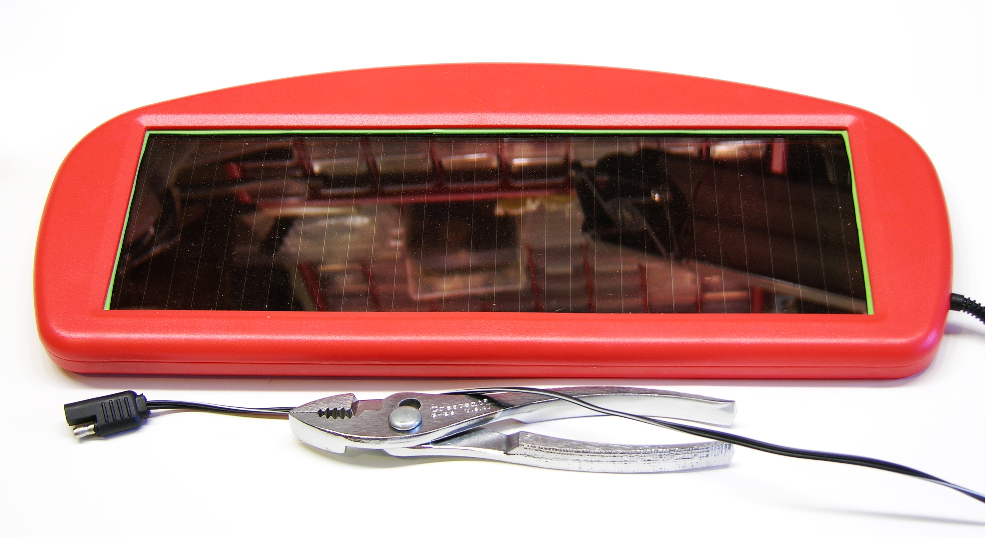
The bus conversion project is languishing but not forgotten, and I’ve been wanting to put one of these chargers into the bus for the same reasons as I had for the van. The wiring situation is a little different, though — the bus has no cigarette lighter / power port, I’m intending to wire 12VDC throughout the bus with Anderson power pole connectors, and I might like to have multiple solar trickle chargers (even before I install larger solar panels on the roof).
The issue with multiple panels, and even with a single panel connected to a battery that will also be charged by the alternator, and even with a single panel that may still be connected to the battery at night, is that photovoltaic cells don’t like to have reverse voltage applied. The photovoltaic effect happens in a semiconductor junction, and although I can no longer find the reference I was reading the other day, I still know the cell doesn’t do well with a reverse voltage and should really be diode-protected.
Because I wasn’t sure how much (if any) circuitry was in the panel and how much (if any) was in the automotive power plug connector, I had to take both apart to (A) make sure the panel would be diode-protected even after I chopped off the power plug and (B) see whether either held any relevant / useful circuitry.
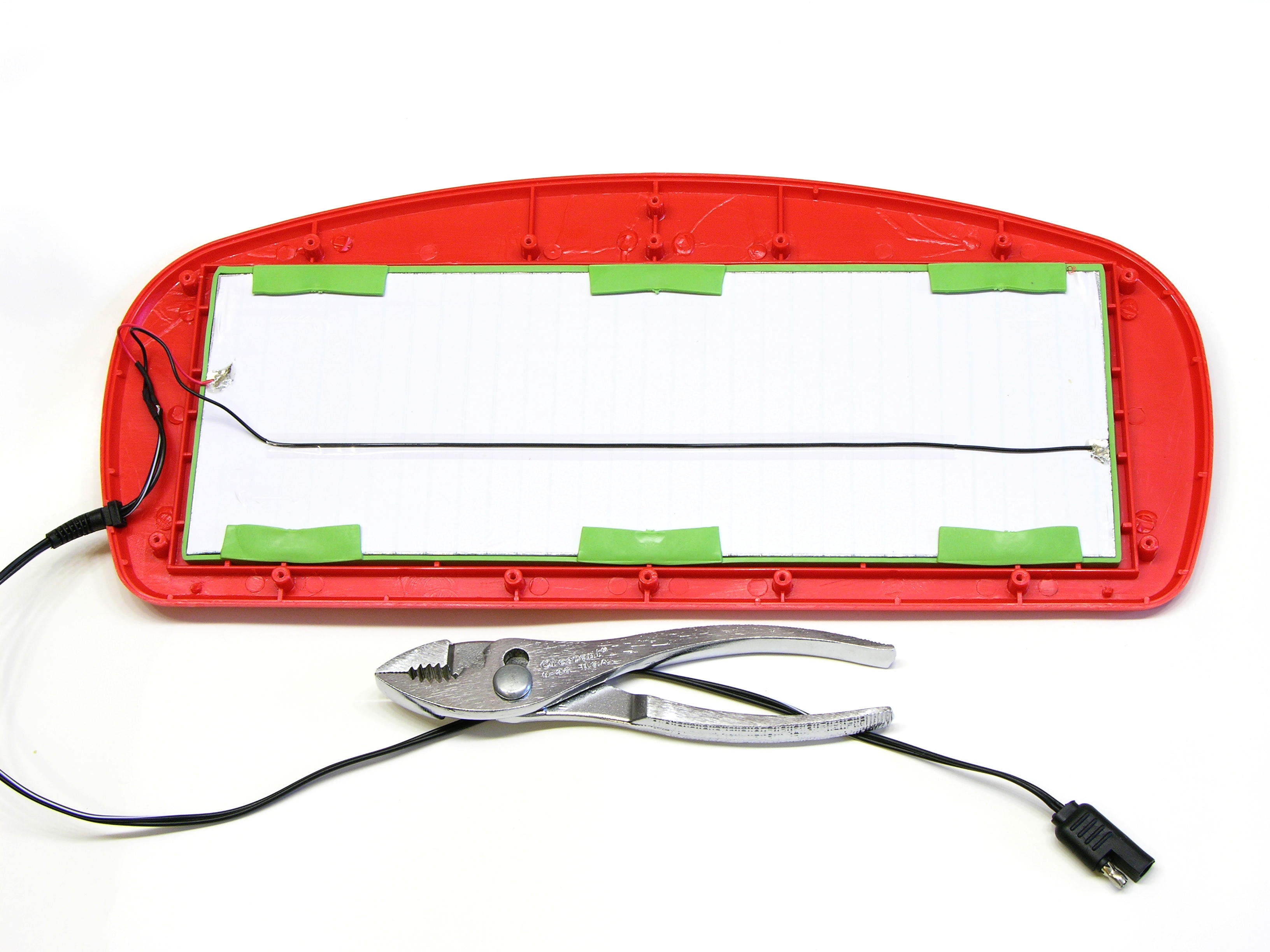
Panel — nope, nothing there.
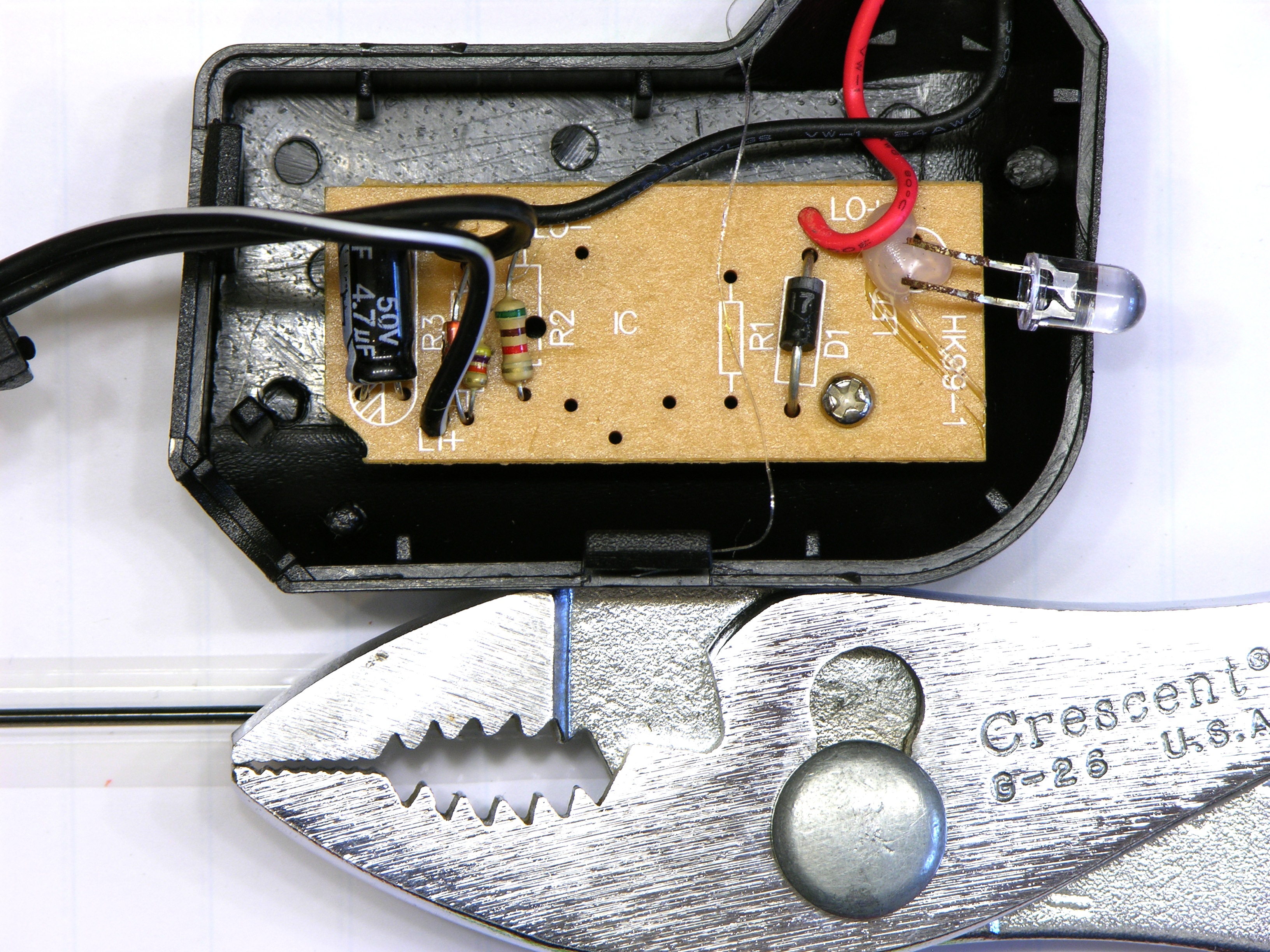
Power plug — the LED that flashes while light is falling on the panel, a rectifier diode, and some passives.

Oh, and an integrated circuit under a glob of epoxy.
Hm, will that be some sort of power conversion or regulation circuit, or just the LED flasher?

The ground wire comes in from the panel, is soldered to the board, and connects to a ground wire running to the plug’s sleeve terminal. The positive wire comes in from the panel, is soldered to the board, and connects to the rectifier’s anode; the cathode connects to a positive wire running to the plug tip. The epoxy blob is therefore just the LED flasher.
The flashing LED is kind of a nice indication that the panel is delivering power to the battery; but I’m going to dispose of the plug; it’s not worth transplanting the PCB to the panel enclosure; and I can tell it’s making power ’cause I can see there’s sunlight falling on it. Also, something in this unit is flaky and the LED sometimes doesn’t flash even when the unit appears to be working.
So I need to chop off the whole power plug and wire in Anderson power poles, and somewhere in between the panel and the connector I need a protection diode. Might as well use the one from the circuit since it’s free, and it turns out to be a 1N5817 Schottky. The Schottky’s fast turnaround time isn’t important for this application — it would have been selected for its low forward voltage drop of .45V @ 1A and about .3V @ the 120mA for which the panel is rated.

Put the diode inline in the power cord or move it inside the panel? Since the diode is there to protect the panel from damage, I’m of a mind that it should be integral to the panel assembly — hard to separate and hard to bypass. There’s lots of room inside the case, so I moved the diode there and enclosed it in heatshrink.
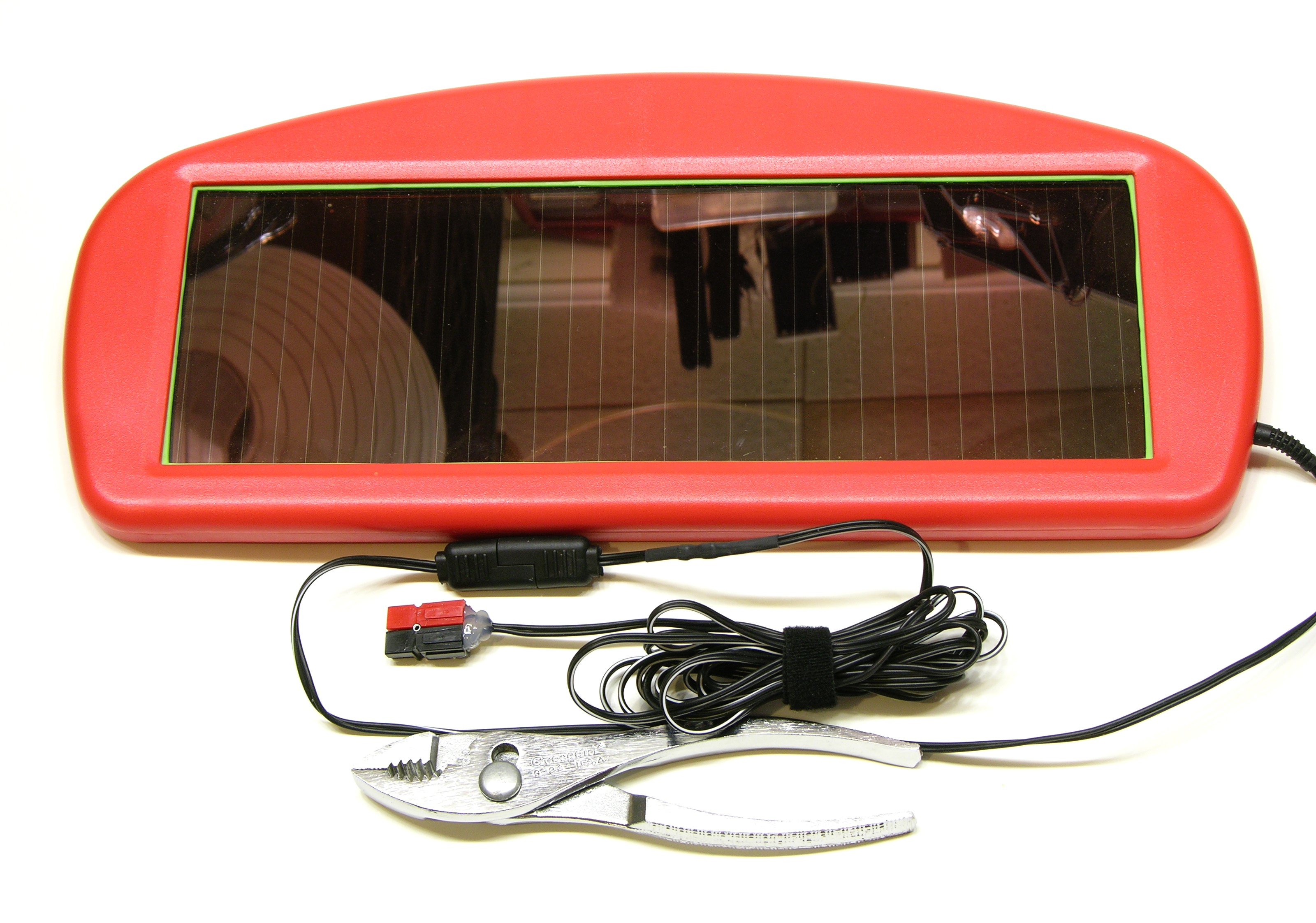
Anderson power poles (the red and black connector at the center) are genderless connectors with generous metal-to-metal contact suitable for fairly high-current applications and popular in the amateur radio community. The individual shells have notches in the sides to slide together into whatever configuration of multi-pin connector you want.
And because they’re genderless (rotate the connector 180° and it would plug together with a connector sitting in its original position), they’re great for batteries — put the same connector on the battery, the battery charger, and your load, and you can pick any two devices to plug together.
This suits my plan for the bus: run appropriate-gauge DC wiring throughout and anywhere there’s a drop, I could plug in an AC or solar charger, a 12VDC light, an automotive USB charger, etc. Even before I do all the wiring, it still pleases me to have a cable coming from the battery into which I can easily plug the solar trickle charger, a small power inverter, or a USB charger.
My one concern is that everywhere I’ve seen power poles, red/black has been used for 12V connections; but the Anderson color code chart lists that red signifies 24V and yellow should be used for 12V. Yellow is a lot harder to find, not only in use but also to purchase. Although it seems important to conform to Anderson’s de jure standard of yellow/<what?>, I think using anything other than the de facto standard of red/black risks confusing anyone else familiar with power poles.
I am a firm believer in PowerPoles, I have my amateur radio station and computer desk wired with them using colors and configurations to separate the various voltages. This site and a few others you can find in QST have the colored shells “À la carte”;
http://www.hamcq.com/powerpoles/powerpole-connectors/cat_71.html
I am using orange and black for 5V with the orange “below” rather than to the “left” of the black. That helps avoid letting the smoke out accidentally.
I’ve got some very similar looking pannels I bought from Maplin in the UK, I’ll have to see if they also have a pointless PCB in them.
Is it possible that the LED only flashes when the panel voltage is above 12.6V? Just wondering if that may be the reason that it flashes intermittently.
Don’t worry too much about the color code. The electrons do not care and most everyone in the world will assume red/black is 12V.
I don’t suppose your vehicle has an older LoJack installed on it? If so, your battery (on the LoJack) may be DOA like mine was — it was causing it to completely flatten my trucks 12v battery to the tune of about 900ma — 24 hours a day.. I tracked down the LoJack and removed it — problem solved. My neighbor’s Mustang suffers the same affliction — he’s not had a chance to remove the circa 1995 LoJack on his yet.. YMMV!