Necessity is said to be the mother of invention, and 90+°F daily temperatures with the air conditioner on the fritz made me feel pretty inventive.
Our air conditioner was low on refrigerant and the blower fan motor may be running slower than spec and not moving enough air. Between the two problems, the expansion coil inside the furnace housing would ice up, over a few hours completely blocking the airflow and preventing any meaningful heat exchange. I’d then have to switch off cooling mode and run only the fan for a few hours to melt the ice.
On a weekend when I was home all day, I discovered that I could keep the house fairly cool by setting the blower fan to run all the time, manually monitoring the airflow out the vents, and cycling the AC off when airflow was restricted and back on when it opened up. Which sounded like a perfect job for a microcontroller.
Introducing the scungy anemometer, or Airduino v0.1, for short. Also introducing real-life code using the Arduino’s external interrupt pin(s).
Measuring Airflow
My thought was to stick a propeller into the airflow and measure its rate of spin with an optoreflector. Some people have used brushless PC cooling fans and measured the electrical impulses, but I didn’t have any. And I tried blowing air into spare PC (DC motor) fans, but their permanent magnets made them all too stiff to turn.
Knowing I wanted something light and easy to move, I folded aluminum foil into a four-layer rectangle for rigidity, twisted it to make a propeller shape, and stuck a pin through the middle. Holding it in front of an AC duct, it spun freely and rapidly, so I figured it was a good start.
Next, I hoped to use an optoreflector pointed at the propellor to measure rate of spin. An optoreflector has an LED (usually infrared) and a matching phototransistor pointing in the same direction, so it can detect when the light is being reflected off a nearby object. (An optointerruptor has the LED and phototransistor facing each other with a slot between them, to register when something passes through the slot. I don’t know of any commercial optointerruptors with a slot wide enough for my foil fan blade to pass through.)
I had this big bag of optoreflectors and optointerruptors from Slim, so I figured I was golden.
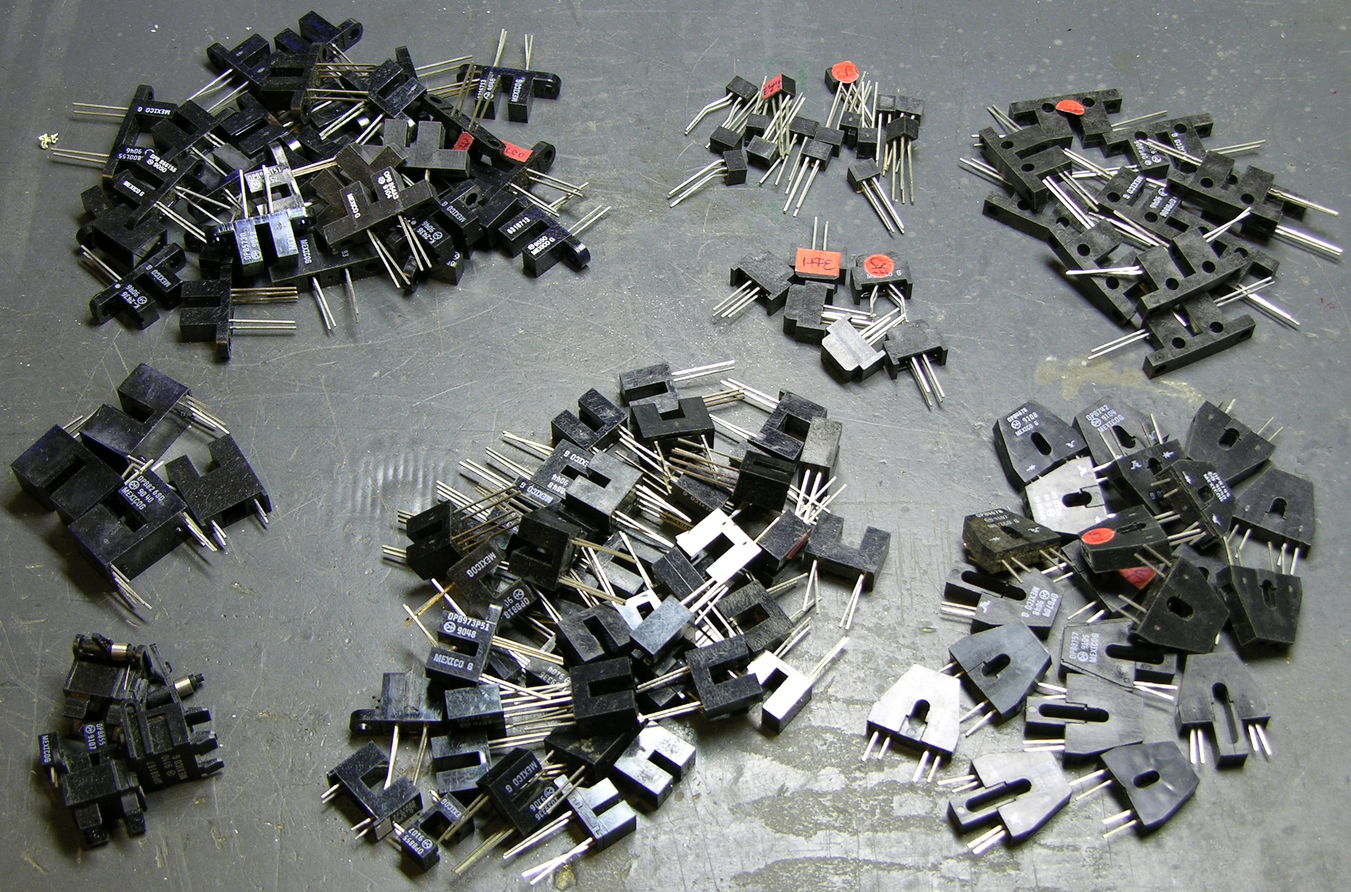
And none of them worked for me. All of them that I tested had a resistance of about 10-100MΩ through the phototransistor, with very little variation between lit and unlit conditions. [See comments for discussion and correction.] I already expected to have to use an op-amp to boost the signal; but on my scope I was seeing about as much 60Hz interference as signal, so I didn’t see much point in going further.
I figured surely I must have some other optoreflectors around the house, but I couldn’t find any. Failing that, maybe I could find a separate IR LED and phototransistor to make a giant optointerruptor? My friend Joel reminded me that I had some in my Boe-Bot, but their receivers turned out to require a modulated 38kHz signal, and I didn’t want to mess with it. I had an ancient IR LED / phototransistor pair from Radio Shack, but (according to my IR detector card) the LED was burned out. (I didn’t know they were still carried, and I should simply have picked up another pair, but it was late in the evening and the store closed. I’ll get myself another pair to play with later.)
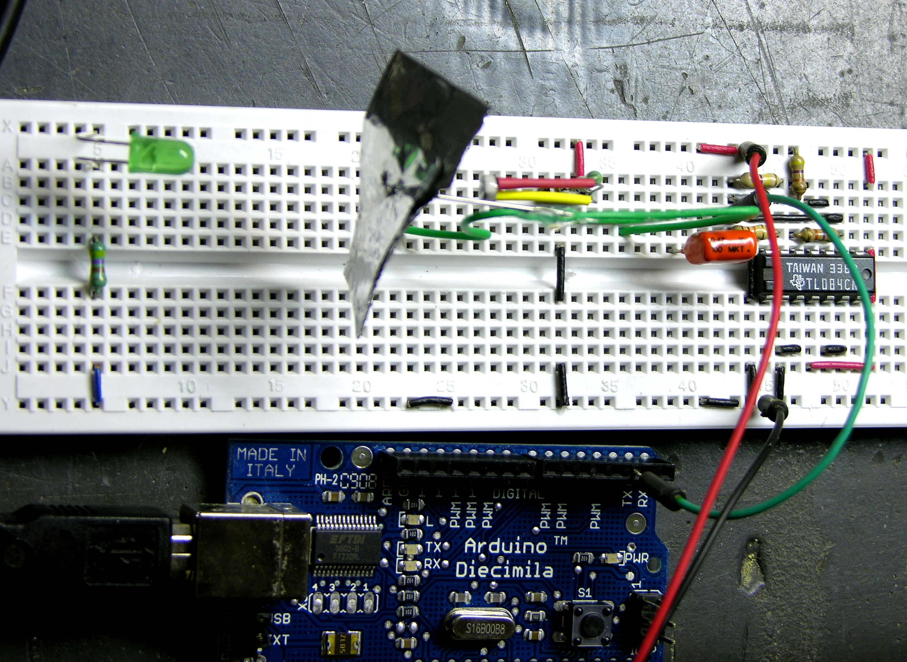
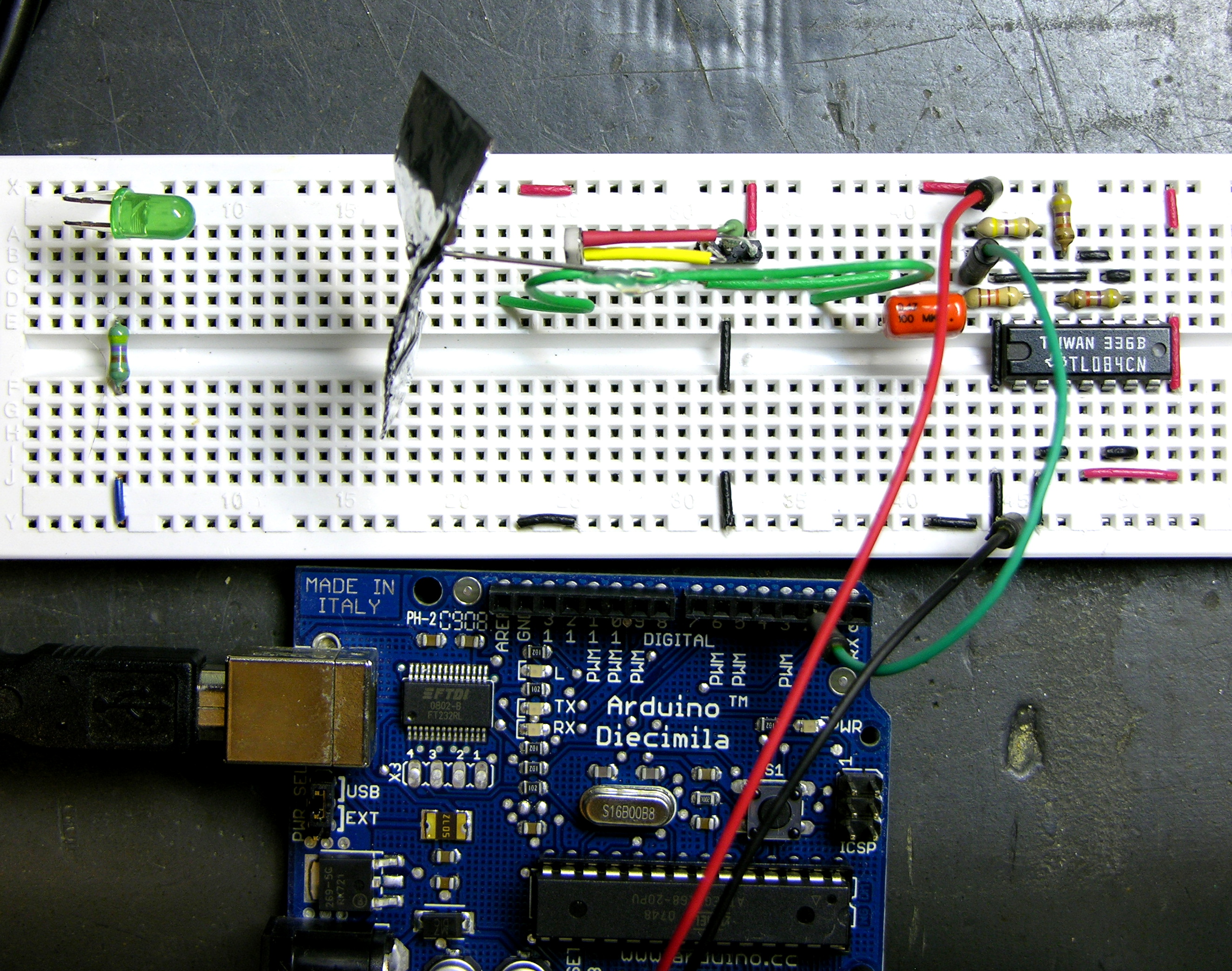
I really wanted to get this thing going, so I grabbed a CdS photocell and a green LED. The photocell (with the red and yellow heatshrink in the upper center of the picture below) was already soldered to a three-pin header with a matching resistor for a demo I had given, so I plugged it into a breadboard, bent it over, and aimed it at the LED. I made a propeller mount from a piece of wire and hot glue, and voila! One ugly optointerruptor.
Amplification
That gave me a varying DC voltage with (if I recall correctly) about .1V peak-peak. I wanted to use a digital input on the Arduino rather than having to constantly read A/D conversion, so I needed to amplify the signal to as close to 0-5V swing as possible.
Noise I was seeing in the signal — probably variations in visible room lighting that the photocell was picking up, and which I might have been able to mask out by enclosing the whole board in heavy paper — made me nervous about using a comparator or running the op-amp at infinite gain; I feared I’d end up counting lots of twitches in ambient lighting conditions. I really wanted to have a smoothly varying analog signal as the propeller blade entered the light path, completely blocked the light, and exited, to use a Schmitt-trigger to digitize the signal (more on that in part 2).
I used one op-amp of a TL084 (low-voltage op-amp, so I could use it with my single +5V supply instead of the usual ± supply) in a capacitor-coupled, inverting configuration to boost the signal. I found experimentally that a gain of about 40 gave me a good, consistent read of the LED without being overly sensitive to the random noise.
Next, digital connections and Arduino interrupt programming.
If you are still looking and want to scrounge something, I have found old VCRs usually have a few useful reflective sensing ir LED/sensor pairs in them.
Josh, I don’t need them right now but they’d be nice to have on hand. Do you recall where in the VCRs they’re used?
Hi Keith,
For future reference, those photointerruptors would probably be ok. Depending on your ohmmeter, they probably won’t show any resistance change. As they’re transistors they need a bias voltage applied between the collector and emitter. In a normal bipolar transistor the current that flows from collector to emitter is controlled by the current flowing from base to emitter. In a phototransistor the base current is created by incident light.
So connect the emitter to ground, and the collector to your power rail via a bias resistor. The voltage on the collector is your output signal. Depends on your device, but you probably want a collector current around 1mA. The voltage across the transistor will be between 1 and 2V, so with, say, a 5V supply the bias resistor will be around 3-4k. Check the datasheets for some more accurate numbers, and experiment with values to tune the sensitivity. A very similar circuit may be used for a photodiode; just make sure it’s reverse-biased.
Your ohmmeter probably only puts tens of mV across the transistor, so it’s nowhere near conducting and measures high resistance. Even if it did put a couple of volts across the transistor, without knowing the circuitry of the ohmmeter the results won’t help you design a circuit.
Good luck,
Jeff
Jeff, thanks for challenging me on my sloppy prototyping, sloppy thinking, and sloppy description. The curse and blessing of keeping a blog is exposing my mistakes for all the world to see and correct.
I was actually testing the optoreflector in circuit and estimating “resistance” based on the value of the series resistor on the collector. However, I think I tried some resistors that I had misfiled and was grabbing things too fast to double-check their values, so I wasn’t using what I thought I was using, which led me far astray.
Further, I hadn’t looked for a datasheet and assumed the optoreflector would function at a distance of an inch. In fact, now that I’ve found a datasheet, I see the nominal distance is about .1″, which is far too short for my application, and further explains why I was getting ludicrous results in my testing.
So out of curiosity I just hooked the optoreflector back up and tested with a bunch of resistors. My bench power supply was producing 4.93V and RD was 220Ω. The phototransistor’s series resistor was on the collector (not emitter), hence RC.
You can see that the best bang for the buck comes around 100KΩ — a large enough voltage swing that I’d be comfortable feeding that into a Schmitt-trigger input with no amplification or buffering (assuming the input impedance was high enough, which I think it is).
Of course there’s still the problem that it’s optimized to work at .1″ and really doesn’t work at all at the 1″ that I needed for this application. But I’m very glad to know how to use these right, for future reference.
Thanks again!
Nice results; that’s a pretty good voltage swing. Sounds like I underestimated your level of understanding, sorry!