Ultrasonic rangefinders detect objects and measure distance the same way as a bat: Emit a high-pitched “ping” and measure how long it takes the echo to return. The speed of sound in air is nearly constant (ignoring slight variations due to air pressure and humidity), so the time from ping to echo translates directly into the distance to the object.
I’m interested in ultrasonic rangefinders for both hobby robotics and our TechArt final project. They’re available commercially, but $25 each adds up pretty fast if you need multiples to establish a view all around a bot or across the wide front of an art installation. All Electronics has transducer elements for $1 each in quantities of 10 or more, so I ordered a batch of them in hopes of building a rangefinder myself. At $2 each (two transducers, for send and receive), I can add a fair bit of supporting circuitry before hitting the $25 mark.
The Plan
I’m basing my circuit on a design by Gerald Coe at http://www.robot-electronics.co.uk/htm/srf1.shtml, and adapting it for different design goals. His circuit uses a dedicated PIC to provide the oscillator, a MAX232 to generate 16V to drive the transmitter, and 40kHz transducers. For now, I want to run my rangefinder from an existing LogoChip that’s also doing other work, avoid the complexities the MAX232 adds, and use transducers with a different nominal frequency. Later, I might build separate modules intended to stand alone and run with very low power.
Initial Testing
According to a comment on the All Electronics page for the transducers I ordered, they run at 24kHz. The first order of business was confirming that operating frequency.
I hooked my function generator to my frequency counter and scope and dialed in 24kHz, to make sure I was in the neighborhood before connecting the transducer. I then connected one transducer to the function generator to serve as the transmitter (with the frequency counter still attached), and the other transducer to the scope to serve as the receiver.
When I pointed the transmitter at the receiver, a signal showed up on the scope; when I pointed it away, the signal abated. I could bounce it off my hand and receive it, but not off the ceiling. (I’m guessing the elements weren’t aimed well enough and/or the amplitude wasn’t high enough.) And changing the oscillator frequency confirmed that 24kHz is indeed optimal.
So the project is at least possible. That’s a good start!
Connecting the LogoChip
I really didn’t feel like disassembling my balance-bot project, so I’m sure glad I bought several PICs! I built up a breadboard with another LogoChip on it and verified operation. Then I took my motor-control PWM code and cleaned it up to generate a single frequency signal.
Testing with my frequency counter and scope hooked up, it looks like I need timer 2 with a prescalar of 1 and a period of 82 to get as close as possible to 24kHz. Hm, 82 * 24k ≅ 2M, which tells me that I really don’t understand what timer 2 is using for an input clock. Wait–yes, I got it. The PIC has an internal 4x increase in oscillator speed, so the 2Mhz timer oscillator leads to the 10Mhz clocking.
Driving the Transmitter
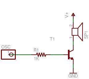
I first tried powering the transmitter element with an NPN driver, for simplicity and to allow experimentation with the drive voltage:
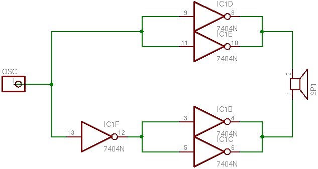
I connected the receiver element to my scope to detect the signal, and was surprised to detect nothing. I looked back at Coe’s schematic and noticed that he drives his transmitter in a push-pull arrangement using the MAX232, so I scrounged around for something with totem-pole outputs that I could use to test. The quickest thing I could come up with was a 7404:
And this time, I did show a received signal on the scope, albeit a slightly weak one; so I guess the push-pull drive is necessary.
I’m not satisfied being restricted to a 5V drive, because Coe specifically mentions using 16V to get adequate detection at greater range. However, I’m not sure I have anything on hand that will do exactly the right job and which I’m happy using. None of the options quite work out:
- The 74xx chips with “high-power output” and 754xx peripheral drivers run open-collector, and I don’t see a good way to use that to provide push-pull.
- The 754410 H-bridge driver adds about $2 to the cost–not bad, but I’d rather avoid it if I could.
- The MAX232 adds about $1 plus numerous supporting components–and Coe mentioned that it generates enough noise that he shut it down after each ping to keep it from interfering with the echo detection circuitry.
I’ll probably prototype with the 754410 since I have some on hand, and keep looking for other options.
hey, interesting project i would like to create a ultrasonic scanner to bone and muscles, do you have any idea where to find diy projects, and ideas for this project?
wish you the best from michael
Sorry, Michael, I have no experience with ultrasound scanning.
hey micheal..even i am making a project using ultasonic sensors facing the same problam of cost..
well can u tell me are these similar to SRF05
Hi, driving of piezo using simple NPN driver is also possible, you just have to add resistor in parralel with piezo to charge it while NPN is not conducting. Lower pad was still discharged. After that, you will transmit a wave.
hope it helps
Pavel
Hi
i too want to build a cheap range finder, i have a piezo with a cone built into it, it’s from one of those ultrasonic pest control devices (i didn’t notice it having any effect on bugs, i could just barely hear it so it ended up anoying me instead)…
why do all units have two transducers??? my idea is to hook it up to a PIC with a resistor in parallel like pavel says. one wire to PWM and the other to ADC.
1) make ADC pin into output ground.
2) 40khz on PWM for… 50ms?
3)make PWM pin into output ground, turn ADC pin into ADC input
4)wait for noise to go away, then wait for echo.
why would this not work?? i only need like 20cm range, so pwm out should be enough, also, i know the amplitude i can expect for the echo and it’s length, that way filter out other noise… i’m surprised not to find projects like this alreaddy on the internet, can anyone tell me why?
Ryan, some of the newer ones have a single transducer. But the reason to have two is that the transmitting transducer tends to ring (you’re driving it at its resonant frequency) for quite a while after you stop the drive signal — long enough to make it impossible to detect an echo coming back from a near object.
i imagine the transmitter rings for a long time because the transistor remains open, while the piezo (practicaly a capacitor) froms a tank circuit with the inductor… in the single transducer scenario both pins of the piezo are grounded, that should kill the oscilation immediatly… as for mechanical vibration in the PCB, mounting brackets etc… that’s probably the same for both single and dual transducer rangers… and just have to wait for the noise to die down… dual transduceers make sense when you want long range, one with dedicated tank circuit the other with an amp… but for short distances i see no advantage in using two… and costs more
hi
I’m electronic student
can u help me ?~!!!!!!!!
i want to make a rangefinder which have sense a Accuracy 1mm
(& it will ranges distance of a liquids)
please help me
tank u
Shad’mehr, is this for a class assignment?
Hello Keith,
me i try to build an ultrasonic range finder but with an tranducer. This transducer must send and receive the pulses. But I’m not able to receive the pulses.. if i use 2 tranducers (one as emitter and an other one as receiver) there is no pbl! Have u an circuit or schema or something else to find my error and to understand better on how i have to this circuit?
My transdcuer works with 12v, and my microcontroller gives only 3.3v so.. i use one NPN to invert the PWM and to obtain a PWM with 12v.. and afeter i use a PNP to invert again the signal. With this solution i don’t polarize the transducer all the time.. In simulation it’s work.. when i use each stage separatly it’s works perfectly too.. but combined not!
Thank u for u answer
It’s for an personnal project
Lolo, I’m sorry but I really don’t know quite what’s going wrong with your transducer. One thing that comes to mind is that a transducer will “ring” (vibrate) for a while after sending a pulse, and the commercial single-transducer rangefinders have a “dead” period after sending the pulse before they listen for the echo, but it sounds like you may be doing that already.
exactly, i see this ring, but i don’t see the echo. it’s possible to send u my circuit(schema) per mail, if u see it, perhaps u can see something.. or not. But il really don’t know what i can do to solve this problem :s
Lolo, I don’t think I’m likely to be able to see what’s wrong with your rangefinder from the circuit alone — I expect I’d probably have to play with it for a while with a scope watching things at different places in the circuit. Even if you felt like sending it to me, I’m afraid I really don’t have time to take that on right now.
You said you had it working with two transducers — why not use it that way?
hi
I’m using the same concept for my range project
but when i tried to simulate it using Multisim v11.0
it won’t simulate “giving me an error without knowing where the error is”
the photo for my circuit is below
http://a.domaindlx.com/lio2000/Images/transmitter.JPG
I hope it works
if the pic didn’t open keep refreshing
is everything right their
it is my graduation project and I’m on deadline here