I’ve been plugging away at the CupCake “Plastruder” in the evenings, and I now have the mechanical assembly mostly finished, pending the arrival of some custom parts.
I’m delighted by the clear plexiglas design. And having the mechanical assembly — particularly the extruder — put together really highlights how small this thing is. That’s not a bad thing — for a given build capacity, the smaller the machine is, the better.
Support Assembly
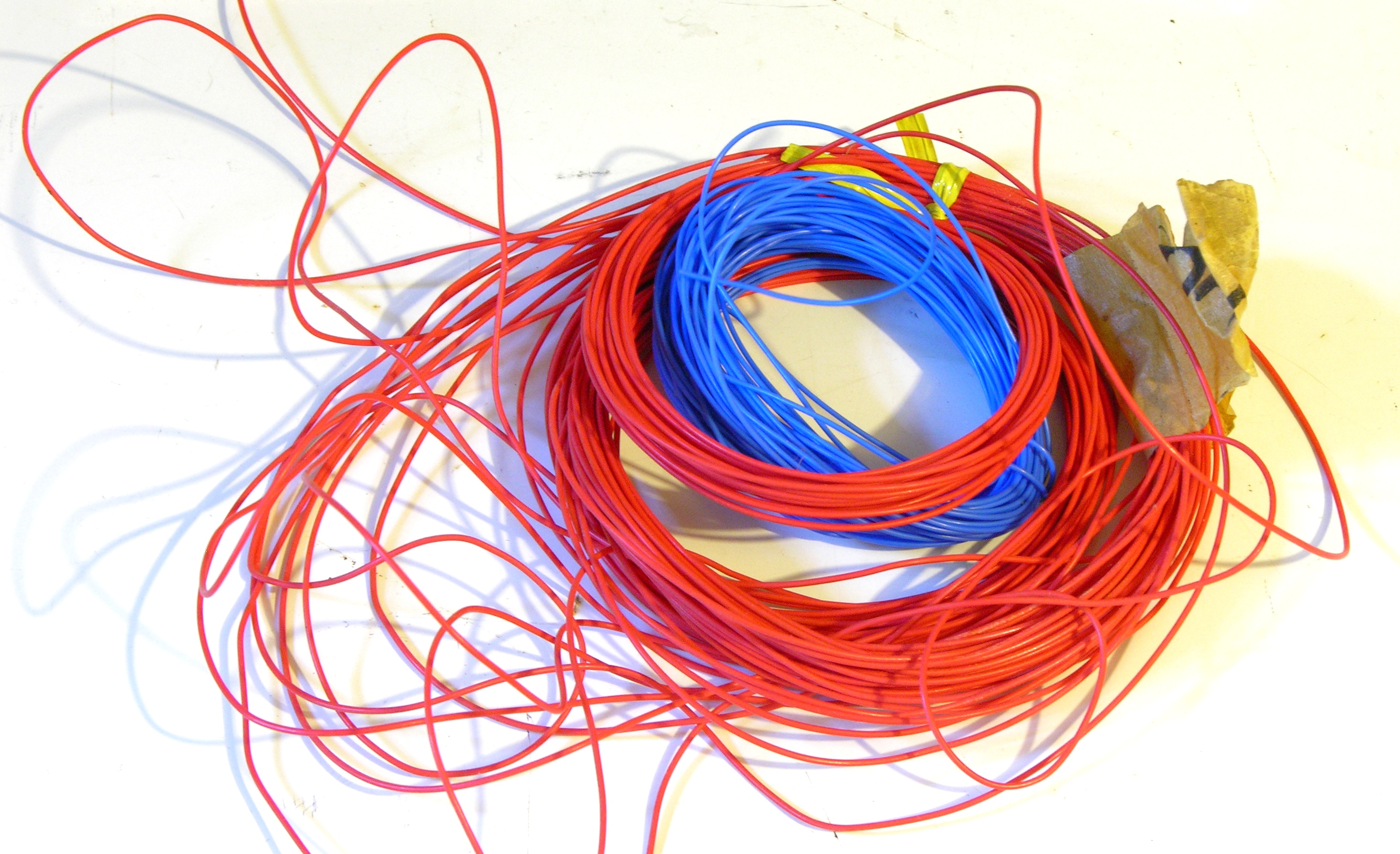
The extruder parts arrived as a bag of plexiglas pieces with their protective plastic coating on and a couple of bags of mechanical parts. Before using each piece, the blue plastic has to be peeled off.

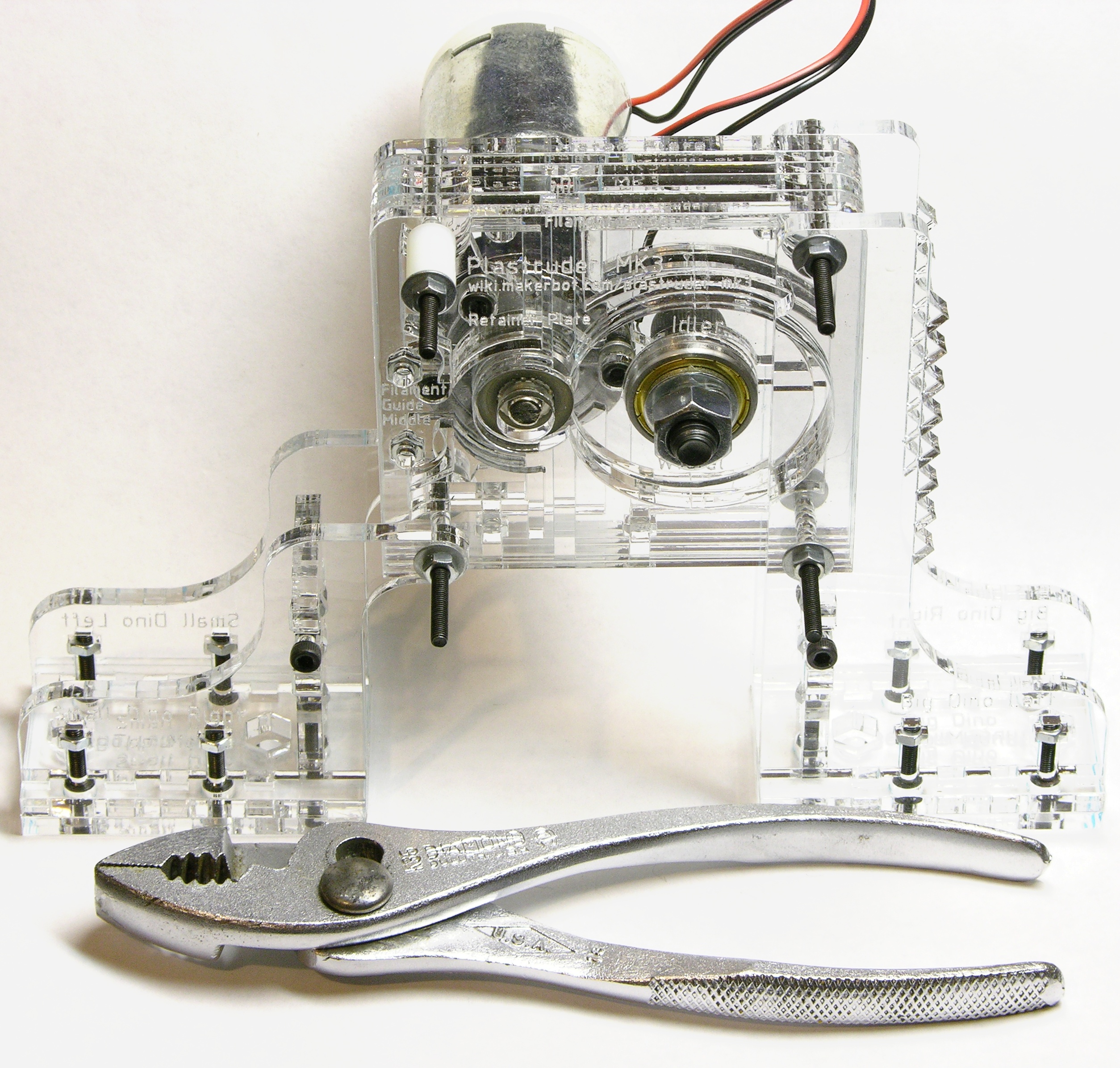
There’s room in the CupCake for a bit of whimsy — the vertical supports that hold up the edges of the filament feed are shaped like and referred to as dinosaurs. Very cute.
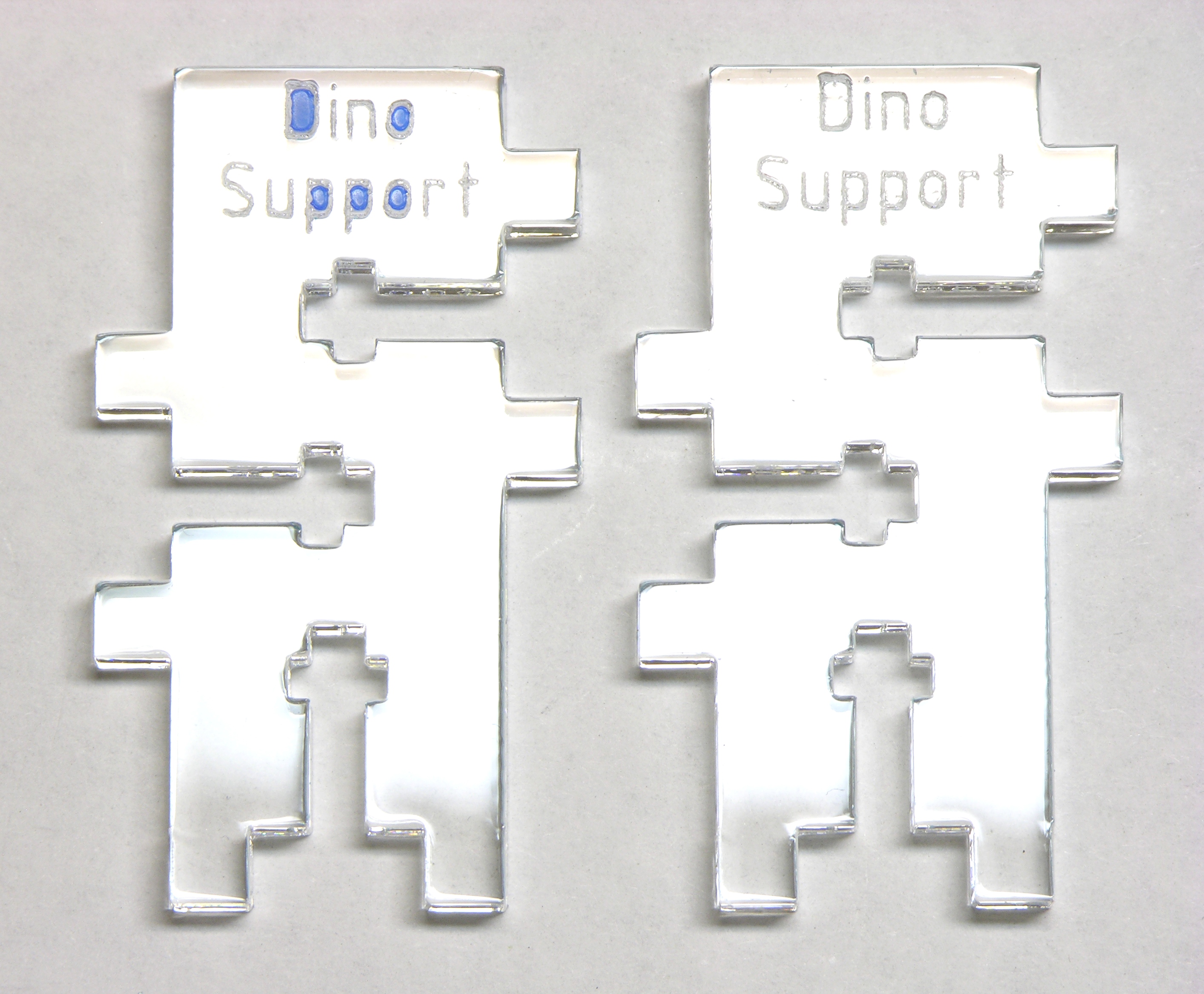
It was a pain getting all the tiny blue plastic pieces off the inside of the laser-etched letters — but totally worth it.
Superglue
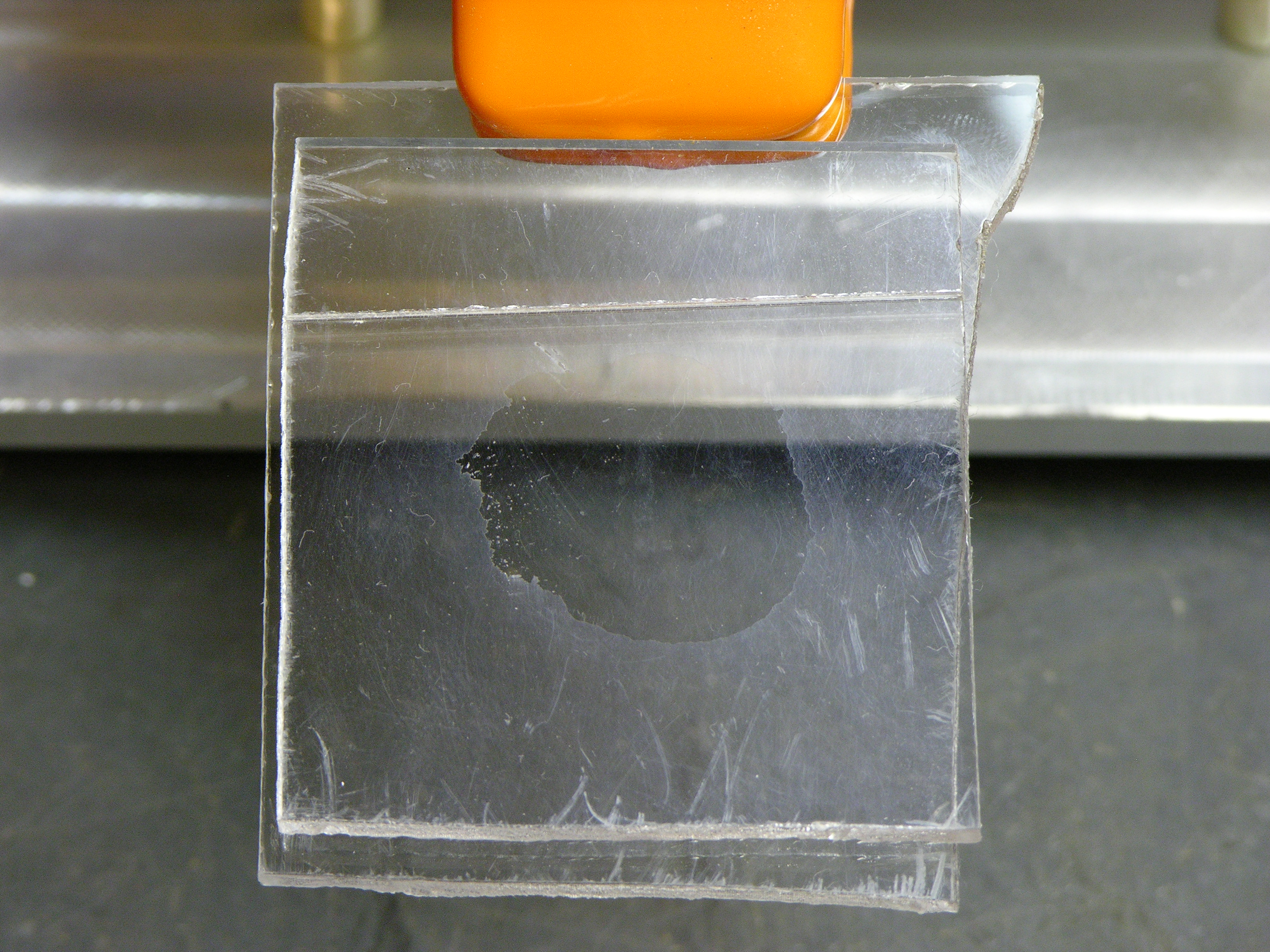
The left and right “dino” bases are made of two layers of plexi laminated together with superglue. I hadn’t face-glued plexiglas before, so I was curious how visible the glue joint would be and made a test patch with some scrap first. Interestingly enough, the glued area turns out to be clearer than the surrounding area — I think the glue filled in some of the scuff marks on the old stuff I was using.

Regardless, it did suggest to me that the glue marks would be somewhat visible, so I carefully daubed the glue in areas that would be hidden under the edge of a perpendicular piece, then clamped them for half an hour.
After removing the clamps, the glued pieces slid right apart, in contrast to my test pieces that I don’t think I could separate without shattering the plastic and gouging myself. My friend Mike Smith suggested the best explanation I’ve heard yet — the new plexi may have had a release agent on it, which I cleaned off the old pieces when I washed them to get the dust off.
Ideally I would have taken the pieces apart, cleaned them, and tried again. However, I’m a fraidy cat around superglue and wasn’t sure how to clean the (still wet) glue off the pieces so I could go wash them without somehow sticking them to myself in the process.
Instead, I clamped them overnight; and by morning, they seemed secure. I speculate that in the moving and sliding around, the liquid glue cleaned away enough of the release agent (or dissolved it more evenly throughout the glue instead of forming a barrier between the glue and plastic) that it was able to hold well.
Lesson: Wash plastic with soap and water before gluing.
The instructions had actually said to assemble the supports first, then glue the second layer on afterward. That sounded trickier to me, so I had laminated the two pieces in advance.
Here’s a good reason not to do that: Tightening the screws caused stress marks in the plastic and/or glue that were much more visible than the glue marks I had been concerned about.
Lesson: To avoid stress marks, assemble and torque first; glue second.
Motor and Pulley
The CupCake uses a toothed pulley (made for toothed belts) to grip and feed the plastic filament into the heater assembly.
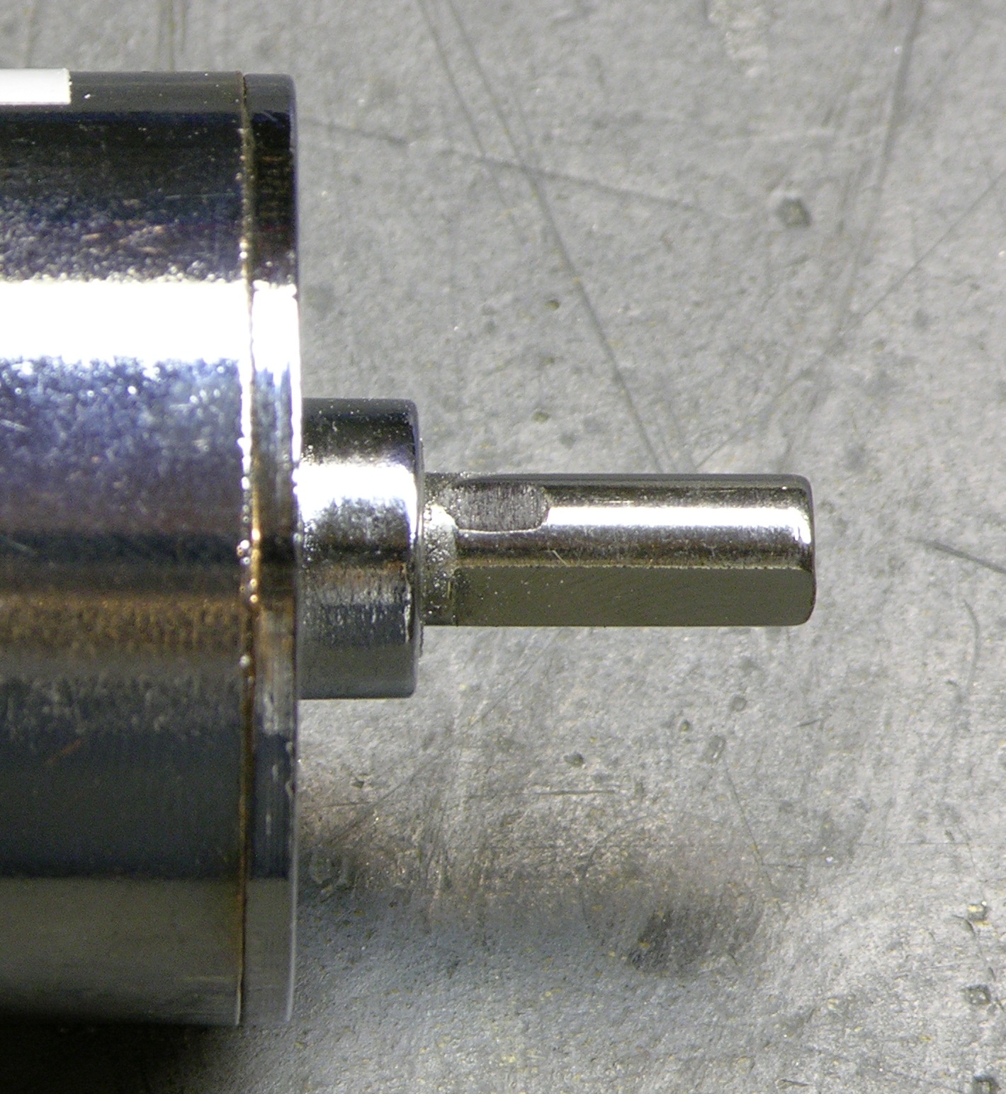
The pulley has two set screws at 90° and the assembly instructions say to tighten the proverbial daylights out of them — but the motor shipped with only a single-flat shaft. If I’m going to bother tightening daylights, at least I’m going to do it with a flat for each set screw; so I filed a second one at the appropriate place.
An unanticipated advantage of having the flat not extend to the end of the shaft is that the pulley can be loose-fit for final positioning yet still unable to fall off the shaft. Slick!
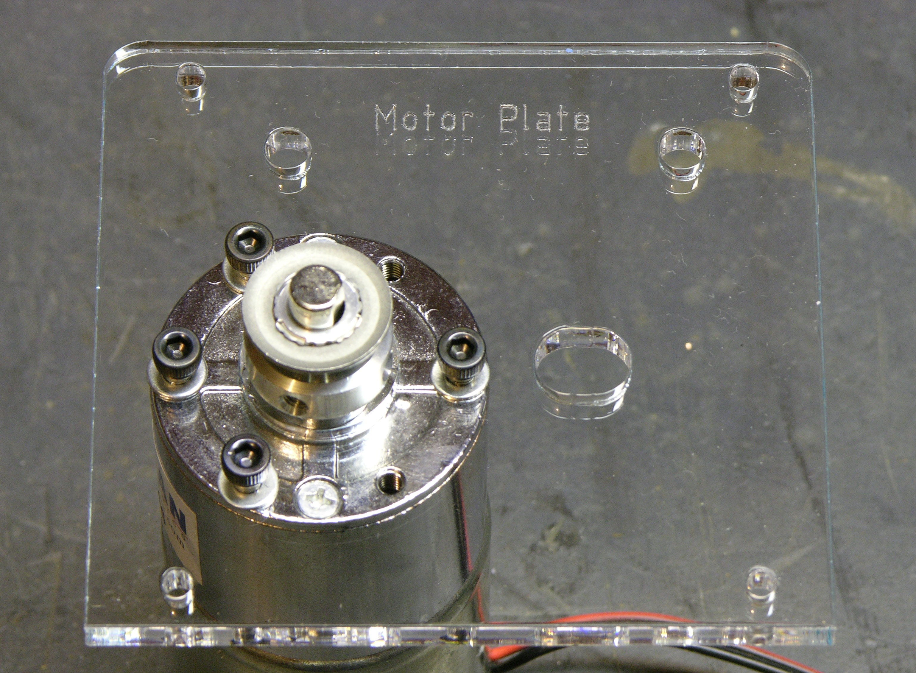
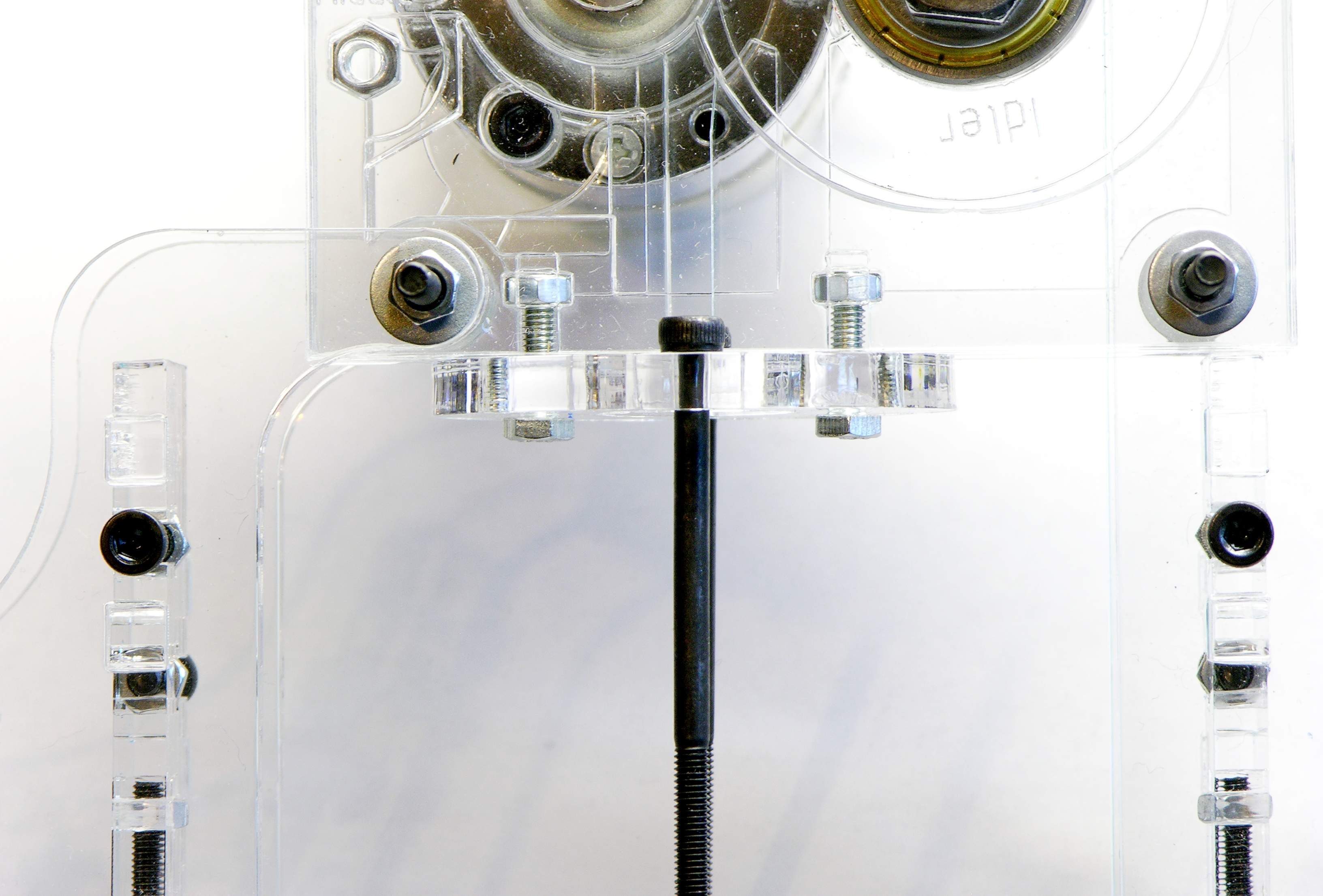
The filament feed assembly is made of layered plexiglas to mount the different parts and to provide a channel to feed the supply filament. The motor mounts to the first piece, and the others bolt together in a big sandwich.
I mounted the pulley as far onto the motor shaft as it would go; but the first time I assembled, the pulley still didn’t align properly with the filament channel. I took the assembly back apart and shimmed the whole motor a little further out with a layer of washers (these particular ones not included) between it and its mounting plate and it aligns now.
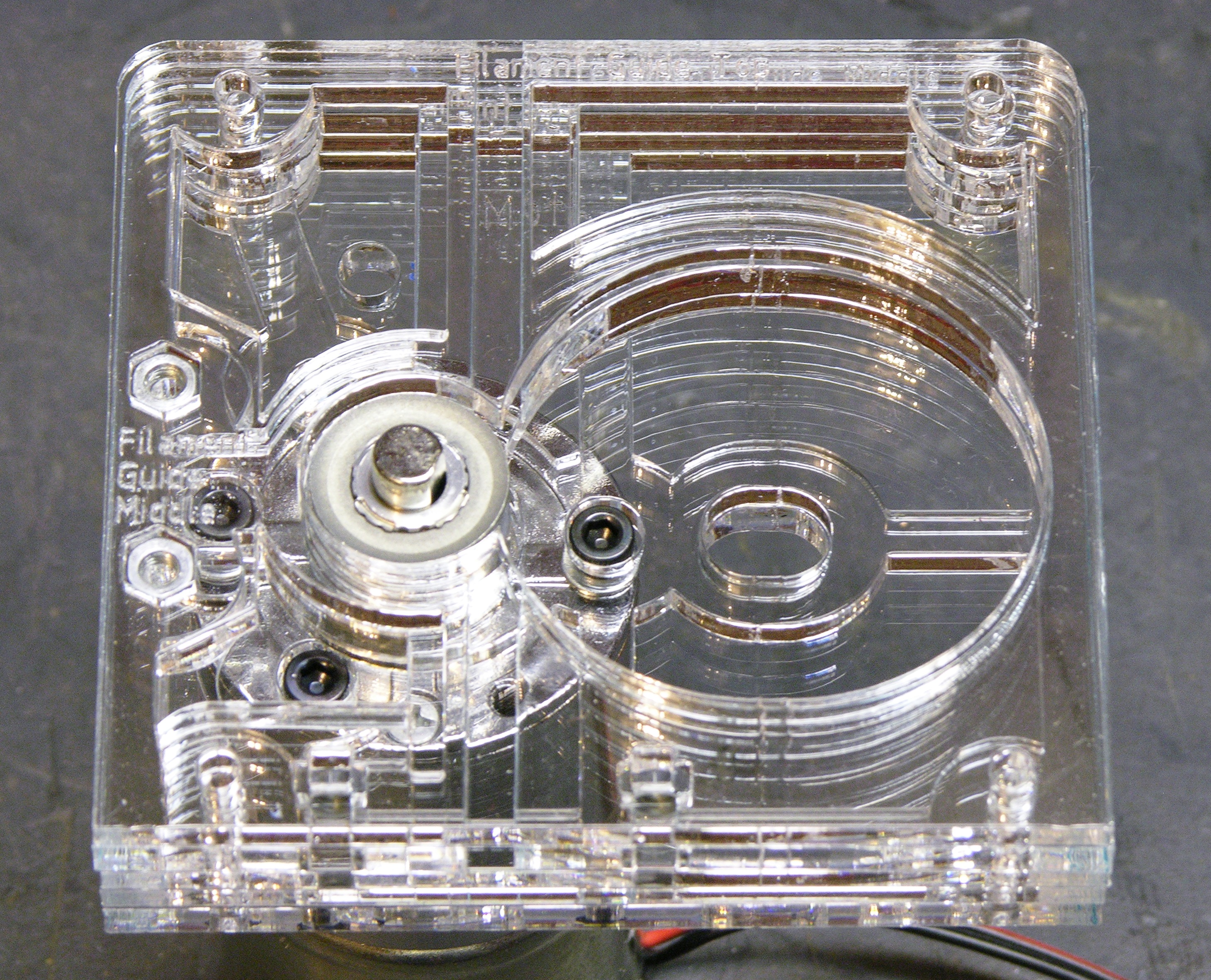
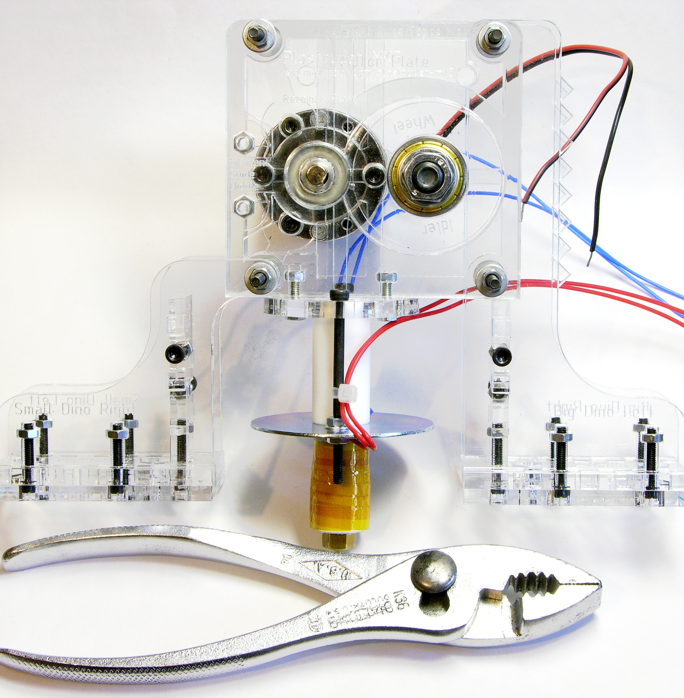
I love the crystalline, Fortress of Solitude (albeit not spiky) appearance of the filament feed. The idler wheel — also plexiglas and not shown here — goes in the recess at the right, and (after shimming the motor) perfectly mates with the filament drive pulley and the filament channel.
The completed filament feed, sans heater.
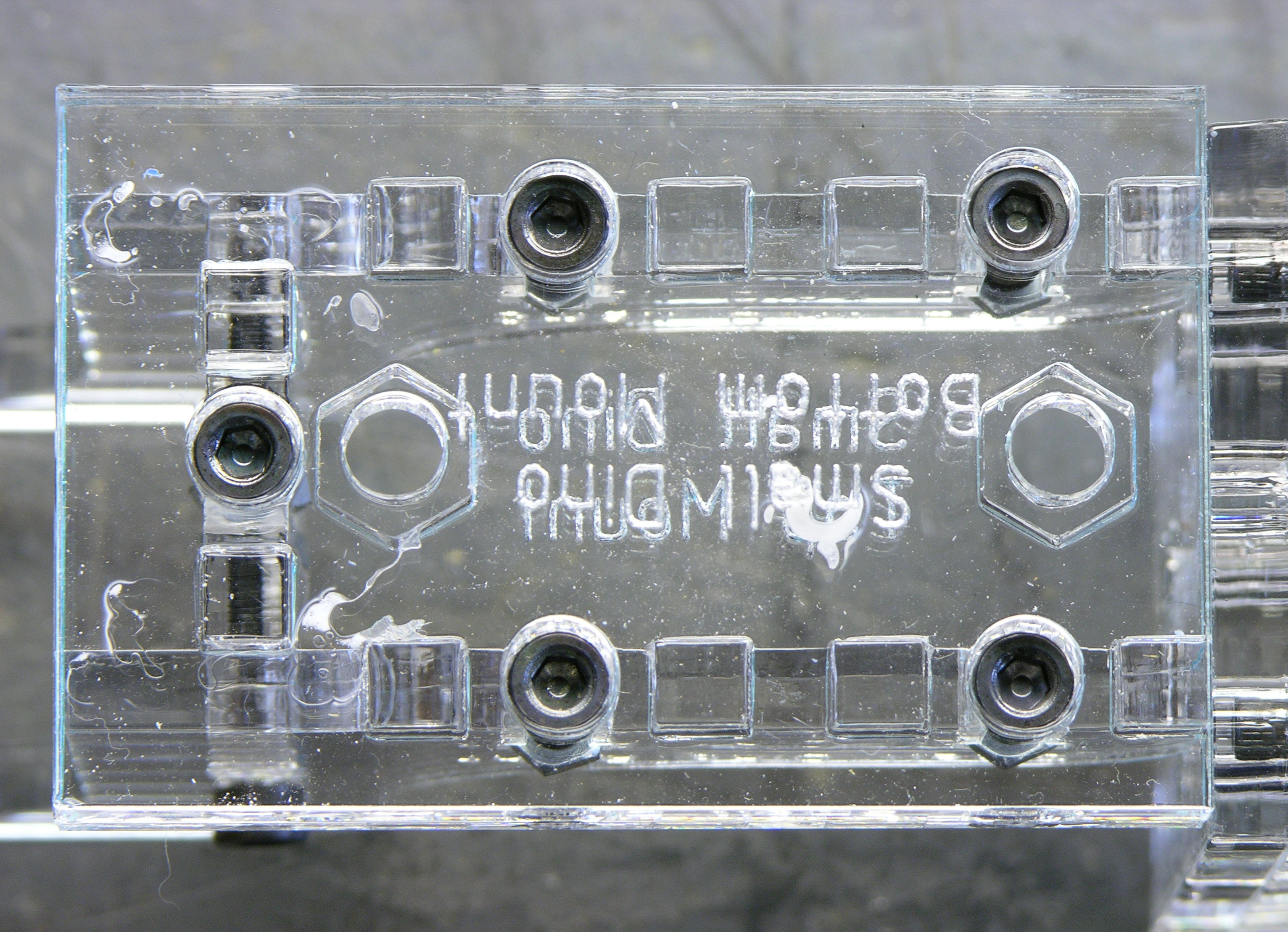
The white plastic spacer is on the upper left machine screw because only about half of the screw is threaded; and without the extra thickness of the dino head, the nut can’t thread far enough to grip the sandwich. In fact, the other three just barely don’t thread far enough, but it’s not as noticeable.
The controller board mounts on the front using the four screws. The assembly instructions suggest threading on more nuts as standoffs to clear the protruding idler axle, then mounting the board, then mounting more nuts to finish it off.
In the midst of all this glistening plastic, adding a stack of silver-colored nuts didn’t appeal to me. I contacted MakerBot to get a quote on laser-cutting me some washers of the same thickness as the dino heads, and they seem amenable and I’m waiting on my parts. This will enable me to
- Shim out the upper left plastic sandwich to the same thickness as the other three, so the white spacer isn’t needed and all four machine screws are even.
- Shim out all four machine screws past the last little bit of unthreaded shaft so the nuts hold the plastic sandwich together tightly.
- Build up a stack of clear plastic spacers as standoffs to mount the PC board, in my opinion more in keeping with the design of the rest of the device.
So for now, I’m leaving the PCB off until I can get my spacers.

Finally, it’s hard to see because everything is clear or white, but the center piece between the left dino front and back layers isn’t quite as wide as the thickness of the plastic sandwich, so there’s a bit of a gap (that only I would notice). Curiously, I think the center pieces are the same side on the left and right dinos, but the right dino doesn’t seem to have this problem.
Heater Assembly
The heater barrel is a DIY job, and the first step is cutting the nichrome to length (optimal resistance 6Ω; mine shipped at 8+Ω and required some trimming) and crimping on wire to feed from the controller to the heater.
The kit didn’t ship with wire, so I ran out to storage to grab some teflon-coated wire from Slim’s stash. I’d used teflon-insulated wire before while working on an avionics and test equipment assembly line and knew of its heat resistance. In quick tests, this wire’s insulation withstood a few seconds of flame without any noticeable deterioration and discolored after much longer than that. A good choice for connecting to a heating element.
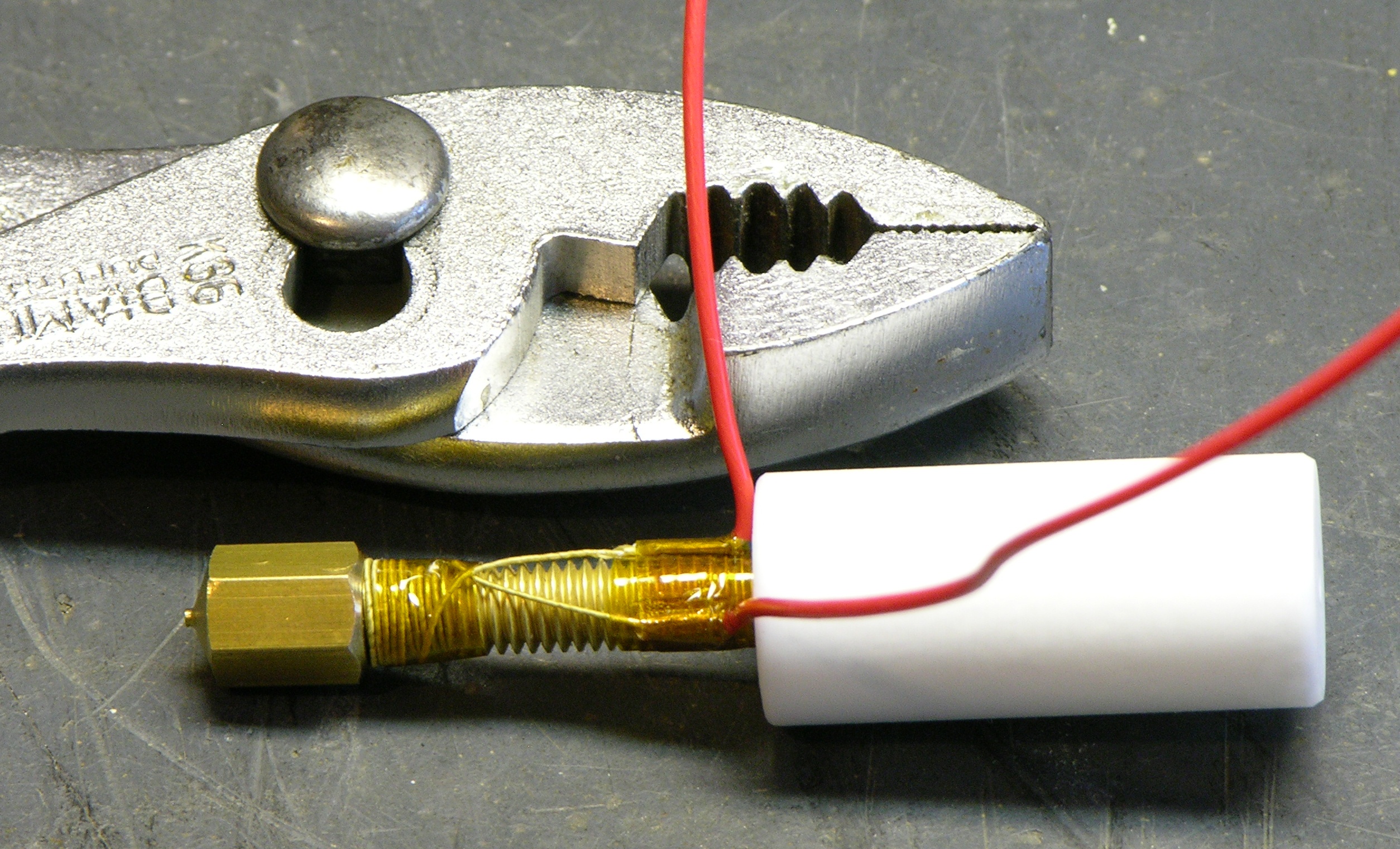
(Insulated) nichrome wire wound around the heater barrel; Kapton “space” tape holding everything in place.
Thermistor added to extrusion head and lots more space tape. The painters tape on the PTFE barrel is just holding the wires out of the way for convenience as I wrap.
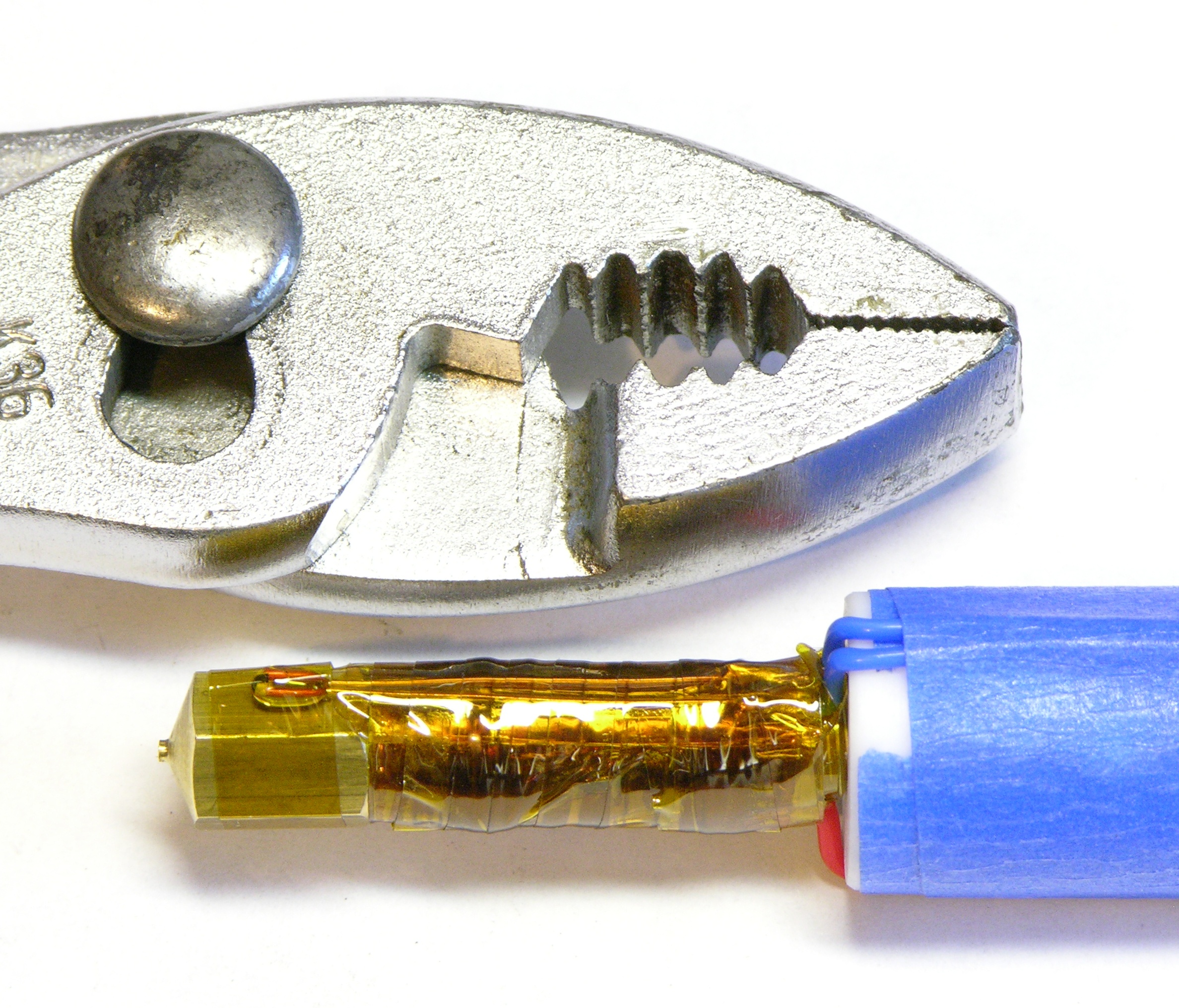
A note about this construction — it’s possible for the ABS to burn inside the nozzle, at which point it becomes impossible to get the ABS out of the nozzle by conventional means and you have to unscrew everything and soak it in acetone. (Thanks for posting all your exhaustive materials research, nophead!)
So I’m trying to keep the head as easy as possible to separate from the barrel, and I settled for one layer of tape around the thermister. Should be easy enough to undo and redo if it comes to that.
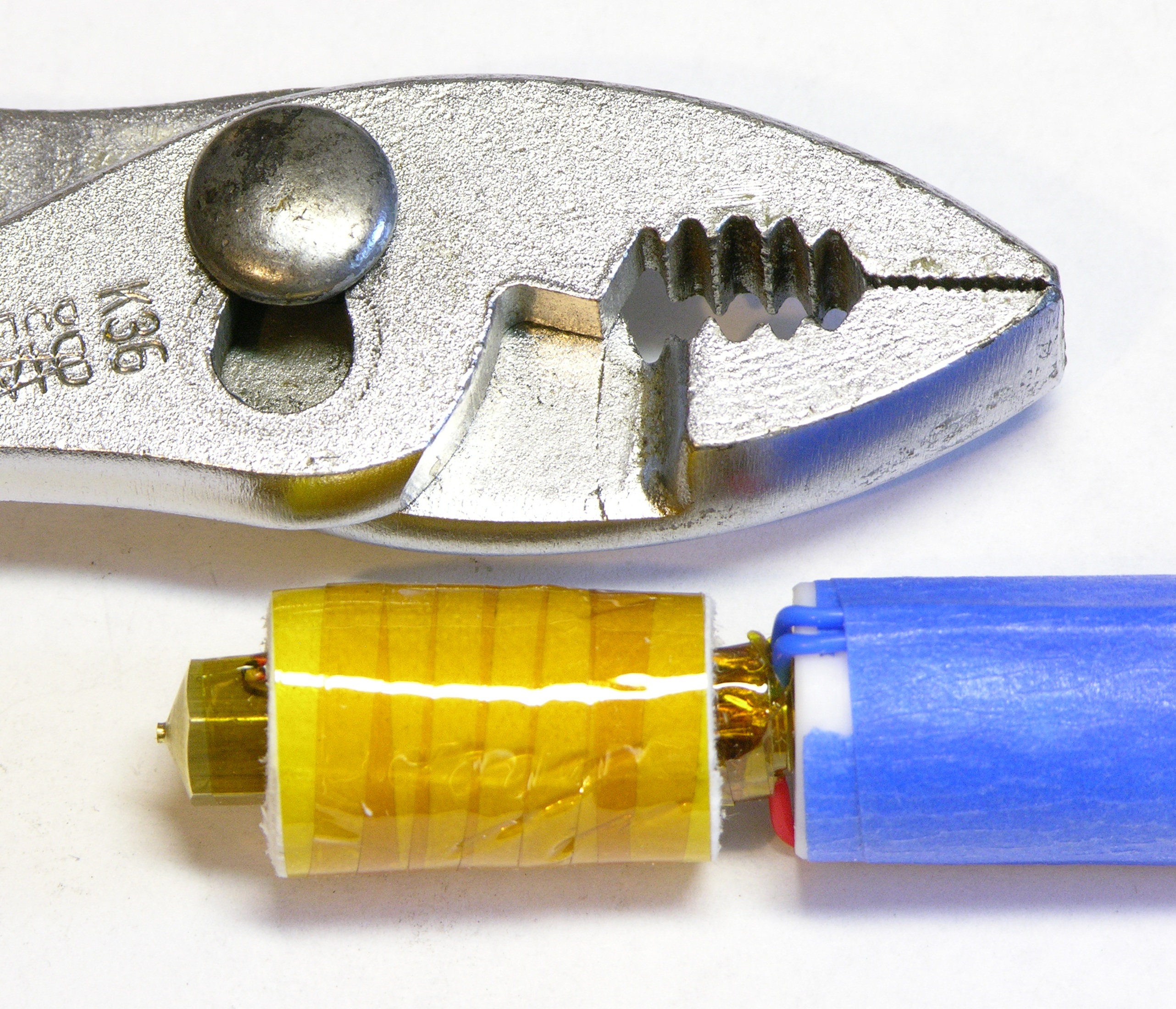
Insulated and ready to go.
Mounting the Heater
The heater barrel mounts to the filament drive via a mounting plate that bolts to the captive nuts in the plastic sandwich. Two of these things are not like the others; two of these things just do not belong.
The (black) 12mm M3 machine screws referenced in the assembly instructions are a bit too short to reach, and it looks like these two non-anodized screws were added as a last minute patch. No real harm done; and I’ll see if I can find some black hex-socket machine screws at the hardware store to replace them eventually.
Hm, anyone know where I can get black M3 washers???
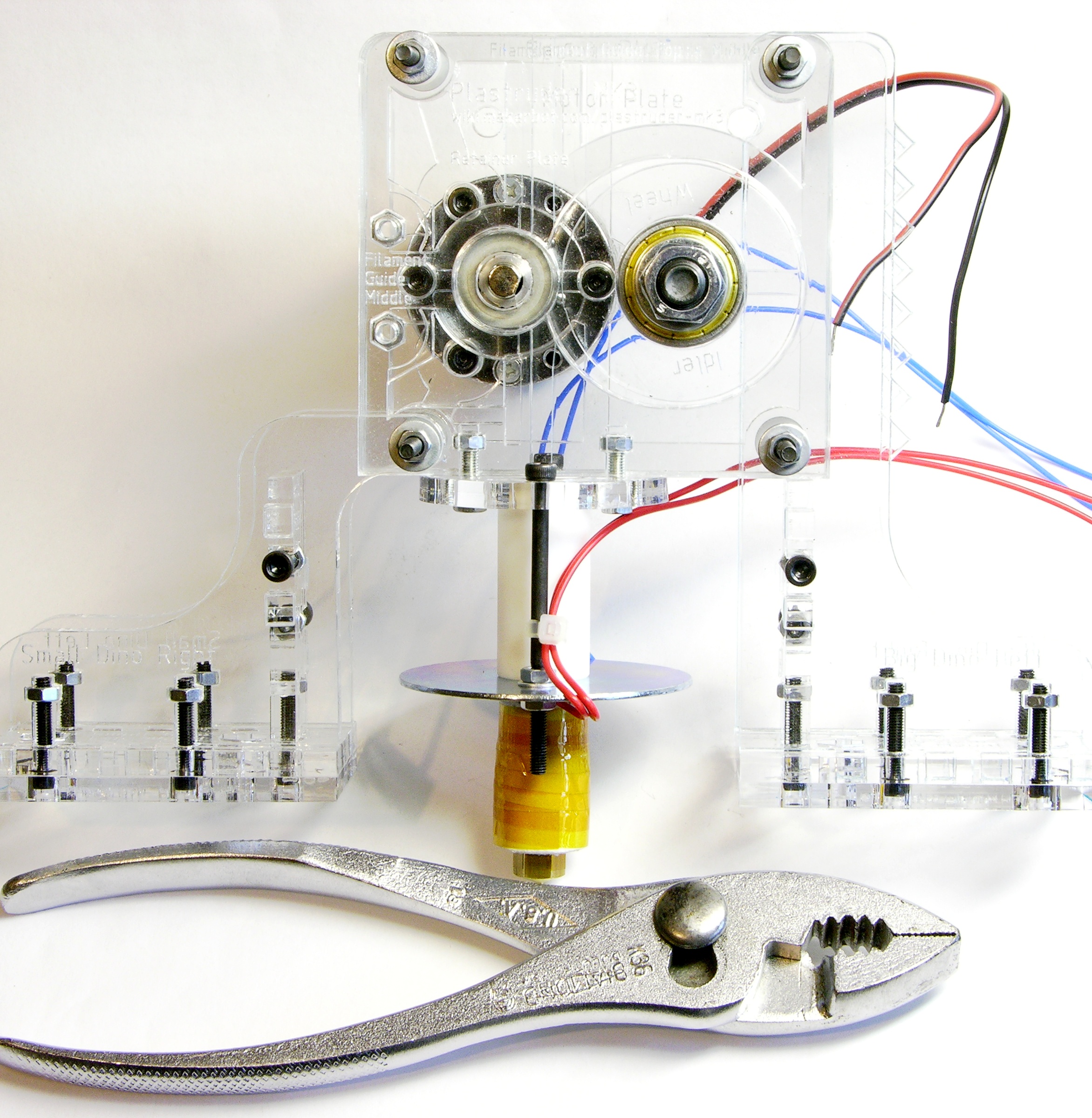
And there’s the whole assembly, minus the aforementioned controller PCB while I wait for my clear spacers.
Nice writeup Keith, and some good quality pictures.
Watch out for the width of the idler pulley slot though. The lasercutting is a little conservative, myself and a few others have had to file more away to get the extruder to work reliably.
Gav, thanks for the note! I’ll double-check the idler wheel spacing before I get going.