
Last Saturday I went shopping for lunch with a tape measure.
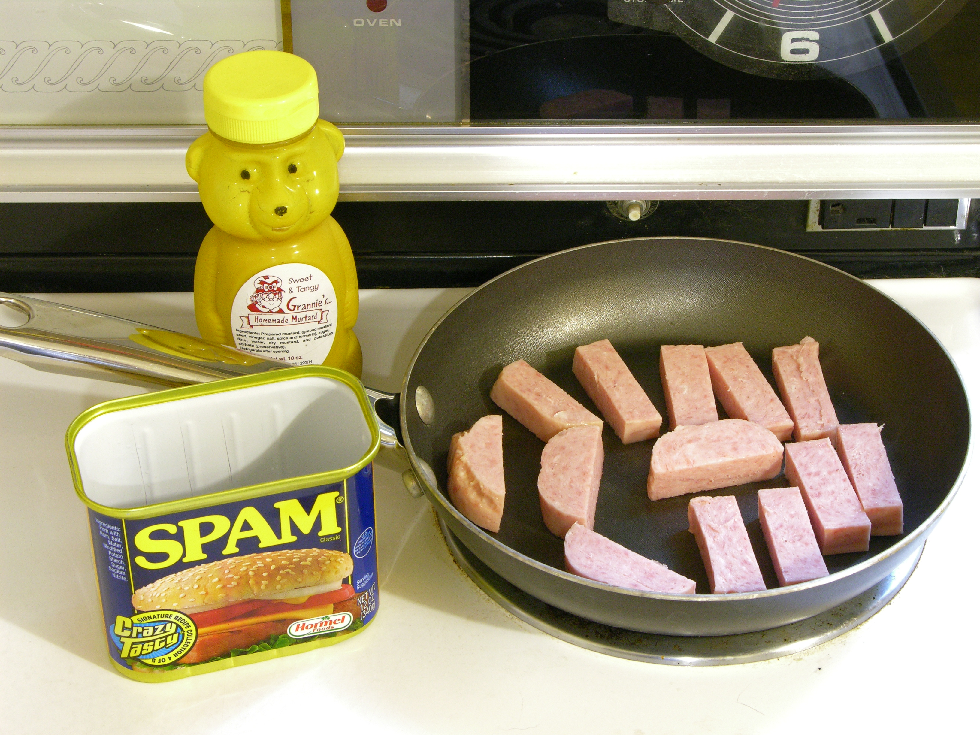
Delicious Spam™, fried up nice and crisp and served with Grannie’s “homemade” [what exactly does that word mean?] mustard. Yummmm!
The behavior of my CupCake during the first week of testing and parts-building had made me think that the nozzle was actually colder than the extruder controller believed it was — barely able to push plastic at allegedly 220°C and much happier at 230°C with not much scorching.

I had previously cross-referenced the extruder’s reported temperature with my infrared thermometer’s reading at room temperature (which I no longer trust) and had dipped the heated nozzle into a small pool of water to try to find the boiling point.
| Condition | Thermometer Measured | Thermometer Converted | Thermistor Reported |
|---|---|---|---|
| room temperature | 68°F | 20°C | 16°C |
| dipping nozzle into water and adjusting set temperature until water boils | 105°C |
In the 100-115°C range, the water would sizzle when the nozzle heater was on and stop boiling when it was off. It boiled most evenly between heating and cooling at a reported 105°C, so I was guessing that it thought 100°C was really 105°C.
This turned out to be incorrect; but it convinced me to perform a more proper thermal calibration, which is what counts.
Reference Temperatures
I believe I’m not the first to calibrate the RepRap / CupCake Plastruder temperature this way, but I haven’t seen detailed documentation on the procedure (nor have I tried particularly hard to find any).
The first step was establishing known reference temperatures at which to measure the thermistor’s resistance. Because I’ve come to suspect that my infrared thermometer is inaccurate — in some ranges, wildly so — the only reliable reference temperatures I had were the freezing and boiling points of water.
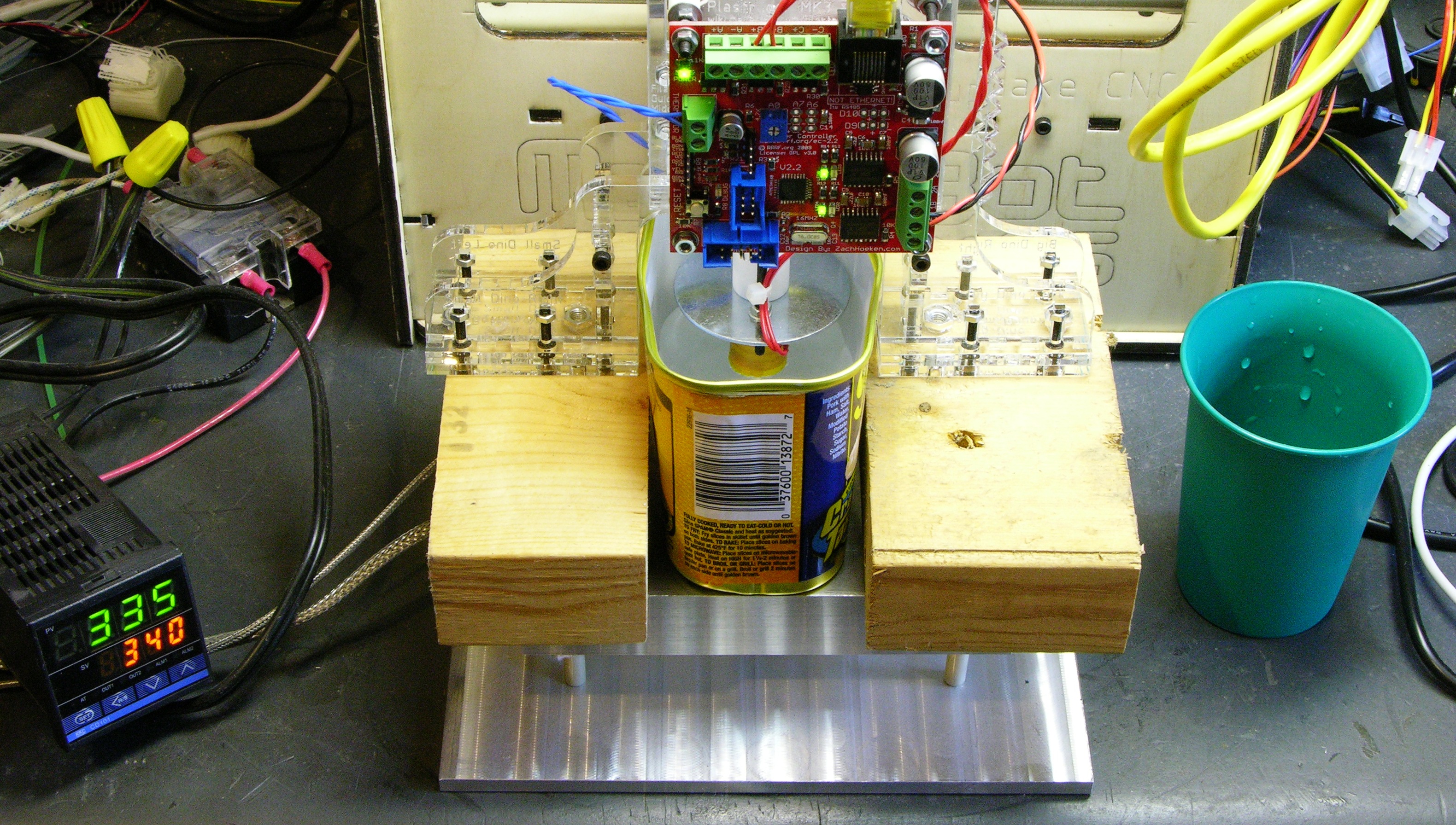
The Spam™ can was just the right size to fit between the support dinos and hold the water. (Yes, I went to the store specifically thinking I would buy Spam™ for the can. Yes, I really ate the Spam™. Yes, I really enjoyed it, although it was saltier than even I like.)
The PID-controlled hotplate is a red herring — its setpoint has nothing to do with the calibration. It’s just a handy way to heat water with relatively little risk of burning or melting my supports and in a convenient, controlled environment with no inquisitive feline assistance.
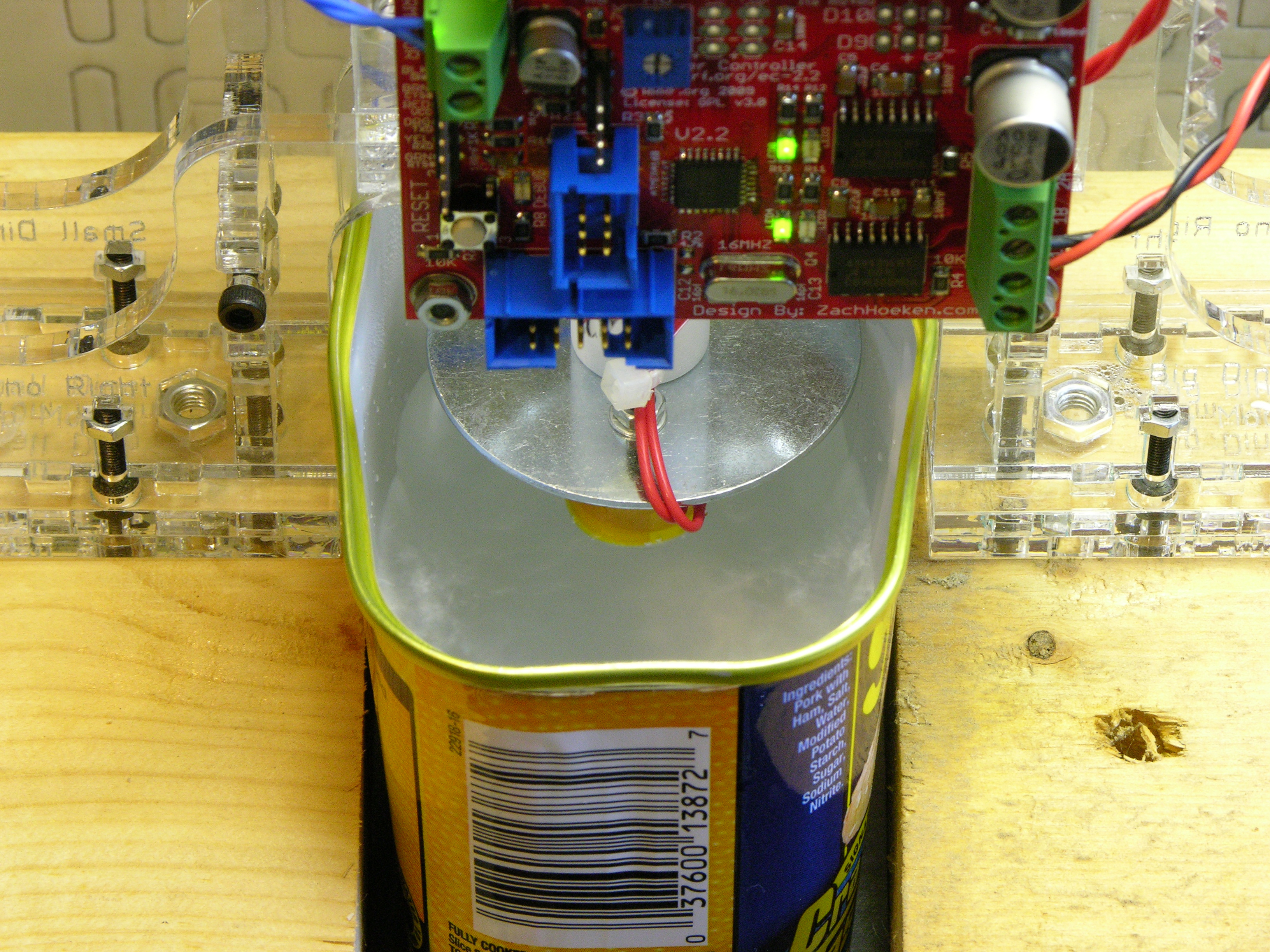
Tip: Mash the bottom of the can flat from the inside so there’s more surface area in contact with the heater. The first time I boiled this, it took forever.
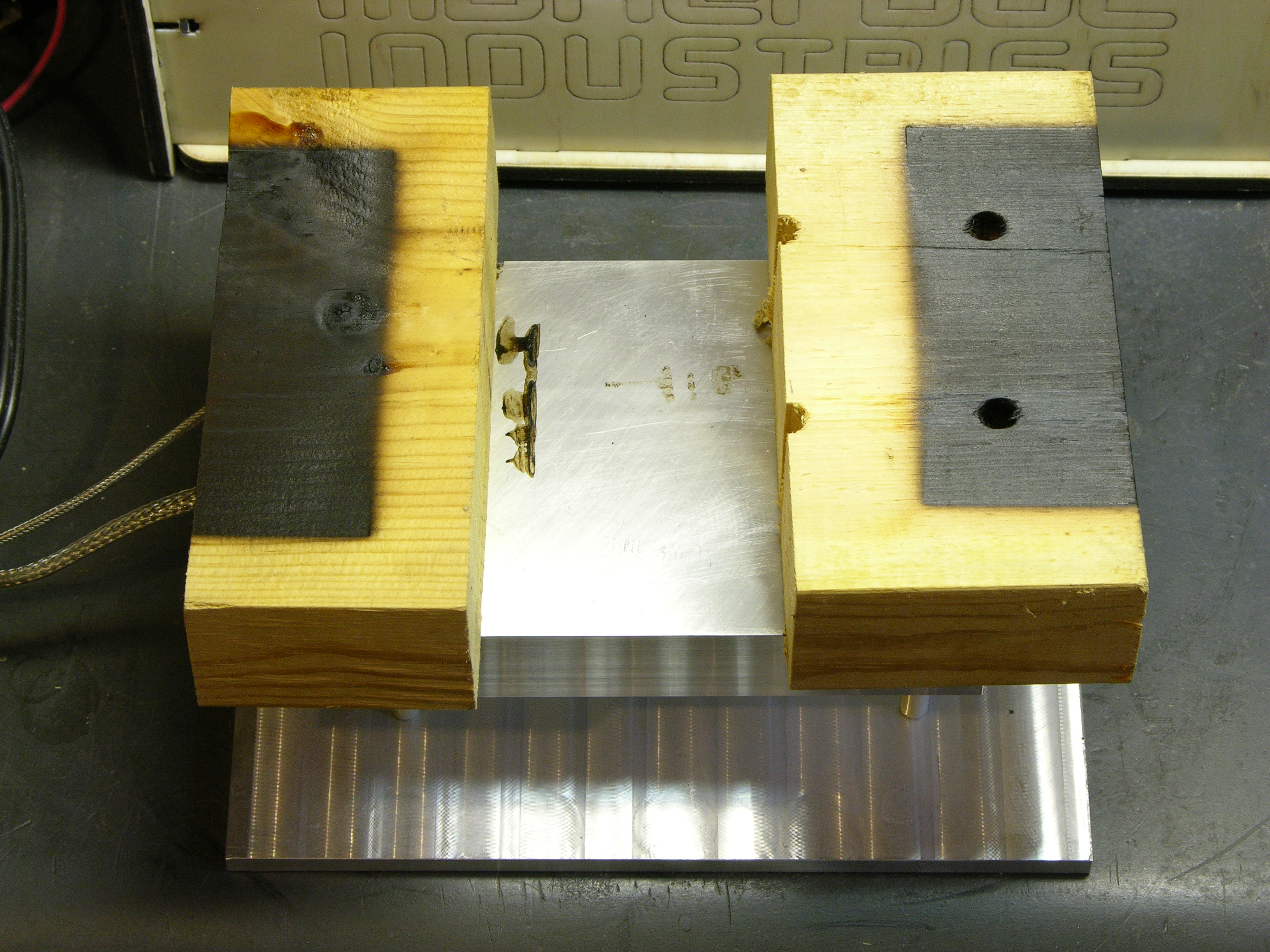
Tip: Pine, not so much the best choice for supports when I have to crank the hotplate temperature so high.
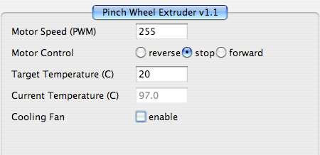
Although the measurement I needed was the resistance of the thermistor out of circuit, I was curious and let ReplicatorG take a reading at boiling also, just to confirm that I would really be making a difference. Seeing 97°C boiling was an affirmation that I should be able to improve things.
I put the Spam™ can in the freezer until a significant amount of the water was frozen, broke the surface ice, and repeated the measurements.
| Condition | Nominal Temperature | Reported Temperature | Thermistor Resistance |
|---|---|---|---|
| ice water | 0°C | 4°C | 268KΩ |
| boiling water at 1500′ elevation | 100°C | 97°C | 6.86KΩ |
I actually don’t know the boiling point at 1500′, and I understand it’s more dependent on barometric pressure than on raw altitude. Please some chemist, physicist, meteorologist, or politician with good truthiness tell me it won’t have made much difference.
The extruder was reporting 4°C at freezing and 97°C at boiling. I hoped I could improve these readings — especially since not only were the temperatures off but the scale of temperatures was off. It was reading only a 93°C difference between freezing and boiling whereas it should have read 100°C; so at ~220°C operating temperatures it might be reading a full 10°C low.
Note that this is the opposite of what I had suspected — I thought it was reading high. Regardless of whether my suspicion was right or wrong, I wanted an accurately calibrated temperature before starting to tune Skeinforge to my CupCake’s needs.
Also note that the thermistor reading must be taken out of circuit. The rest of the extruder board becomes parallel resistance via the power supply leads while it’s in-circuit (yes, with the power off) and the readings are orders of magnitude lower and useless. (Tip: Don’t waste time finding this out yourself, like I, uh, did.)
Calculating Thermistor Beta
Next I needed to calculate the thermistor’s beta, which nophead describes in detail as a simple model of the nonlinearity of the thermistor’s resistance as a function of temperature — essential to know in order to correct for the nonlinearity and calculate the actual temperature.
I used the RepRap project’s document on measuring and calculating thermistor beta to calculate my beta. Assigning the necessary constants to my measured values:
T0 = 0°C
R0 = 268KΩ
T = 100°C
R = 6.86KΩ
And then plugging into their formula gives:
β = ln(R / R0) / ((1 / (T + 273.15)) – (1 / (T0 + 273.15)))
= ln(6.86KΩ / 268KΩ) / ((1 / (100°C + 273.15)) – (1 / (0°C + 273.15)))
≈ 3736
Which matches the answer that their calculator form generates.
I wouldn’t have bothered to do the math myself except the formula is higher in the page than the calculator and I had already done the work before I found the automatic version. Drat. Well, it was a good validation.
Creating a New Temperature Lookup Table
The extruder controller uses a temperature lookup table to cross-reference the A/D thermistor reading to temperature values and interpolate between nearby points.
I downloaded the createTemperatureLookup.py utility from the RepRap repository. I haven’t looked exhaustively and it may already be available in the RepRap code set, but I didn’t find it there.
The utility is invoked from a command line like so:
./createTemperatureLookup.py --r0=268000 --t0=0 --r1=0 --r2=4700 --beta=3736 --max-adc=1023 > ThermistorTable.h
where r0 is the measured resistance (268KΩ) and t0 is the temperature at the measured resistance (0°C), r1 is the value of the resistor in parallel with the thermistor and r2 is the value of the series resistor (see below), beta is as determined above, and max-adc is the largest reading of the analog-to-digital converter.
The schematic for my v2.1 extruder controller confirms that the circuit has no parallel resistor and that the series resistor is 4.7KΩ. The Python script has code for a special case of r1=0 to indicate the lack of a parallel resistor (rather than having to enter r1=∞). These values for r1 and r2 match the values that were used to generate the default RepRap code for the Plastruder, so I knew I was on the right track.
The official firmware, by the way, uses r0=100000 and t0=25. That sounds awfully like datasheet values to me, which is a perfectly reasonable decision for a default firmware configuration; but the manufacturing variation of the thermistor makes it not a close enough choice for my extruder.
Here’s the output from createTemperatureLookup.py:
// Thermistor lookup table for RepRap Temperature Sensor Boards (http://make.rrrf.org/ts)

// Made with createTemperatureLookup.py (http://svn.reprap.org/trunk/reprap/firmware/Arduino/utilities/createTemperatureLookup.py)

// ./createTemperatureLookup.py --r0=268000 --t0=0 --r1=0 --r2=4700 --beta=3736 --max-adc=1023

// r0: 268000

// t0: 0

// r1: 0

// r2: 4700

// beta: 3736

// max adc: 1023

#define NUMTEMPS 20

short temptable[NUMTEMPS][2] = {

   {1, 1108},

   {54, 280},

   {107, 225},

   {160, 196},

   {213, 177},

   {266, 161},

   {319, 149},

   {372, 138},

   {425, 128},

   {478, 120},

   {531, 111},

   {584, 103},

   {637, 95},

   {690, 87},

   {743, 79},

   {796, 70},

   {849, 60},

   {902, 47},

   {955, 31},

   {1008, -1}

};
And comparing the original lookup values to the newly-generated ones:
| ADC | Old Temp (°C) | New Temp (°C) |
|---|---|---|
| 1 | 841 | 1108 |
| 54 | 255 | 280 |
| 107 | 209 | 225 |
| 160 | 184 | 196 |
| 213 | 166 | 177 |
| 266 | 153 | 161 |
| 319 | 142 | 149 |
| 372 | 132 | 138 |
| 425 | 124 | 128 |
| 478 | 116 | 120 |
| 531 | 108 | 111 |
| 584 | 101 | 103 |
| 637 | 93 | 95 |
| 690 | 86 | 87 |
| 743 | 78 | 79 |
| 796 | 70 | 70 |
| 849 | 61 | 60 |
| 902 | 50 | 47 |
| 955 | 34 | 31 |
| 1008 | 3 | -1 |
The important line is that at an actual (or at least newly-calculated) operating temperature of 225°C, the code previously on my extruder thought the temperature was only 209°C. I was actually way off in thinking that I was running too cold; I was running quite a bit too hot (if the new table is to be believed).
Incorporating the New Temperature Lookup Table
Next I needed to merge the new temperature table into my firmware. I was working on a different computer than the one on which I had originally set up the CupCake, so I downloaded a fresh copy of the RepRap generation 3 firmware for the MakerBot 1.1 – 1.2 and extruder controller 2.2 from the Google Code repository (not the SourceForge repository).
I unpacked the code, went into the ArduinoSlaveExtruder directory, replaced ThermistorTable.h with my new table, loaded up the ArduinoSlaveExtruder program into the Arduino IDE, and compiled and downloaded it to the extruder board (using the Arduino board type — on the CupCake, only the motherboard is a Sanguino).
Retesting
Finally, I ran another set of hot and cold cycles with the Spam™ can.
| Condition | Nominal Temperature | Reported Temperature |
|---|---|---|
| ice water | 0°C | 1°C |
| boiling water | 100°C | 99°C |
Not perfect but much better (improved from 4°C and 97°C) — and since ReplicatorG only appears to report with 1°C precision, pretty darn acceptable.
Dripping Gunk
Addendum:
I forgot to include this part last night.
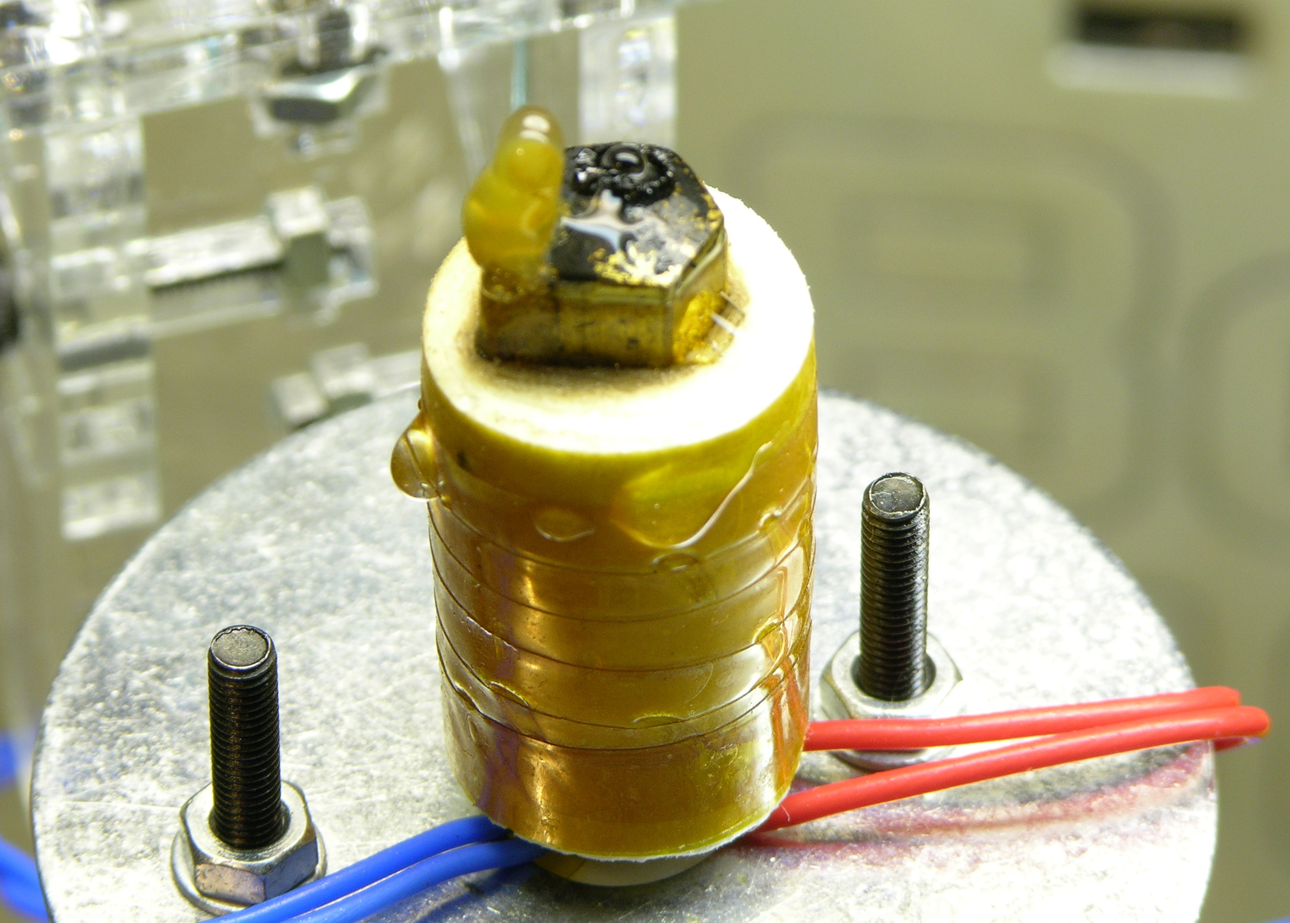
By the time I was done with the re-test of temperature readings, this sap-like drip had formed on the extruder nozzle, on the edge below the thermistor. I’d had the end of my ceramic insulator “blanket” and kapton tape sitting in the boiling water, and I don’t know whether the water interacted with the thermistor, the insulator, or the tape.
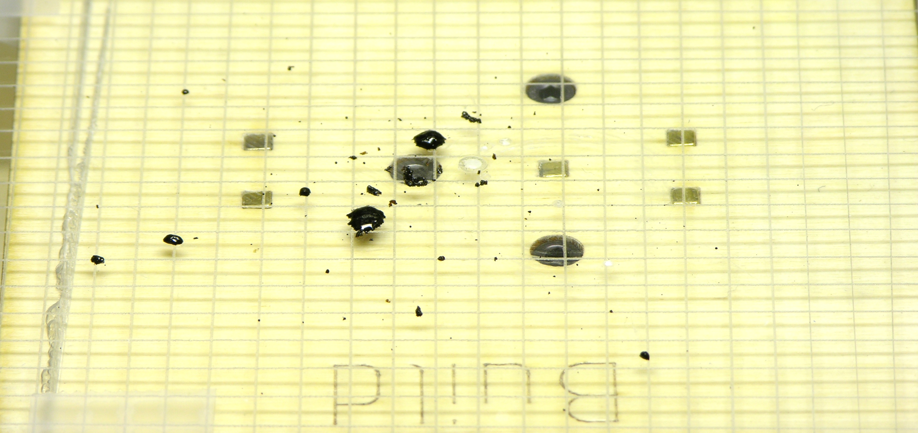
After taking the nozzle out of the water and cleaning off the “sap,” I turned on the heating element and slowly raised the temperature for a while, to heat off and then boil off any water remaining in the assembly. I didn’t see when it happened, but I later found these drips on the build platform.
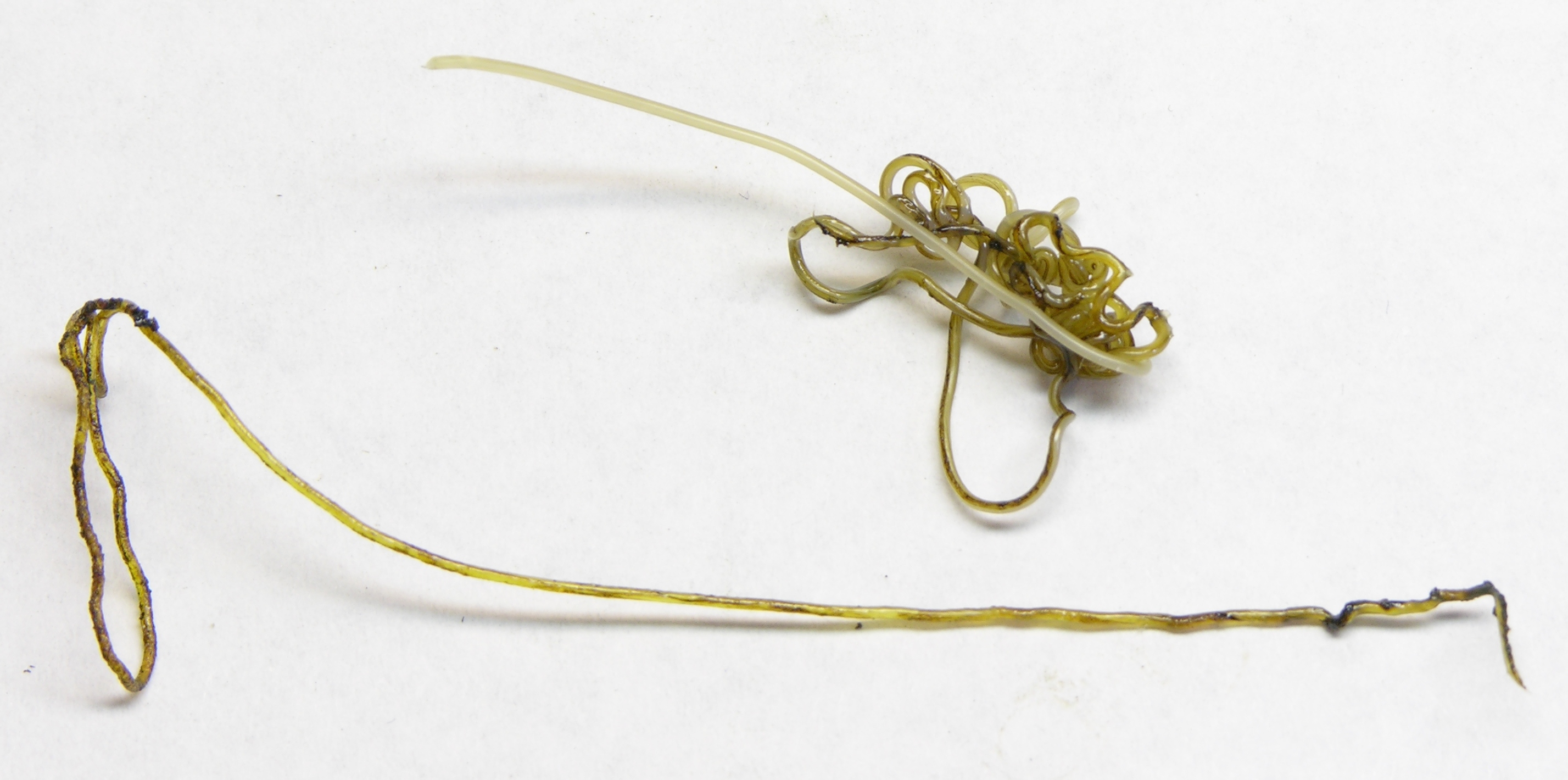
And the first plastic to extrude from the nozzle after I was done was gross, which makes me think some of the black drippiness may have come from inside the nozzle. Any ideas?
Lesson: Only dip the nozzle tip, and not any other part of the heating assembly, into water for calibration. I think.
The boiling point of water decreases about 1 degree F for every 500 ft increase in altitude. So the boiling point of water at a pressure altitude of 1,500 ft is 209 F or 98.3 C. That’s a difference of 1.7% which is well within the tolerances of your measuring equipment.
Steve, thanks!
That changes my beta from 3736 to 3783 which in turn changes my ADC reading of 107 from a reported temperature of 225°C to 220°C.
It means that my boiling-point reading, which must have been an ADC value between 584 and 637 — let’s call it 605 — probably drops from a reported temperature of 99°C to 97°C.
Grrrr.
I wonder whether part of the problem isn’t that my two sample data points are so close together, at least relative to the actual temperatures this will be measuring in operation. Anyone know of a physical phenomenon that would give me a constant, predictable temperature in the 200-250°C range?
I think your problem with the infrared thermometer is the shiny brass surface of the nozzle. They work best on a flat black surface. Check out the section on emissivity here:
http://www.omega.com/prodinfo/infraredthermometer.html
I know from experience with hot glue guns that for some reason, be it impurities or something else, the nozzle just starts to turn all black and gunky. That probably happened to your Cupcake, and when you put it in the water it dislodged or moistened some of it. So you were extruding (carbon?) gunk for a bit, but it’ll go away.
Nick, thanks for the fantastic article — promotional though it may be — on infrared thermometers! Do you have another one on exactly what the pyroelectric sensor is measuring? I could never reconcile the ideas that the body will be putting out different wavelengths of infrared light at different temperatures and that the pyroelectric sensor is probably sensitive to different amounts of infrared peaking at a single wavelength.
I actually didn’t try using the thermometer on the CupCake nozzle; I’ve been suspicious of it for a while already and didn’t even bother. But it’s plausible that the things that have been giving me trouble are too shiny. I’ll pay particular attention to that for a while and see how it goes!
Aaron, I know what you’re talking about with glue guns, I’ve seen it myself, and I have the same thing happening on the outside of the CupCake nozzle. But I’m surprised to think of it happening on the inside — I assume it’s partly an oxidation process, and there’s not normally much oxygen inside the nozzle (since it’s filled with plastic).
I can’t say that isn’t what was going on, but I’m not convinced yet, especially in conjunction with the weird growth on the outside.
I don’t think the water needs to touch the thermistor to do this. You could probably wrap the nozzle in a plastic bag (like those finger condoms mechanics use to protect their cut fingers from grease) and submerge that in the water.
You could also use a thermometer to measure the temperature of the water, so long as it measure temperature more precisely than the thermistor.
I’d really like to drill a hole through the nozzle’s side to insert a thermocouple directly into the extrusion material.
Charles, good idea on waterproofing the nozzle for the test. The waterproofing material just has to withstand boiling, not extrusion temperatures, of course.
I’d really like to see (software) PID control on the nozzle temperature. It does take some of the joy out of calibrating the thermistor to watch the temperature still swinging wildly between 220 and 240°C.
I wonder if there is an IC Temperature sensor, like the LM35, which would operate at Makerbot temperatures? The LM35 only works up to 110C, but gives a nice linear reading of .1v per degree. Much better for precise readings! I’m gonna go IC shopping and find out..
Cathal, the IC sensor is a tantalizingly simple and accurate idea.
The snag, I’m afraid, is that common leaded solder melts in the 180-190°C range, significantly lower than the 220°C range of ABS plastic. I suspect that manufacturers won’t have been strongly motivated to make IC sensors with measurement ranges that would have them floating loose from their solder connections.
I had a quick look at National’s parametric search and none of their sensors go about 150°C.
Of course one could crimp (rather than solder) wires onto a TO-92 package. If you find something, let us know!
For the temperature/pressure of boiling water, you can always consult the CRC Handbook of Physics and Chemistry, which I used to compute about a 1.7K difference in temperature due to your altitude.
Dave
Hi Keith, .
.
I calibrate my thermistor with a multimeter / thermocouple combination. I put the thermocouple inside the nozzle. It is easier to do when the nozzle is new and does not have plastic inside of course
You don’t need PID to get good control. I get swings of +-1-3 C with simple on off. The thing that is different is that I convert the temperature to ADC value once on the PC and send the value to the micro which then compares that with the ADC and turns the heater on and off thousands of times a second. I don’t have any table interpolation either.
The black stuff looks like burnt filament. If you heat ABS to extrusion temperature and leave it in the presence of air then it will burn. Best not to leave stationary filament cooking for more than a few minutes as it can block the nozzle.
Nophead — yeah, before assembling the whole thing would have been a great time to calibrate the temperature.
Thanks for the note about using PWM but no PID for the heater. I think I need to have a lookie at the extruder code — I can see by watching the indicator LED that it’s doing bang-bang, and maybe we can do something better.
+1 for Spam eating and can usage!
I’ve had a good look and got a response out of National Semiconductor on the high-temp IC idea. Turns out they’re soon to release a new chip that can sense as high as 200˚C! Great, but not quite there yet. Perhaps for lower-temperature plastics? I gather PLA prints at lower temperatures.. though I’m still looking for a supplier of PLA in coil form.
I’ll throw an idea out here for you. If you used an oil, like peanut or safflower, instead of water you can measure to temperature closer to where you want to operate. They have smoke points around 450 F (232C). If you used a good kitchen thermometer, like a fry or a digital probe thermometer, you can plot your thermistor reading over a wider range of temperatures. I doubt that the thermistor has a linear curve so I would want to have multiple readings and have it calibrated accurately to the temperature I want to operate at.
With regards to IC/solder temp/probe(thermistor) temp: IC based solutions are a bad idea; reliability and longevity are poor when stressed to the extremes needed for thermo-plastics. NTC Glass encapsulated thermistors are reliable, quick to respond, stable and have better than 3% tolerance. Platinum RTDs are choice for precision & long term stability.
In the Past we’ve used mineral oil for heat dissipation , especially in conductive situations, – a Paint can full of oil- as dummy antenna load for 2kw linear RF amps.
a similar mineral oil filled can may be just what the doctor ordered, fill your spam can with unscented mineral oil and give it another go – the mineral oil holds heat much better than water, is electrically non-conductive , and DOESNT bother anything you may have soldered, (or kapton tape)
Hoop, because I don’t have a thermometer I trust, I was looking for a physical phenomenon with a known temperature. I’m less certain of the boiling point of mineral oil than I am of that of water, so that’s not a good fit for me.