Archive for the ‘Robotics’ Category

How to Make a 4046 PLL Work

Friday, January 13th, 2006

Success! I have the PLL locking onto the ADXL202 now, and my LEDs indicating tilt, all thanks to Lab 4: CMOS 4046 Phase-Locked Loop from a 1997 class at UC Boulder that I found via Google. Thank you, thank you, thank you for putting your courseware online (and leaving it there, apparently indefinitely)!

The lab explained two salient points that I hadn’t seen previously:

1MΩ ≥ [ R1, R2 ] ≥ 10kΩ
100nF ≥ C1 ≥ 100pF

and

How to test each subsection of the chip independently to building a working circuit from the ground up

So here are the values I ended up using. C1 = .1μF and R2 = 100KΩ gave fmin quite a bit slower than my sensor’s 80Hz output, but that was the closest I could do with what I had in my parts bin. Likewise, R1 = 68KΩ gave fmax quite a bit faster than 80Hz, but again, it’s what I was able to do with what I had on hand. I was able to test each of these frequencies and confirm correct operation individually by connecting VCO IN to ground (fmin) and to VDD (fmax) with no SIGNAL IN, and counting hash marks on my scope.

For the low-pass filter (R3 and C2), the cutoff frequency should be much smaller than twice the frequency of the incoming signal (sounds vaguely Nyquistish, eh?), in order for VCO IN to get the average DC component of the phase comparator output. I scratched and calculated a bit, but wasn’t really enjoying it, so picked values I knew would set the cutoff far lower than 160Hz–R3 = 1MΩ and C2 = .01μF. The price of my sin of laziness is that the circuit takes a few seconds to lock onto the input signal at powerup, but I can live with that for now. And because my input signal doesn’t have a strict 50% duty cycle, I’m using the Type II (edge-triggered) phase detector.

I also connected INHIBIT to ground. I don’t know whether it was strictly necessary, but another posting recommended doing so with unused CMOS inputs. It only cost me one more jumper to ground it, and as much trouble as I’d had already, I wasn’t going to let one more little thing stand in my way. Of course, I wired the tilt sensor’s output to the 4046′s input.

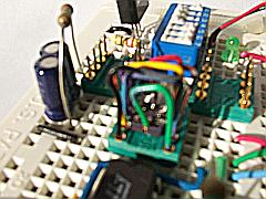
And everything worked at last! As noted above, the PLL takes a couple of seconds to lock to the input signal, but once it does, it’s rock-solid every time. It’s encouraging to see that once the capture range is set properly, the 4046 really works predictably. The scope shows the signal wiggling on power-up, but then it settles down.

I also got to use the external trigger input on my scope. I was wishing for a dual-trace scope so I could trigger off the sensor signal and compare it with the PLL signal on the same screen. Can’t do that on my single-trace, but I’m doing the next best thing–using the sensor signal as an external trigger to lock the PLL signal into position. True, I won’t be able to detect very small phase differences this way; but within the resolution of my scope, it sure looks as though they’re in phase.

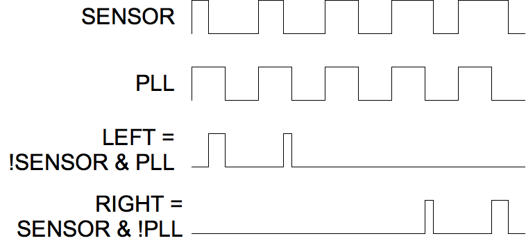
I wired up a 7406 and 7400 to give me the !SENSOR & PLL and !PLL & SENSOR combinations I described earlier, hooked them up to a couple of LEDs, and voila! Visible indication of the operation of my tilt sensor. A little more wiring, and I had four LEDs indicating bidirectional tilt. (Thank goodness the ADXL202 appears to use the same frequency generator for both axes’ PWM outputs, so I didn’t have to wire up another PLL for the Y axis.)

It works great! It works so well, in fact, that it demonstrates that I have the sensor positioned not quite level. And while I was fiddling with it trying to level it, I caused some intermittent connections on its contacts to its carrier. Oh well. It mostly works, and I know how to make it work, and I’m pretty happy about that.

POSTING IN PROGRESS

Solid-State Tilt Sensor with a PLL?

Thursday, January 12th, 2006

In order to show off the ADXL202 tilt sensor, I want to hook up two LEDs that brighten and dim in response to the tilt. Because the sensor is +/- 2g, my PWM duty cycle is only varying from 25% to 75%, which isn’t enough to see the variation in brightness of my LEDs. Somehow, I have to translate that into a range that varies down to near 0%.

My ultimate plan for the tilt sensor involves controlling a motor (duh), and I expect to experiment with several different drive logic configurations. Regardless of how I end up driving the motor, though, it’d be nice to have indicator LEDs to demonstrate what decisions are being made and fed to the motor–so even if I don’t need any additional circuitry for the motor drive, I’d like to get the LEDs working.

I had previously considered, and am now looking carefully, at using a phase-locked loop (PLL) to help decode the PWM signal. A PLL locks onto the input frequency and provides an output signal of the same frequency–but with 50% duty cycle. A Type II PLL is edge-triggered, so it provides an in-phase output. (A Type I PLL’s output is nominally 90 degrees out of phase for a 50% duty cycle input.)

So if I can manage to get a PLL to work, I can use it to lock onto the fixed frequency of the tilt sensor’s output, and give me a reference signal that goes high at the same time as each pulse of the sensor, but goes low at exactly half of the signal period, while the sensor’s signal is going lower earlier or later depending on its tilt. Then instead of looking at the raw sensor data with a duty cycle range of 25% to 75%, I can compare the sensor to the reference and get “left” and “right” signals with duty cycles each varying from 0% to 25%.

ADXL202 and PLL

That means the LEDs would both be dark when the device is level, instead of each varying from dark to bright over the whole range–but I can live with that. It also means the LEDs will give a very direct representation of what I need the motor to do.

So I picked up a couple of 4046 PLL chips, and I’ve been reading the datasheets. Many, many times. After three or four readings, I understood that they were really going to do what I want with their Type II phase detectors. After another three or four readings, I think I have a pretty good idea how to select external components to set the frequency capture range I need. I don’t think I’m stupid–I’ve just never worked with these before.

I’m itching to try it out.

Solid-State Tilt Sensor, Unplugged

Thursday, January 12th, 2006

Having got the ADXL202 working, I wanted to show it off, and then get it installed in a little project that I’ve had waiting in the wings. Showing it off has the side benefit of demonstrating the accuracy of my assumptions about how it works and how it interfaces, above and beyond being able to view its signal on my scope.

So this weekend, I breadboarded some LED drivers onto the sensor. I didn’t remember how much current the ADXL202 would source or sink; plus I wanted one LED to get brighter when it tilted left and another to get brighter when it tilted right. So I plucked a 7404 hex inverter out of my parts bin and wired one of the ADXL202′s outputs to a couple of inverters, then the output of one of them into a third inverter. This gave me two buffered outputs, one inverted and one non-inverted, which I wired through resistors into a couple of LEDs.

And because I wanted it to be portable so I could show it off, I left the benchtop power supply behind and strapped on a 9V battery and a 7805 voltage regulator. I cleverly soldered the black and red leads onto the wrong terminals on the battery connector, which I didn’t discover until I had covered the solder joints with nail polish (pink coral, if you’re curious) and cleverly smeared it around the breadboard when I accidentally touched the connector before it was dry.

Since the sensor’s PWM output is dramatically visible on the scope, I figured it’d be dramatically visible on the LEDs. Wrong-uh. Even knowing what was supposed to be happening, and with the LEDs’ domes carefully aligned in the same direction, in a dark room, I could just barely tell that one brightened and one dimmed as I rotated the assembly back and forth.

Feh.

Well, the ADXL202 is a +/- 2g sensor, and tilted vertically, it’s only experiencing 1g. That means my PWM duty cycle isn’t changing from 0% to 100%; it’s changing from 25% to 75%. I would still think that’d be enough to see a difference in brightness of my LEDs!, but apparently not. So I have to get smarter.

Solid-State Tilt Sensor

Thursday, January 12th, 2006

Years ago–probably about 2000, shortly after I got my first Handspring PDA–I saw an article on adding a solid-state tilt sensor to your Palm computer. I was enchanted by the idea of playing games by tilting the PDA from side to side, but even more excited about the possibilities for walking, balancing robots.

After reading about Analog Devices’ ADXL202, a micro-machined +/- 2g accelerometer with pulse-width modulated (PWM) digital output, I filled out their sample request form and received two chips in the mail. Unfortunately, I ordered the LCC (brick with leads painted onto the surface) instead of the small-form-factor surface-mount chip, thinking I’d find an LCC socket for it. Alas, I never did locate one.

I had long thought I should make some kind of daughterboard for the chip, with DIP pins on the underside to make it easier to use for prototyping. Fast-forward to 2005. After I was no longer commuting to Pittsburg, I had much greater continuity of free time between weekday evenings and weekends. I also had all my spare junk in one place. :-) I desoldered a larger LCC socket from a scrap board and cut opposing corners out of it with a razor saw, thinking I might be able to glom something together that would work, but to no avail.

Finally, late last fall, I did what any self-respecting (or was that desperate?) tinkerer would do: I soldered leads to the chip and stuck them into the top side of a machined DIP socket. It’s gross. It’s tacky. It’s done and it works.

ADXL202 carrier

The machined pins on the DIP socket fit very nicely into another DIP socket, and it works perfectly on my solderless breadboard. After assembling the carrier, I added the supporting components and a power supply, and was at last able to confirm that the device worked! I hooked it up to my scope and tilted it back and forth, enthralled by the tidy constant-period waveform with the high region changing width as I moved the board. W00T!