My wife isn’t interested in electronics. She doesn’t do electronics, she doesn’t understand electronics, and she really doesn’t want to hear me ramble on at length about electronics. (I say this all in a very good-natured way, of course. Identical interests were not a prerequisite for our marriage.)
So when my wife asks my why I keep soldering chips onto boards in the wrong direction, I know I have a problem.
Oh, and the ADXL202 is a hardy little sucker.
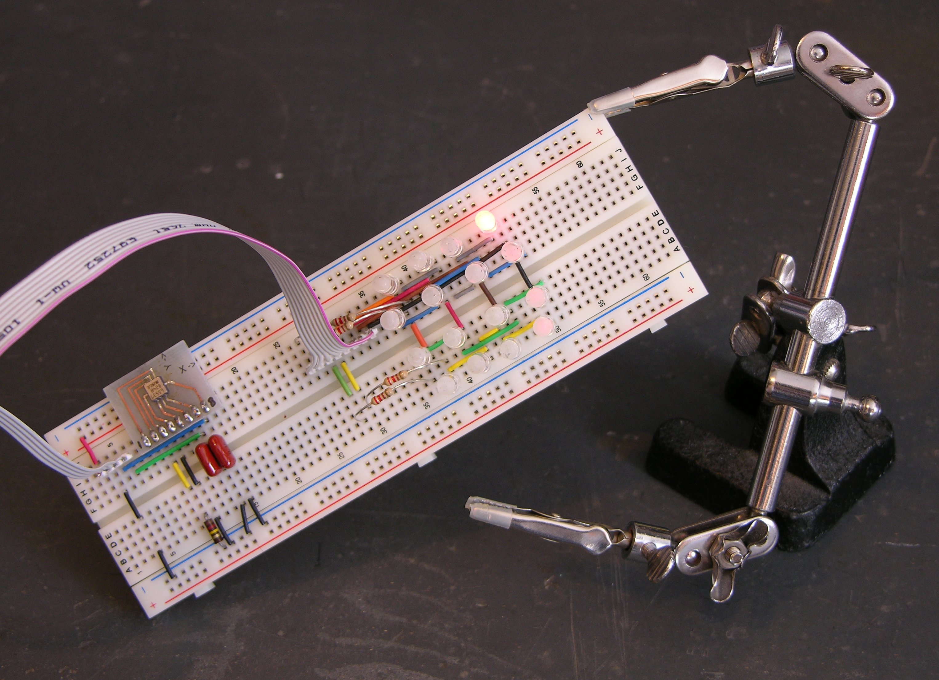
Prototype Puck I/O Board
Over the weekend, I laid out and built a prototype of the I/O for the puck — just the LEDs, their driver, an accelerometer chip, and a pushbutton. I expect to use the Freeduino circuit for the microcontroller and will still need to add it to the board (as well as battery-charging circuit and all that other good stuff); but I wanted to get started programming the actual LEDs and tilt system.
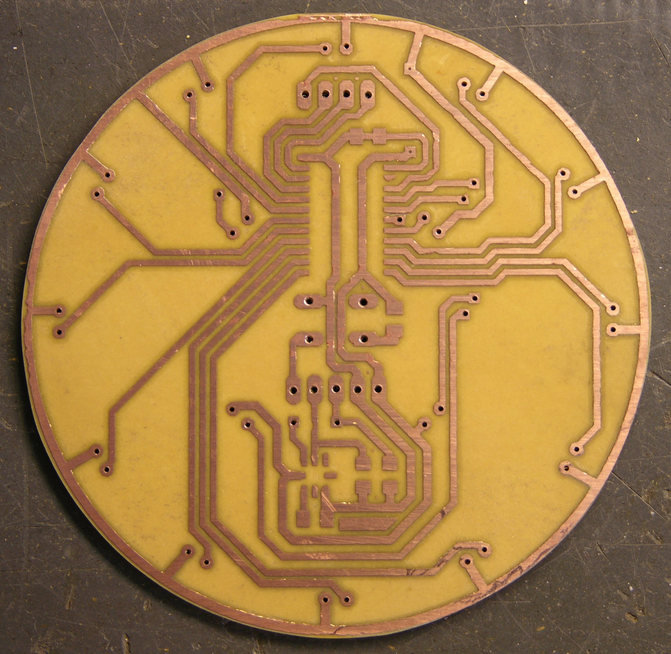
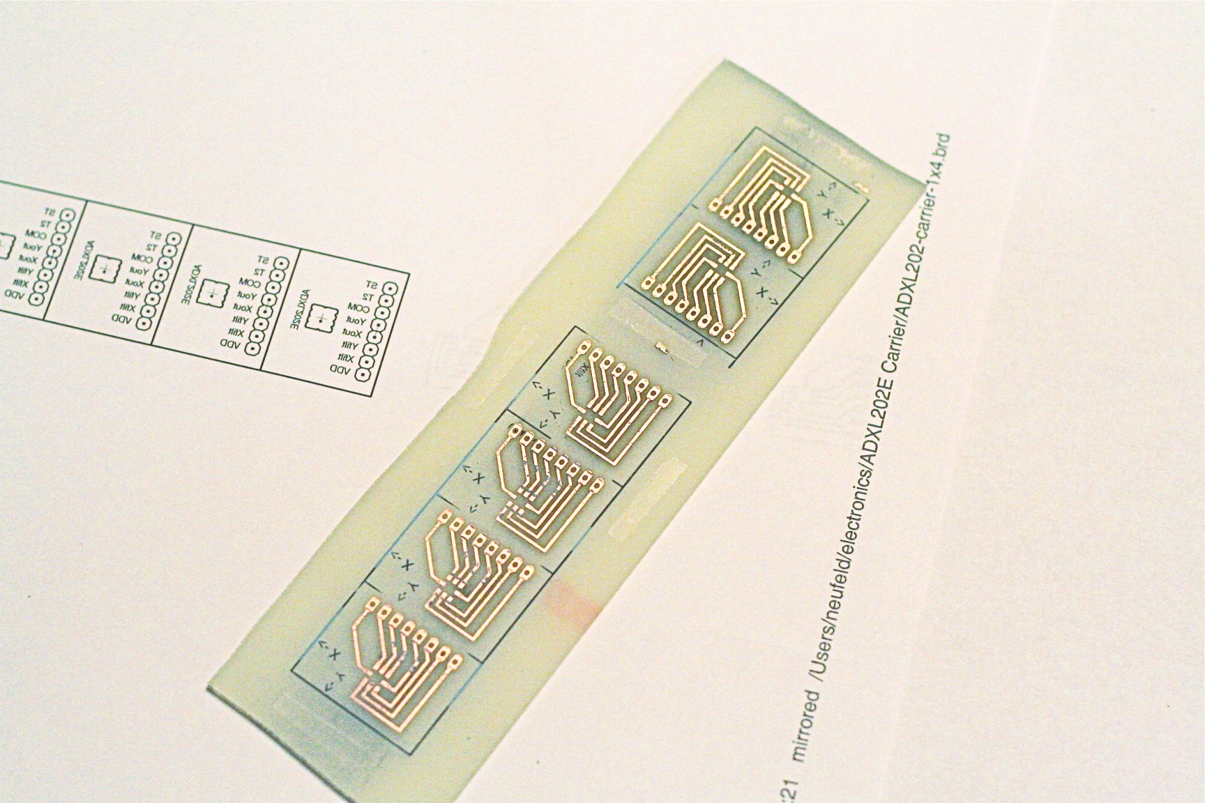
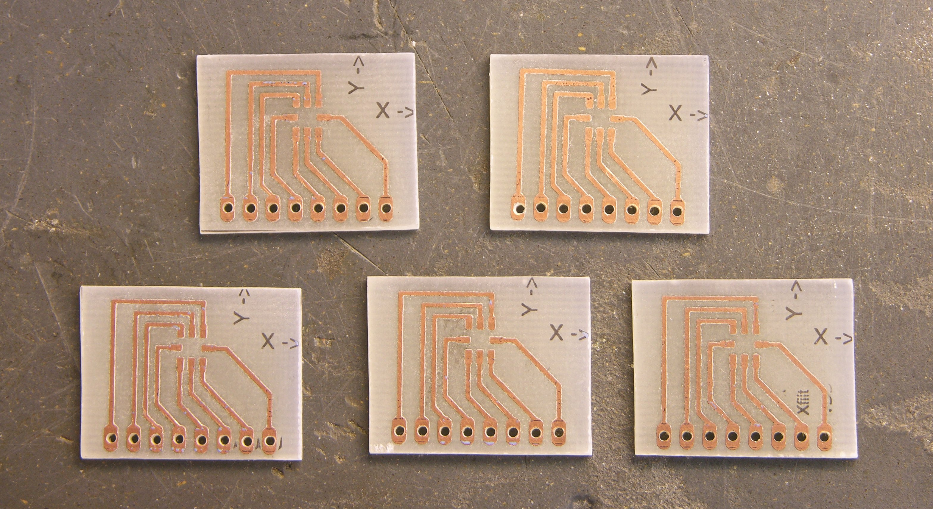
I laid out the board in EAGLE; and believe me, it’s a bit of a challenge routing nice curves as traces. The V+ circle around the edge wasn’t too bad; but I wanted to route the LED drive traces as concentric arcs and just couldn’t find a way to do it.
I had a few SMT A6276 LED driver chips around, so I was able to make most of the board SMT already. The A6276 will want to be on the underside of the board (shown here) so its pins are in the same order as the LEDs it drives. I’m not sure where the other chips should be, but it was easy to make a single-sided board for this prototype.
I worried that I was packing the traces too closely together; but they came out well enough (iron-on toner transfer), I think I could have made them smaller. And having to run to headers to go off-board to the Arduino complicated the routing; if the microcontroller were on the other side of the board, each of those signals could have gone through on a via wherever it was convenient rather than having to converge to the two headers at the top and center.
Tinnit
I tried plating the board with Tinnit, because I had such good results last time — that board was incredibly easy to solder. Alas, five-month-old eighteen-year-old Tinnit apparently doesn’t work very well. After forty minutes at 110°F with no plating appearing on my traces at all, I gave up, washed the board clean, and dumped the rest of the Tinnit.
I still think it’s great stuff and I intend to use it again. I just need to be sure I’ll be making enough boards for it to be worthwhile.
I did learn something else, though. After cleaning the board, it sat out for a few hours, and I noticed that it was already oxidizing — the copper was considerably less shiny than when it was fresh. Before soldering, I polished it with wet 600-grit sandpaper, and it took solder beautifully — completely unlike untinned boards I’m used to soldering.
Lesson: If a copper board has been exposed to air for even a few hours, polish it with wet, fine sandpaper before soldering.
Assembly
I soldered on all the SMT components first. I was pleased that I was actually able to find all the resistors and capacitors I needed in my salvage bin. I’ve desoldered a number of SMT boards (heat with heat gun, then bang on the bench vise and the components come flying off; or pluck them off with tweezers for a more orderly approach), and I think these came from a dead Cabletron hub.
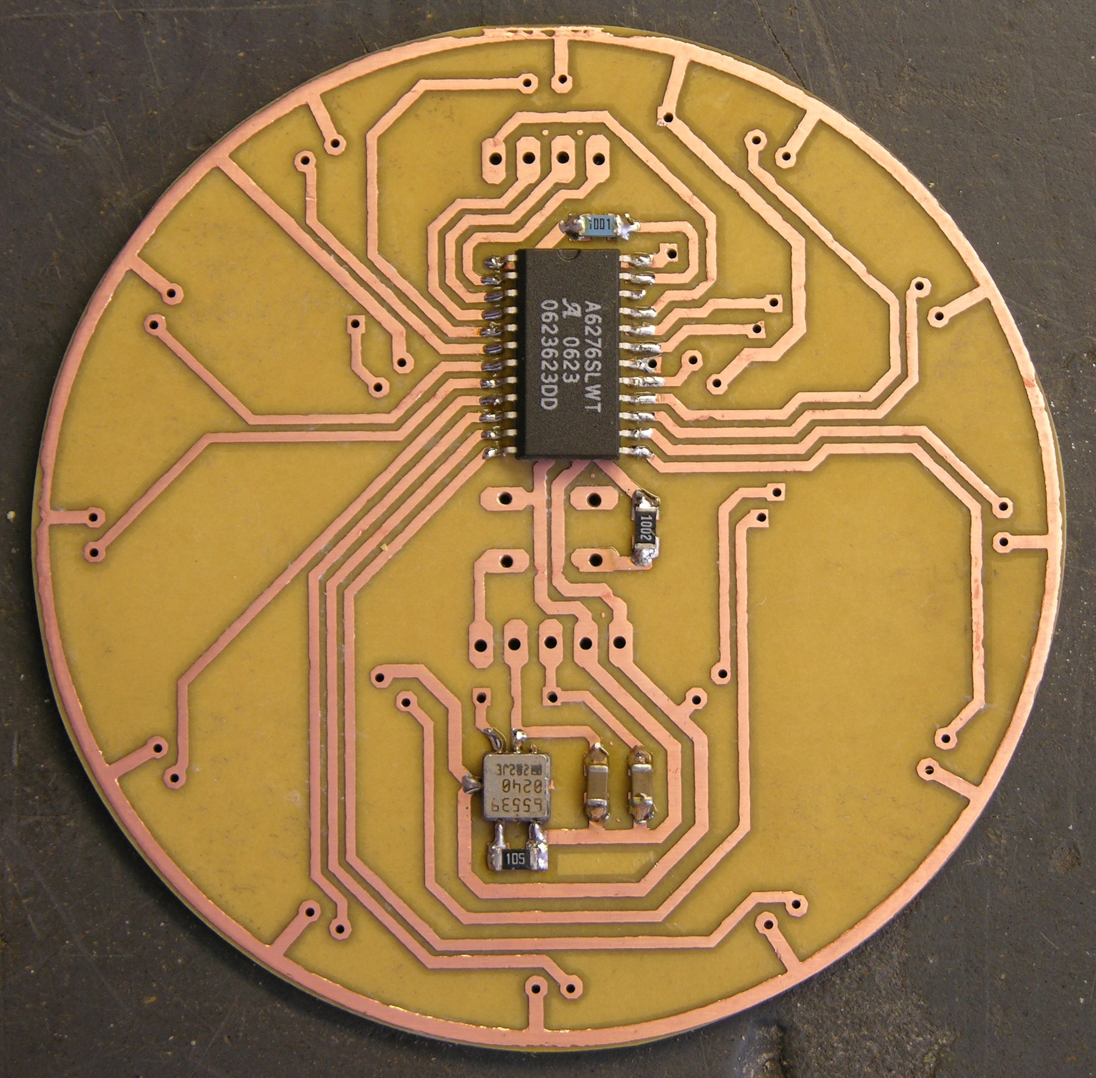
The resistors were all labeled, so they were easy to search for the right values (if you call picking through a bag of grains of rice easy). The capacitors were a bit more challenging — they were completely unlabelled, so I had to dump them out on the workbench and use the meter (tweezer-style) to find the values I needed.
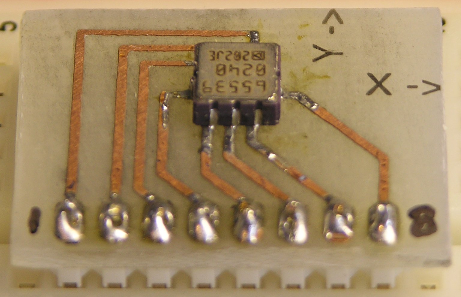
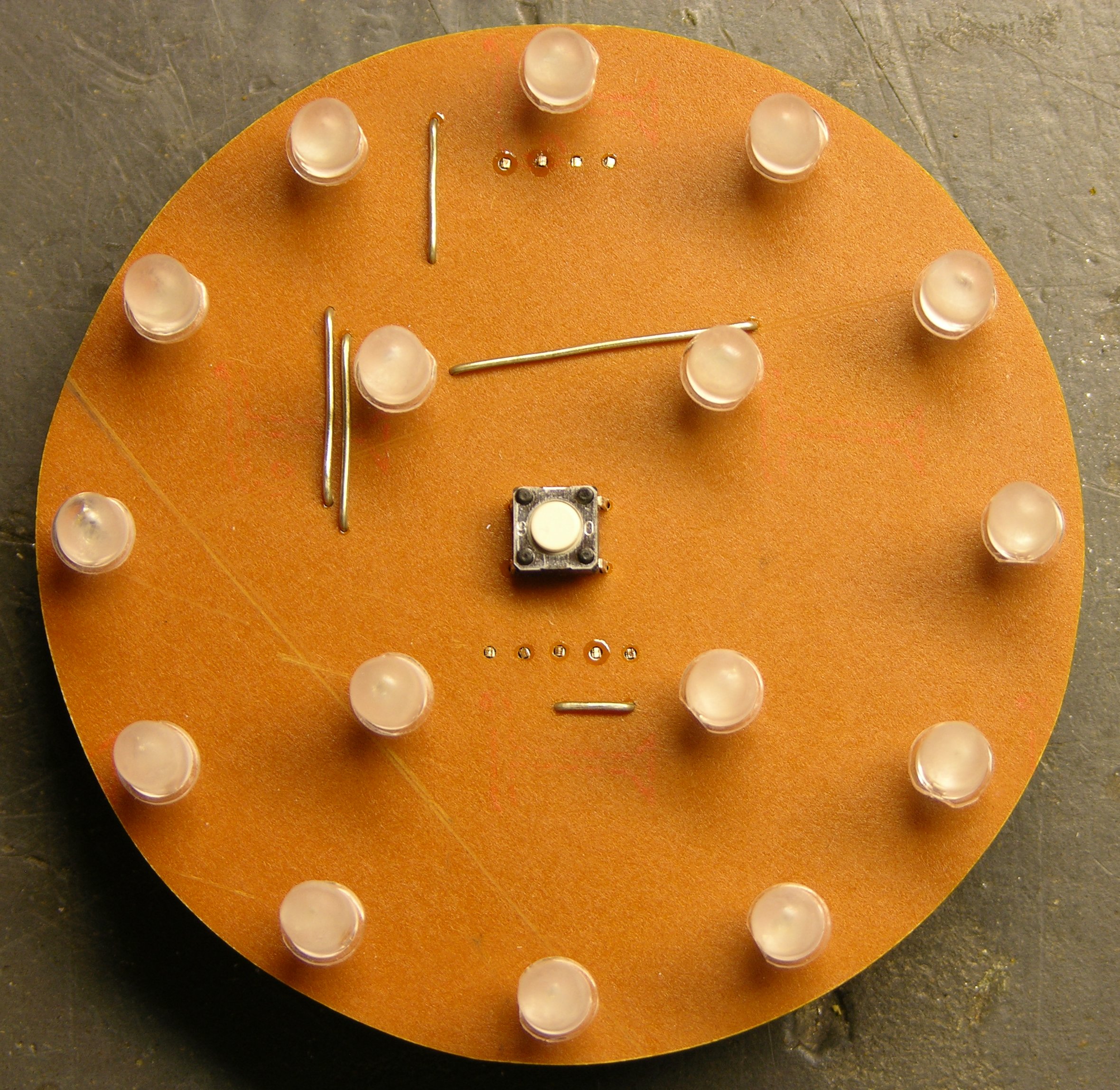
I placed all the LEDs with their cathodes facing clockwise (as viewed from the top) for simplicity — so I wouldn’t have to think about which way each one goes. Although parts of the puck are obviously asymmetric, I prefer to think of the puck as a whole having at least rotational symmetry, and I wanted the LED orientation to reflect that as well.
The jumper wires are a bit scabby, particularly the one running halfway across the board at an odd angle; but again, they’re at least partly due to routing challenges with not yet having the microcontroller on board, as I mentioned earlier.
I should stop to add that laying out an SMT board is really refreshing, in that you can fill both sides of the board with components and traces, and not worry about through-holes impacting the routing on the other side of the board. As long as you don’t need to hop to the other side and back to cross one trace over another, each side can be completely independent of the other.
That’s not illustrated well by my single-sided SMT board; but I mention it because I’m really looking forward to laying out the microcontroller (probably on the top side) and cleaning up some of these traces and jumpers.
Two Mistakes on the Accelerometer
First: absent-mindedly running the resistor that sets the PWM output period to the self-test pin by mistake. Second: soldering the accelerometer to the board 180° from its proper orientation.
When I first powered up the board, I was most interested in testing the LED driver, since I had already tested the accelerometer on the breadboard. The lights didn’t come up (I had forgotten to manipulate the output enable line in my program), but I also smelled hot electronics. I fixed the program, the LEDs worked, the accelerometer didn’t, and I realized my mistake.
On the EAGLE PCB layout, I had a marking for the accelerometer orientation, of course. But the marking was on the silkscreen layer, and I didn’t make a silkscreen layer when I etched the board at home. Then because the components are on the bottom side, I got myself confused about which end of the accelerometer was which.
Lesson: Copy IC orientation markings to the copper layer for homebrew boards.
Rework
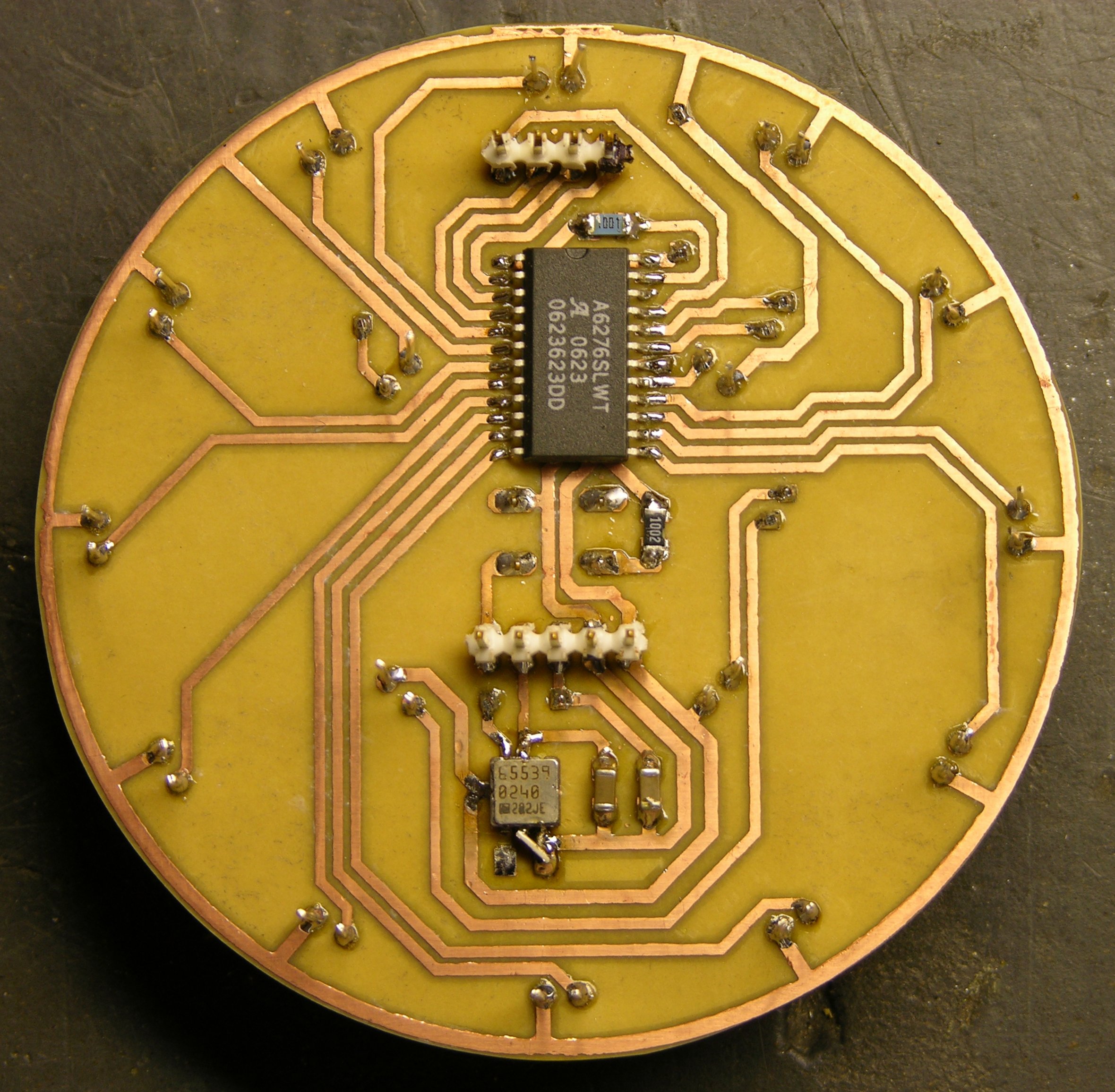
Last night I waved my soldering wand and cast a spell of devious reparo on the accelerometer chip; but apparently it backfired, because it ended up looking like this.

I actually used solder wick to remove the errant PWM period resistor — it did a nice job of sucking up solder, heating both ends at the same time, and then scooting the resistor off its pads so it wouldn’t stick back down when the solder cooled.
I used solder wick to suck up all the solder I could from around the accelerometer; but I didn’t have a way to heat the whole thing at once, so I couldn’t scoot it away. I need a hot-air pencil and looked at several DIY designs, but didn’t want to take the time out to build one. There was little enough solder left, I was able to twist the chip off the board with a pair of pliers.
I lost a couple of pads in the process; but when I soldered it back down, one was NC and the other I was able to bridge with solder. Then I needed to move one of the resistor traces from the left pin to the middle . . . and the easiest way to do it was to solder one end of the resistor directly to the chip.
Yes, I’ll fix it right in EAGLE for the next board.
BTW, notice the stacked SMT capacitors on the right. I couldn’t find anything in the .1uF – .2uF range in my bag, so I paralleled a couple of 75nF. Nasty!!! ![]()
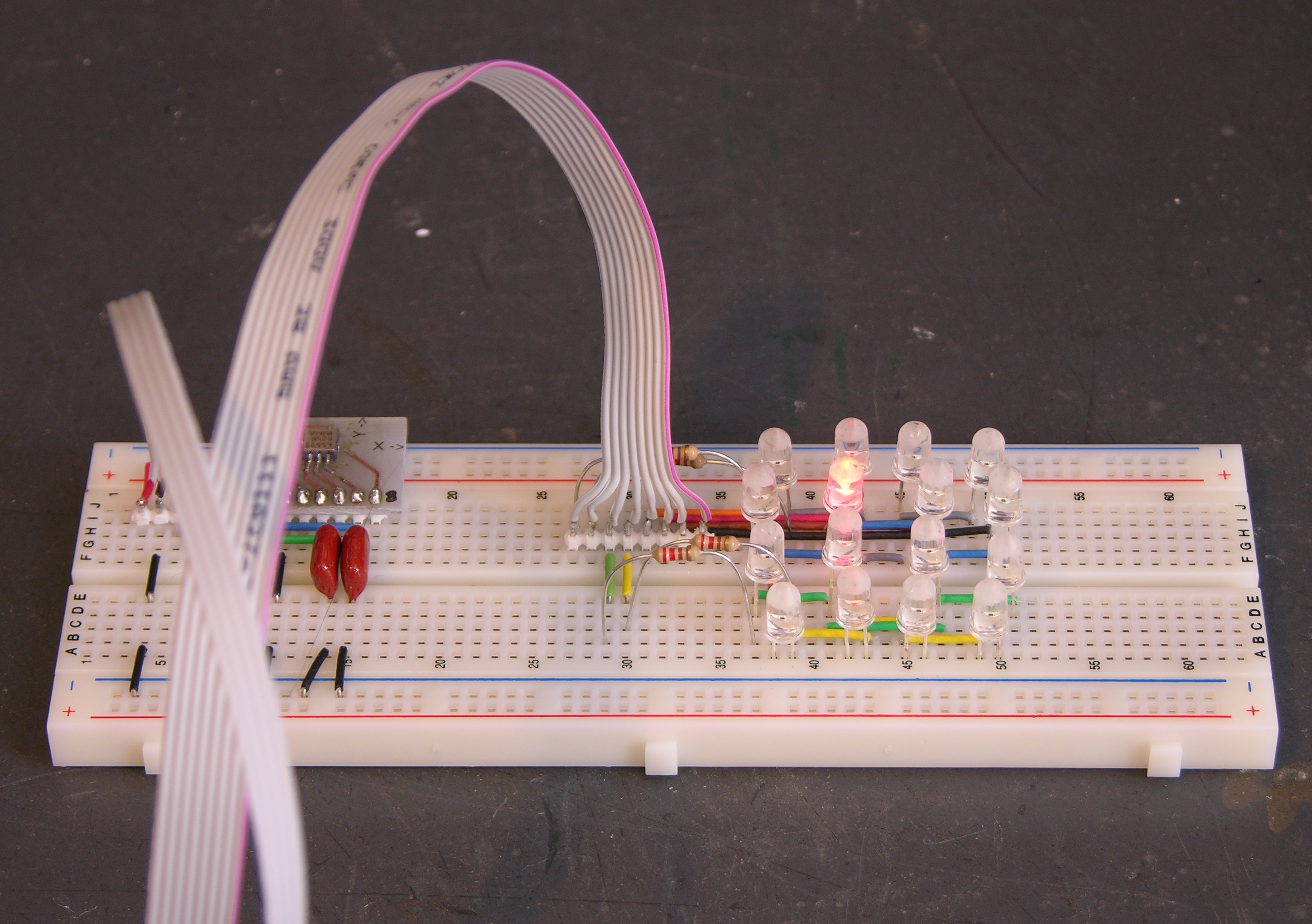
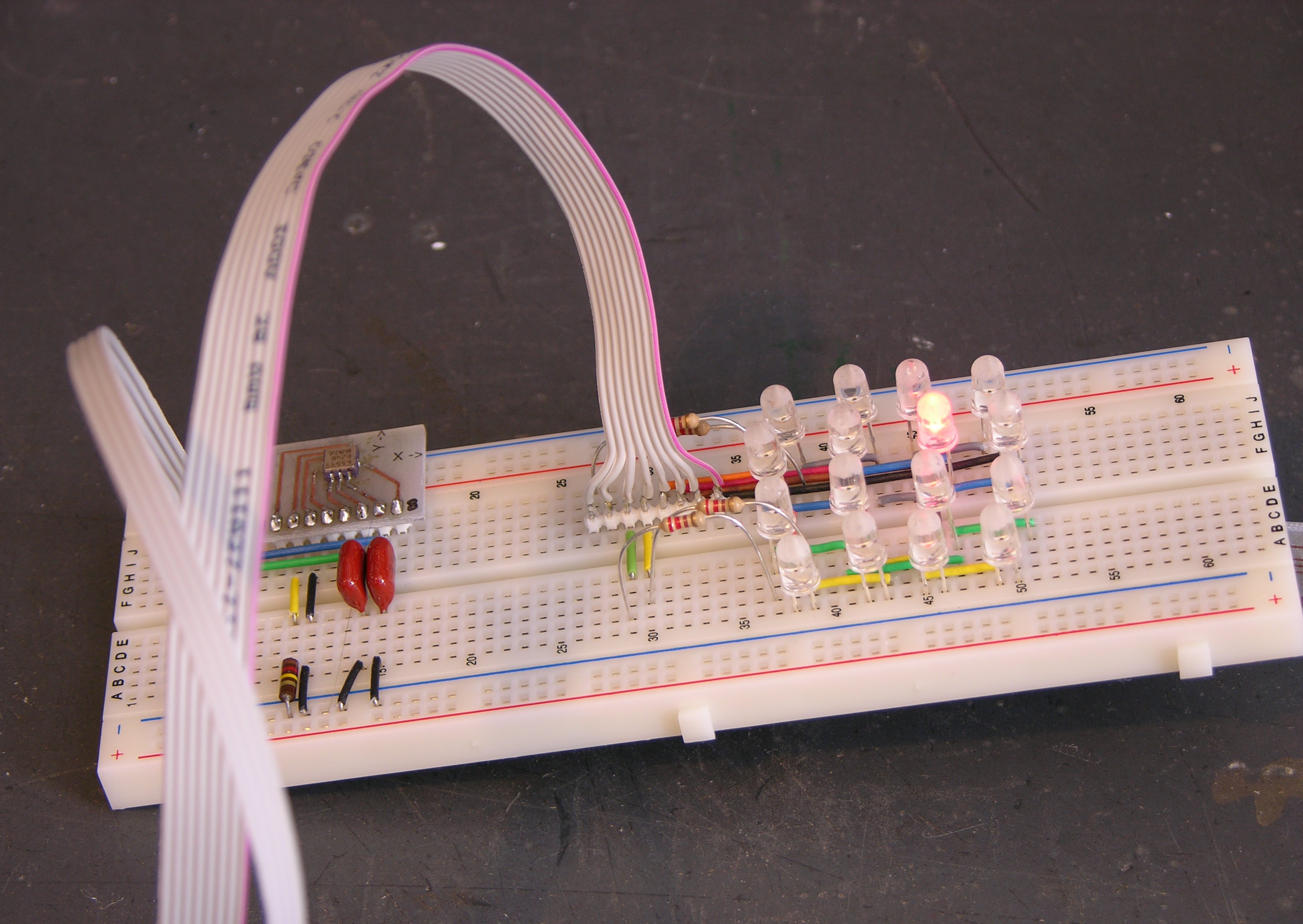
Proto-Puck
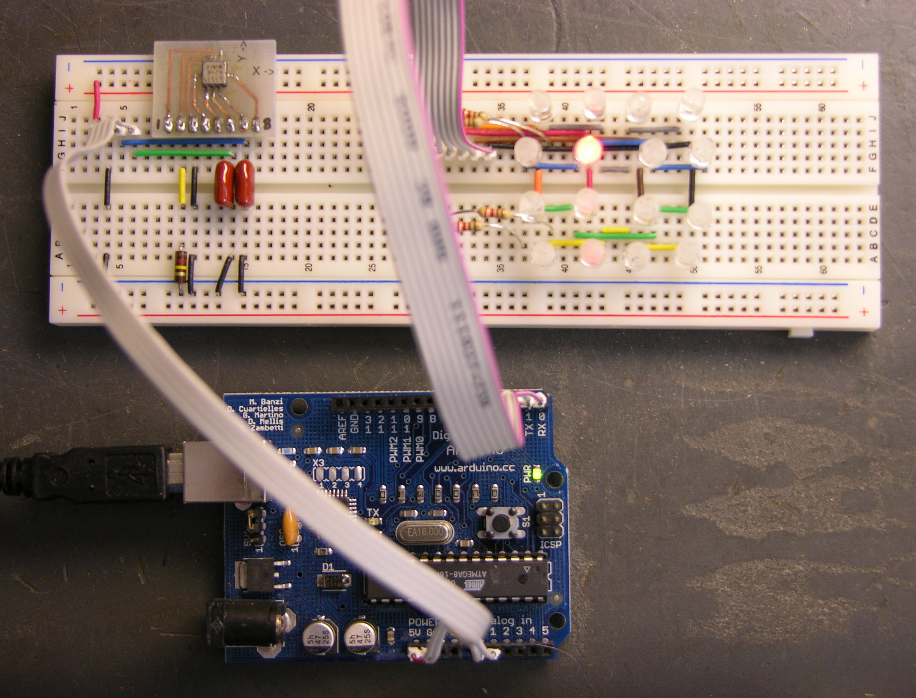
The upshot of all this, if I can finally get to the point, is that I have a working proto-puck.
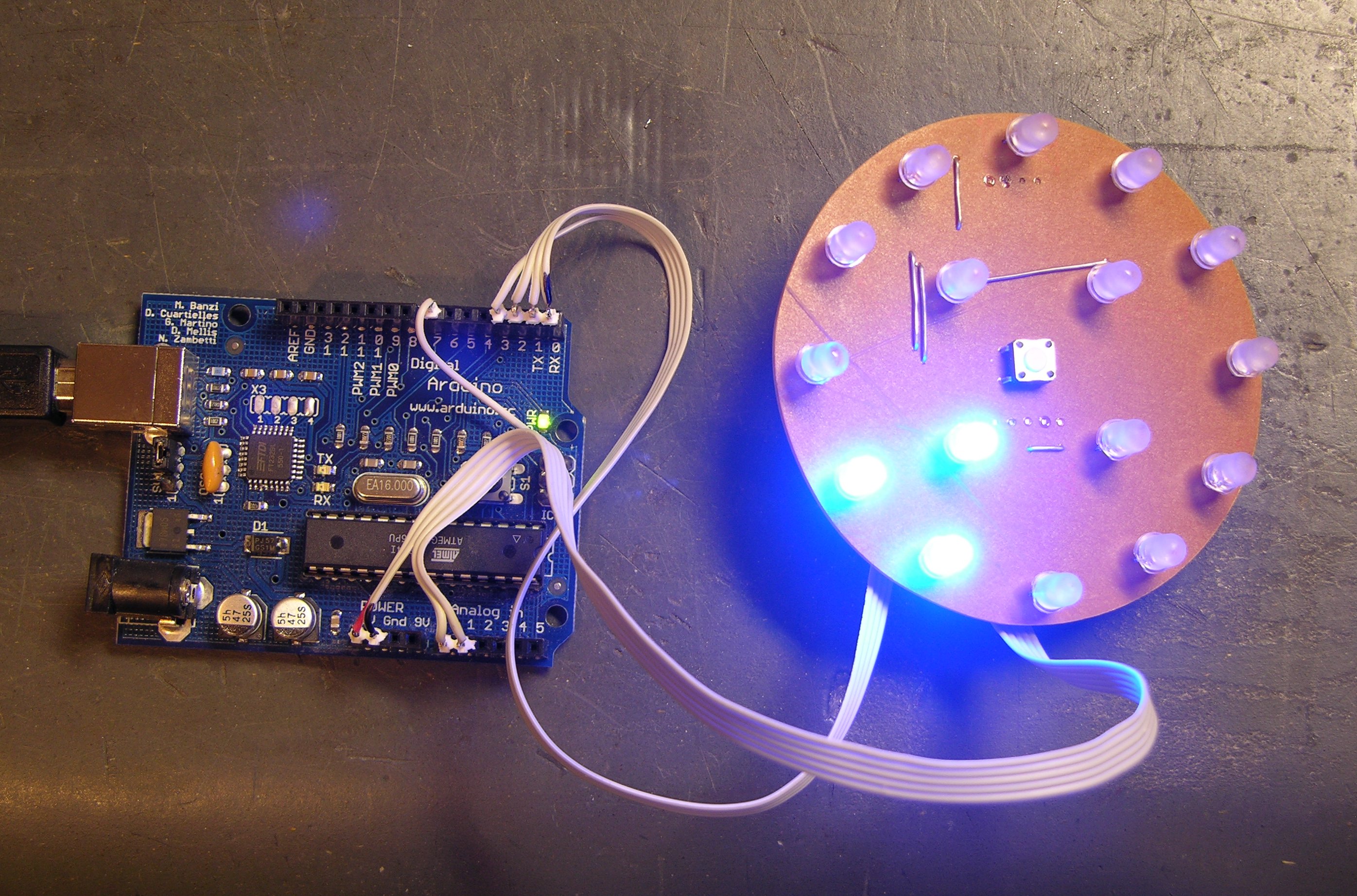
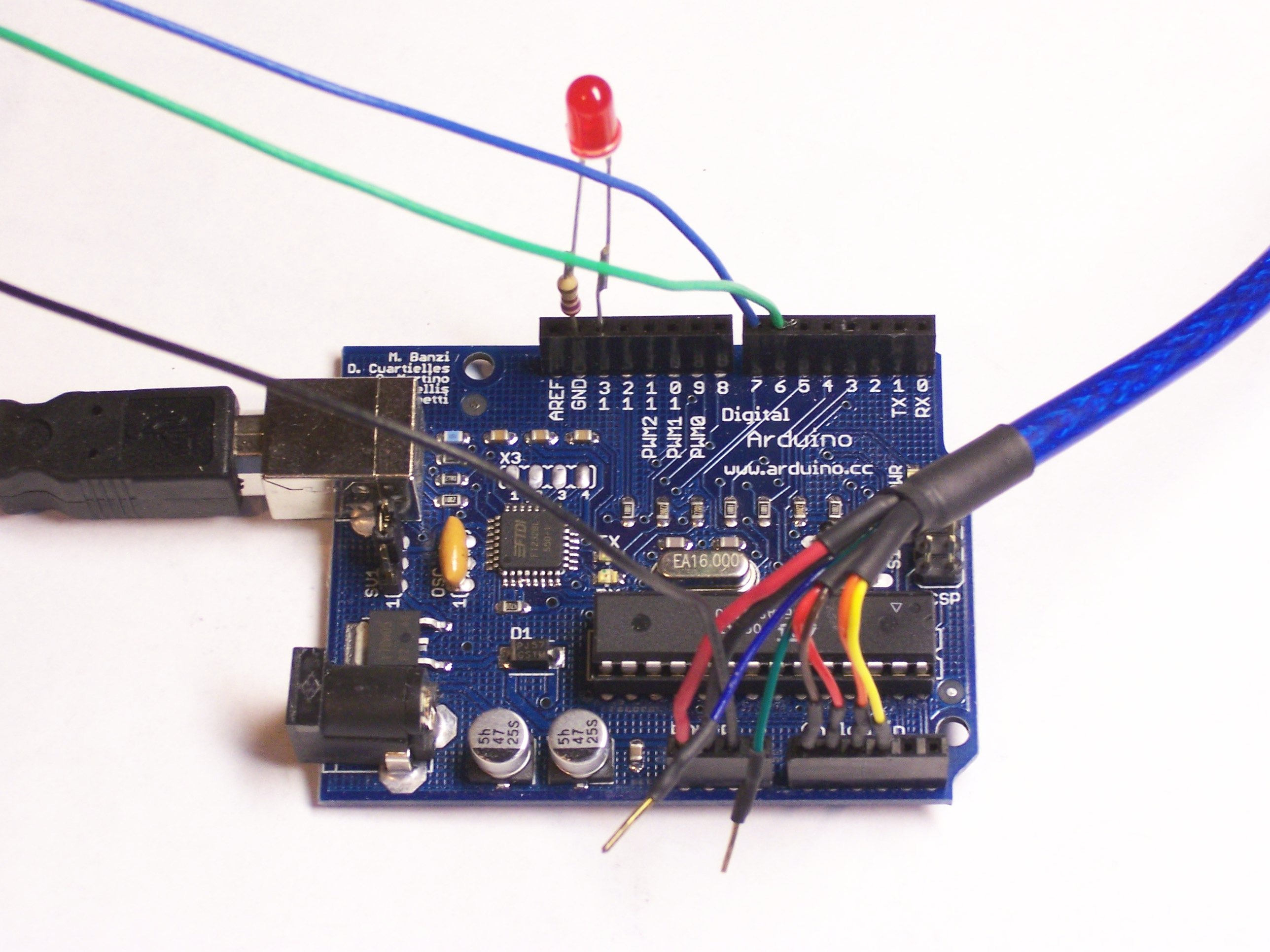
I have ribbon cables connecting it to the Arduino for power, LED output, and tilt input. The LED driver works perfectly, and (miraculously) the accelerometer works now that I’ve reoriented it. And that means I’ve been able to start writing code.
This isn’t much yet — it only detects whether the tilt is inner or outer, and which quadrant it’s in — but I think it gives a flavor of things to come.