I’m starting to gather parts to prototype the blue LED clock.
LED Drivers
I ordered four samples of the Allegro Microdevices A6276 constant current 16-LED driver chip that I want to use to run the display. I didn’t care whether I got traditional or lead-free; but due to availability and the way their sample fulfillment process works, they’ve sent me four lead-free and will send me four traditional when they restock their samples. Cool.
LEDs
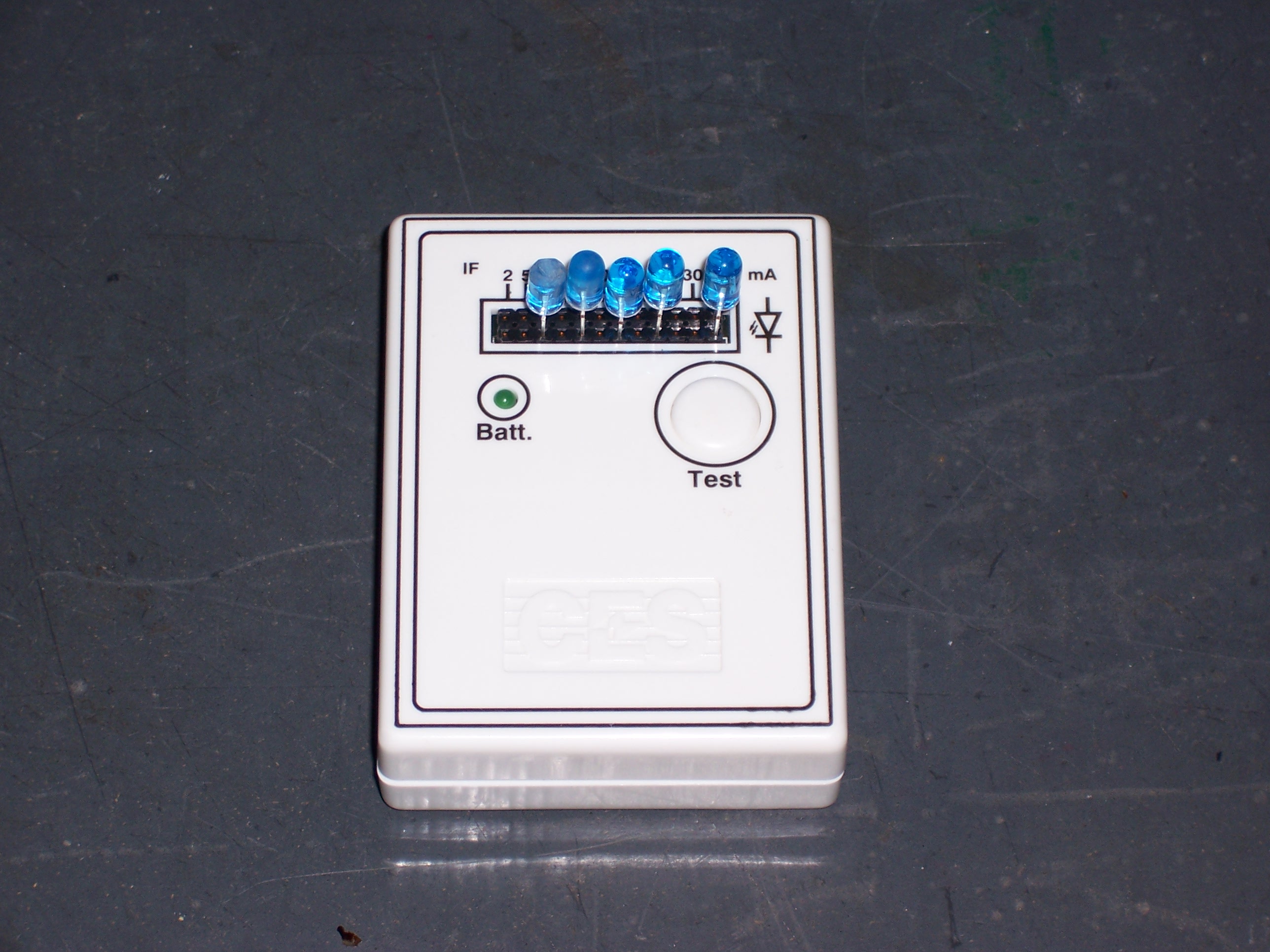
I’ve purchased 500 blue LEDs (10,000 mcd) on eBay from Best Hong Kong for $50.35 with free shipping and free resistors.
I haven’t figured out their pricing scheme, other than arbitrary. On their web site, these LEDs (AFAICT) are $.18 each, or $90 for 500; on eBay, they were $50, with a Best Offer option that suggests they’re willing to negotiate even further. That suggestion seems to be incorrect, though–they gave no response whatsoever to my two offers and my ask seller a question.
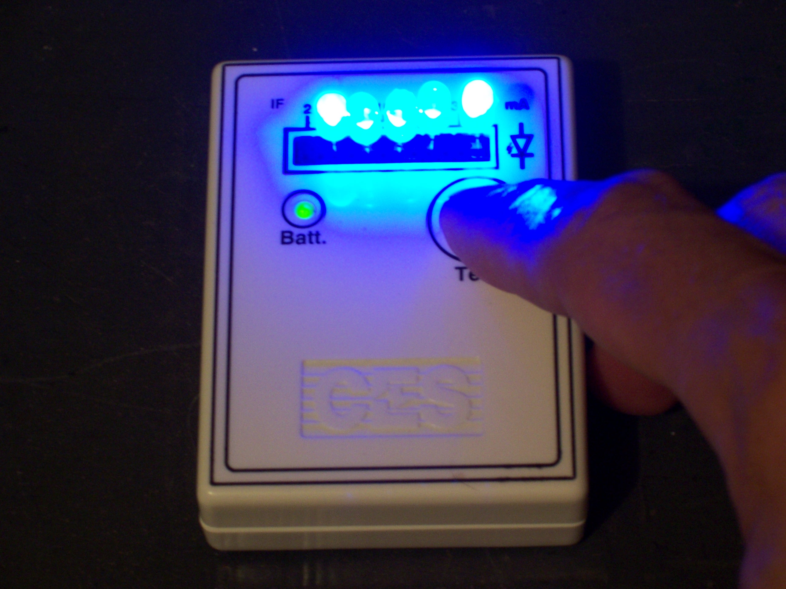
The LEDs have a 20° viewing angle, which is too narrow. Jeremy and I tested some of my Phillips LEDs, and they’re so directional we’re afraid we might not be able to see both ends of the clock from the same viewing position. However, I scuffed one up with 1500-grit sandpaper, and it looked fantastic–a very uniform brightness from a wide range of viewing angles. Yes, it’d be nice to just buy frosted ones, but I can’t find them in the quantity I need for anywhere near the price. I expect I’ll dedicate a buffing wheel to being a scuffing wheel when the LEDs arrive.
Timekeeping
I had several hours to myself in the car in the last couple of days, and did some thinking about timekeeping and battery backup. As much as I’d enjoy programming timekeeping functionality in the LogoChip, I shudder to think of dealing with backup during power loss.
I could take a reference timekeeping source from the 60Hz line supply like consumer alarm clocks, but then I’d have to switch to the internal oscillator for timekeeping when the clock was unplugged. To do that with any more accuracy than my alarm clock, I should compare the oscillator to the line frequency during normal operation and record the actual number of oscillator cycles per period. Add in dealing with battery changes–and do you have to recalibrate from scratch if you do lose all power? Or add a 1-bit NVRAM chip to the design? All of that’s doable, but ecchhh. I’ve started thinking about using an external real-time clock (RTC).
I have an old Dallas NVRAM/timekeeper DIP (probably lots of them, actually), which provided RTC functionality for 8088-vintage computers. Unfortunately, it’s made to work with a microprocessor and has 8-bit and wider address and data buses, registers, etc. Way too many pins to work with a small microcontroller, when I already have other pins to deal with to drive the LEDs.
Google on “real time clock” integrated circuit led me via Wikipedia to Maxim/Dallas. I feel like I’m starting to get a clue about browsing manufacturer’s offerings–after looking up their 1309, I visited related products and found the DS1340 I2C RTC with integral trickle controller to recharge the backup battery, and the DS1302 RTC with trickle-charge and a simple three-wire serial interface. I ordered samples of the DS1340C SOIC with internal 32KHz crystal, the DS1302 DIP, and (bless Maxim!) the external crystal for the 1302.