Archive for December, 2007

Disappointing Robo-Bug

Tuesday, December 11th, 2007

I went to Radio Shack yesterday for some patch cords and discovered three 3′ MIDI cables for $13. Score! Bought ‘em.

At the checkout counter, they have these cute little motorized bugs for $10.

Hexbug in plastic case

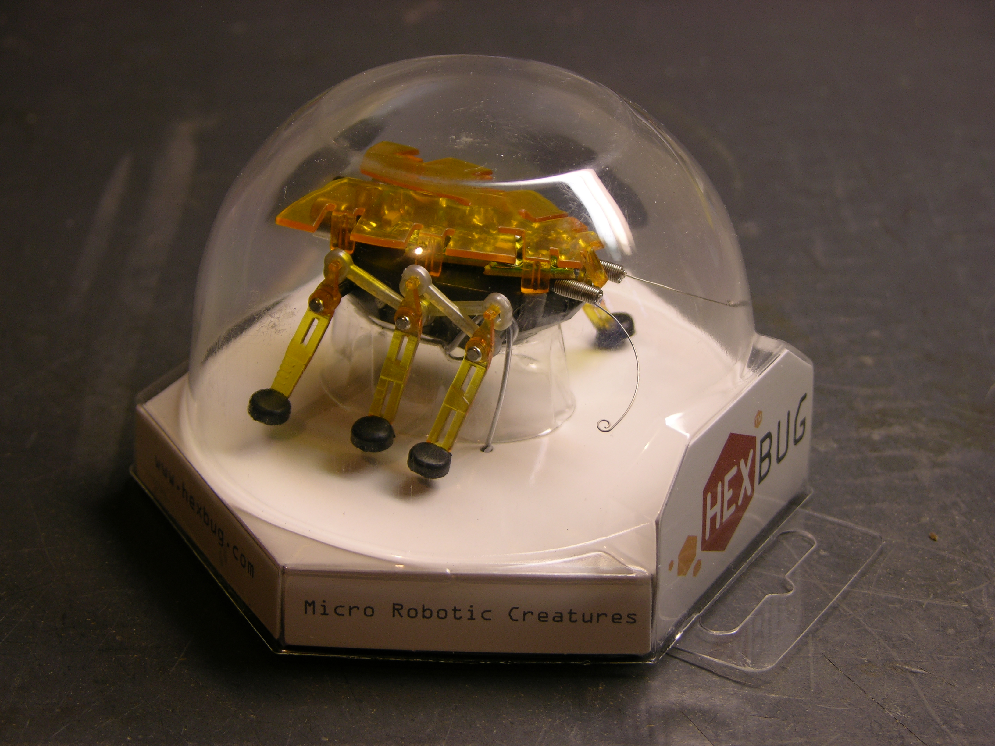
I was afraid it’d be lame; but I played with it a bit. When its feelers hit something, it backs up and turns. It sure looked like two motors were being used to control the forward / reverse-turn behavior. Turns out I’m the one who’s lame for getting fooled; but we’ll get to that.

$10 was about my threshold for a bug with two motors and two touch-sensitive antennae. It’d take some tricky rewiring or maybe making a new circuit board, but it should be possible to make the bug a lot smarter. Plus I didn’t really care about the microphone and response to loud noise, and I figured that accounted for a lot of the circuit board, which I could disable or remove.

Plus it’s really compact. The body is only an inch wide and about an inch and three-quarters long; that makes it really cute.

Bought one. Took it apart today.

Pre-Operative Impressions

Hexbug standing

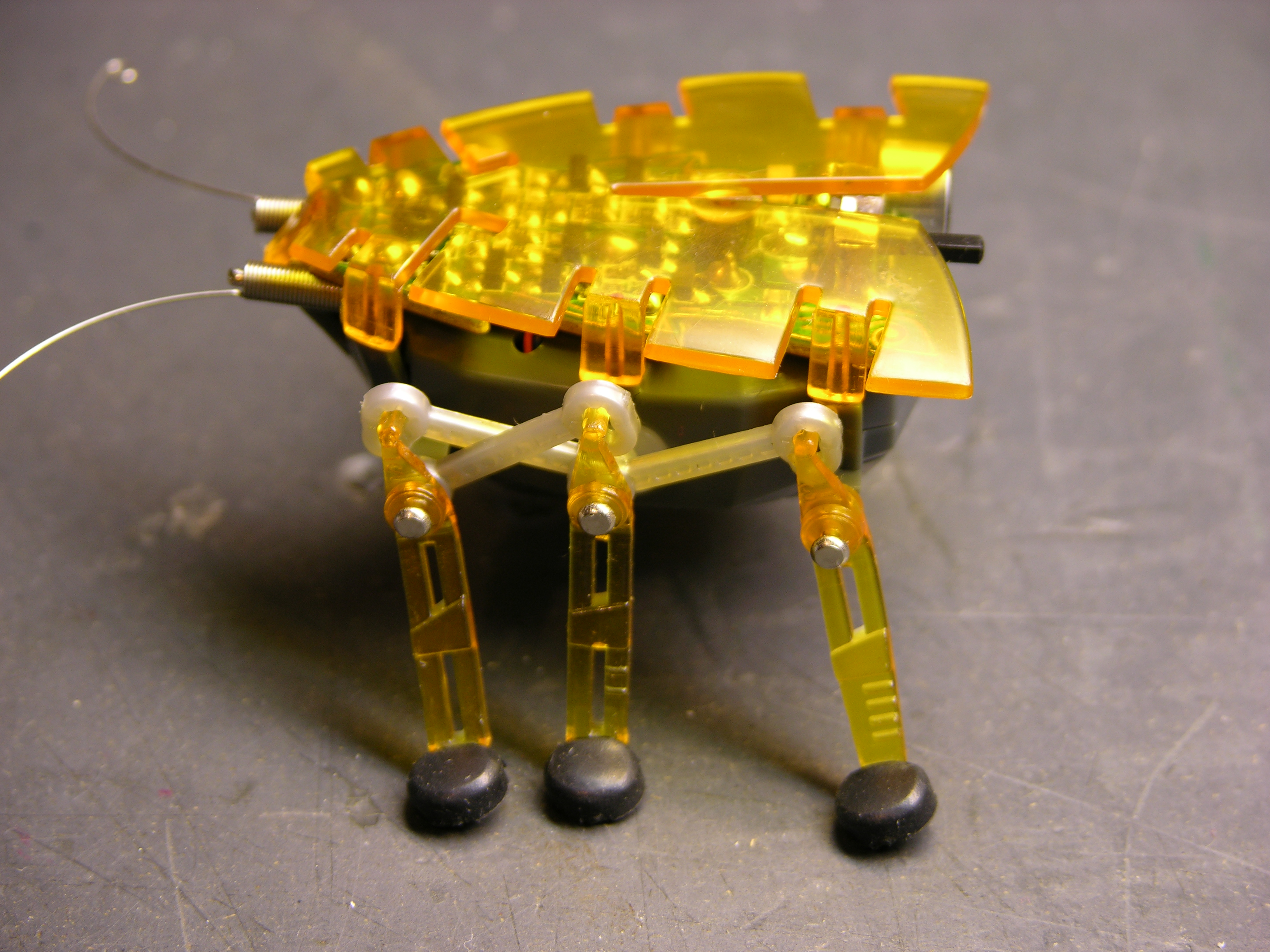
The Hexbug is what I call a faux walker — it doesn’t shift its balance to place its center of mass over alternating feet, and each side’s legs only have a single degree of freedom. It’s incapable of falling over, and it could just as well have treads or wheels. It’s still cute — I’m just being clear that I have no delusions about its level of sophistication. Except how many motors it has.

Each side’s legs are powered by a single rotating shaft, shown below. The linkages in the picture above transfer that motion. The front and rear legs move in sync, and the middle leg moves in the same direction but 180° out of phase.

Hexbug motor and linkage closeup

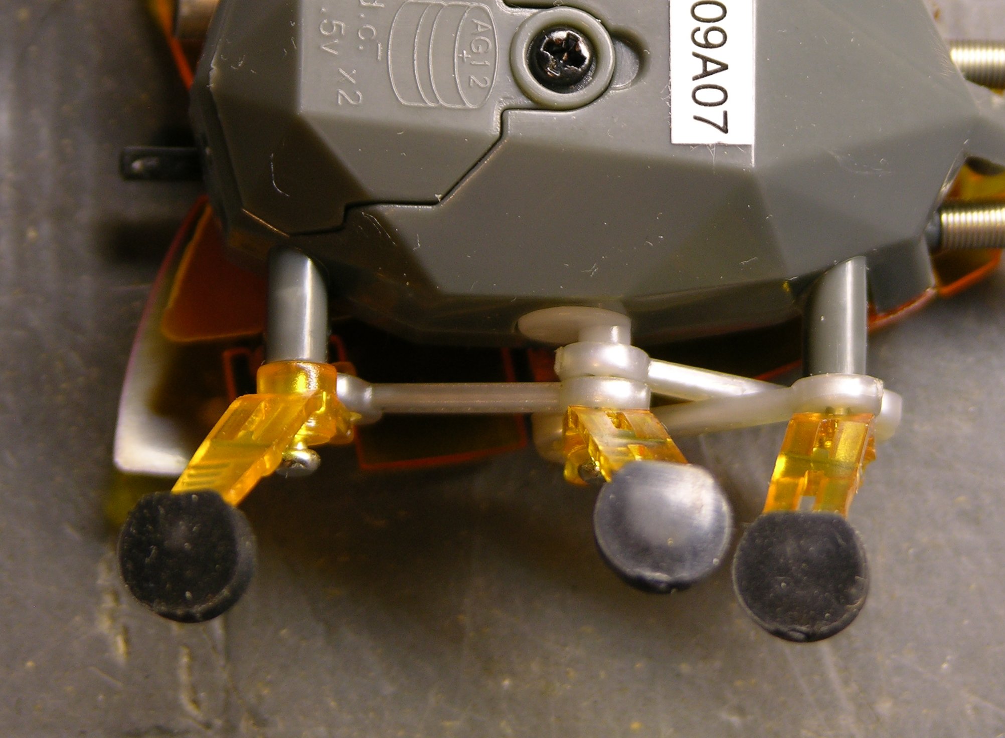
With the bug upside-down, you can see the rotating shaft coming out of the bug body, with an eccentric knob driving the linkages.

The outer legs’ axles are stationary, so the legs just swing back and forth. The middle leg’s axle is attached to the eccentric peg on the rotating shaft, causing the middle leg to move up and down while turning; this is how it lifts its foot to move without dragging.

Hexbug antennae closeup

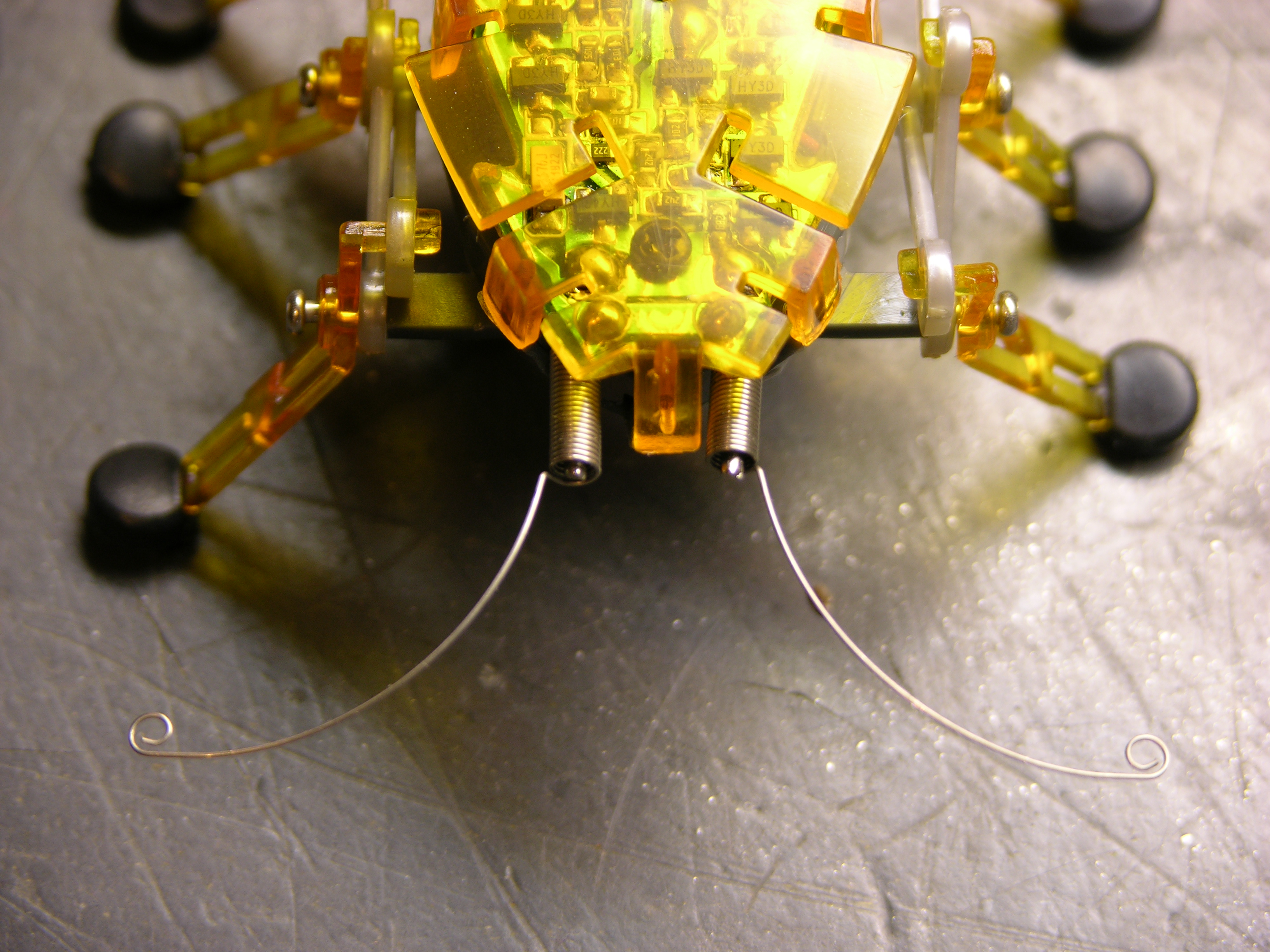
Finally, before beginning disassembly, the antennae are coiled springs positioned around stiff wire, with feelers protruding at the ends. When a feeler presses against something, the coil portion of the spring contacts the wire, closing a circuit and telling the bug to reverse and turn. These are actually more nicely done than other wire feelers I’ve seen — they do a really good job of retaining their shape and position.

Now to Operate . . .

Hexbug standing

The orange wing is press-fitted on, although more tightly than I expected. Each of the six side flaps that bend down, plus one on the front, continues in a peg pressed into a mating hole in the body. I put a flat screwdriver between the PCB and the wing and twisted to loosen each peg, being careful not to crush anything on the PCB in the process.

Hexbug PCB

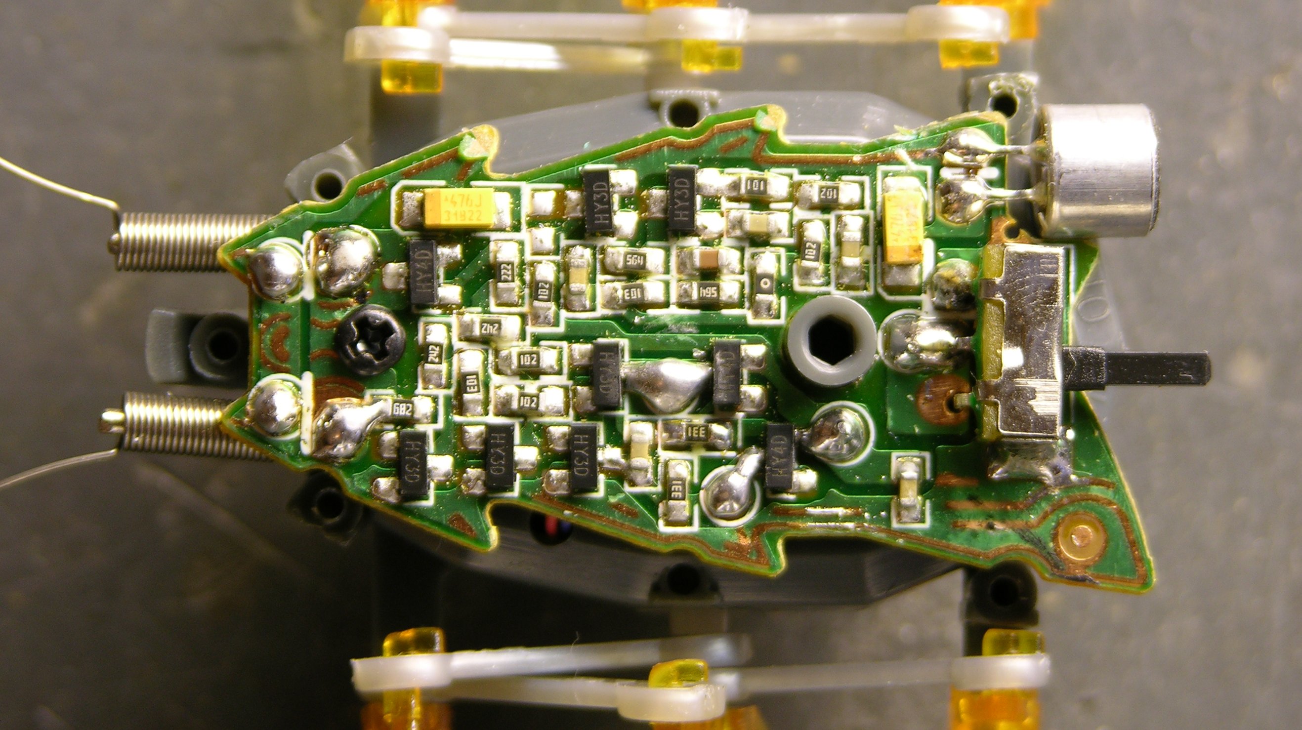
There’s the brain. I haven’t traced the circuit, but I can make a few observations. The solder blobs below and to the right of the grey standoff in the middle of the board are the battery connections, the blobs at the front are obviously the antennae connections, and the blobs in the center of the lower half of the board are the motor leads. Two leads. One motor.

The top of the board looks like it’s audio processing, running from the microphone in the back toward the antennae at the front (since a loud noise and an antenna hit perform the same function) and feeding into the motor drive on the lower half of the board.

Motor and Drivetrain

Removing the screw from the PCB and pressing in a latching tab at the back end of the bug (I did it with the batteries already removed, but this might not be necessary) allows the bug’s body to split open, revealing the motor and drivetrain. Motor. One motor.

Hexbug motor, geartrain, and reversing clutch

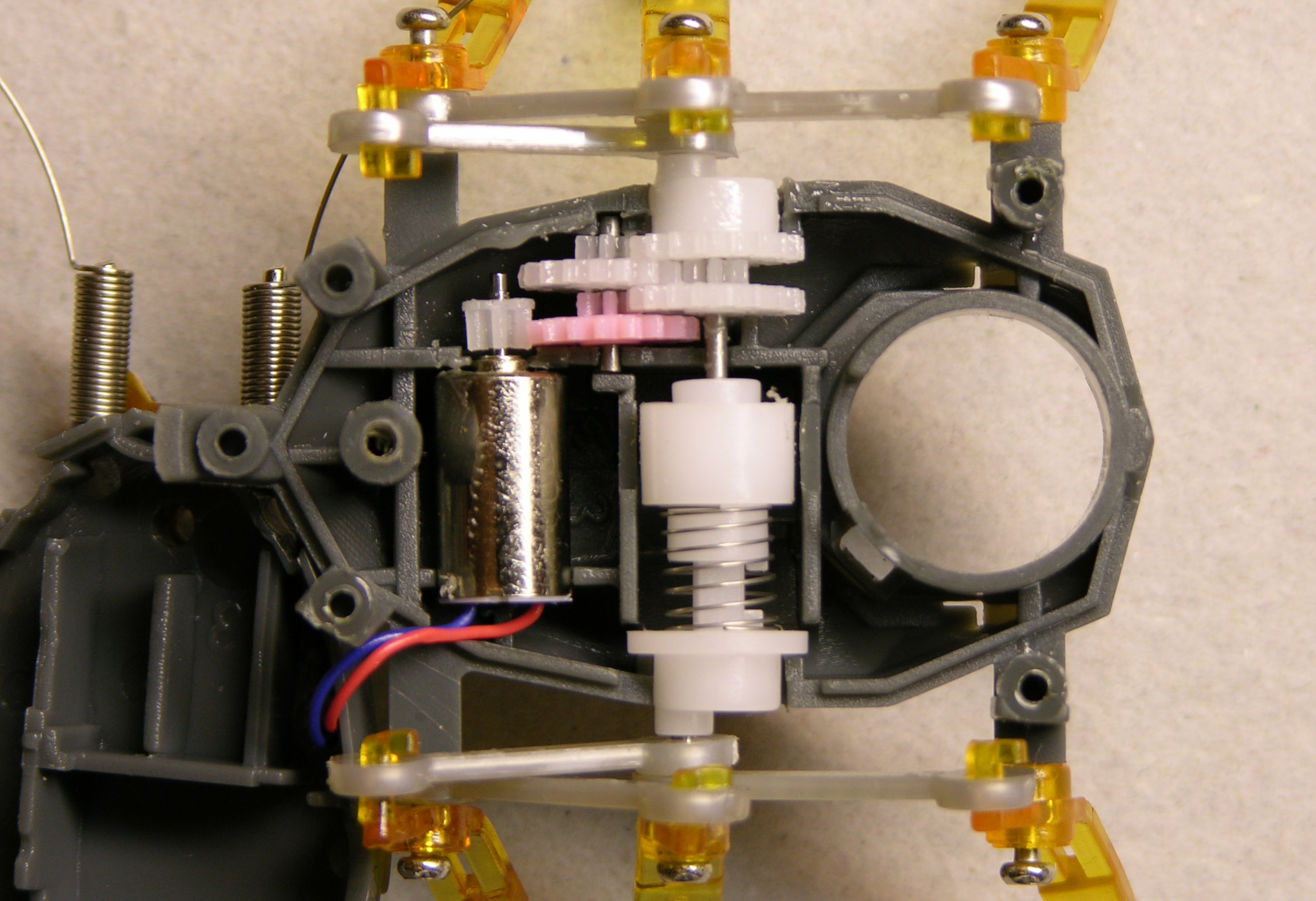
Look. It’s one motor.

Duh.

The motor leads aren’t very long, so the upper half of the bug is tucked under the front end of the lower half of the bug in this pic.

When the motor is turning “forward” and the white gear at the top of this picture (right-side legs) is moving with its upper teeth going forward, the coil spring at the center is being turned in the direction that makes it “unwind” and expand in length. This forces the cam at the bottom of this picture (left-side legs) to turn with.

When the white gear at the top is moving with its upper teeth going backward, the coil spring is being turned in the direction that winds it tighter, making it contract. This releases pressure against the bottom cam and causes the spring to slip against it instead of forcing the cam to turn.

What Next?

So now I don’t know what to do with this dumb bug.

  • Be a good little consumer and let it wander around my desk until its batteries die or it falls off and gets crushed. Not my style.
  • Mod it for two motors somehow — stick another motor in (hard!) or buy another bug, rip the left legs off both of them, glue their left sides together, and have a double-wide bug with two motors. But that’d require another $10 bug, and one $10 was the max I’d spend for a two-motor bug.
  • Figure out something else cool to do with it. Dunno what.

OR

  • Give it a smarter behavioral system that, within the capabilities of its lameness, emulates a two-motor bug.

The last one is actually kind of intriguing. Right now, when it hits an obstacle, it backs up enough to do about 90° of clockwise turn, regardless of which antenna made contact. So “reprogram” (rewire) the bug to discern which antenna was hit and turn 90° CW or 270° CW accordingly. Because it rotates about its left legs rather than its center, 270° CW is not the same as 90° CCW would be, but it’s as close as we can get.

With a tiny microcontroller on board, it could get more sophisticated yet, turning at other angles, and even doing quick reverses during normal forward travel in order to move in forward curves.

Thoughts?

Dissecting Swag

Tuesday, December 11th, 2007

At the end of October, I attended a national, annual conference on computing in higher education, and they always have a huge vendor expo with lots of swag being given away. These days, my interest really boils down to free t-shirts and what I refer to as LED trinkets (anything flashy); but a couple of other things turned out to be irresistible. So I brought them home and took them apart to see what makes them go.

USB Software Demo Fob

Orion, whoever they are and whatever they sell, snagged me as I was walking past and offered me this “demo on USB.”

Orion USB demo fob

I responded truthfully that I was fascinated . . . although I didn’t point out that I was fascinated merely by the idea of demo-on-USB, and really unfascinated by whoever they are and whatever they sell.

Orion USB demo fob PCB

Inside, the only components are LEDs and their current-limiting resistors, a pushbutton switch, and a Cypress CY7C63803 USB peripheral controller chip. From the datasheet, this thing is an 8-bit microcontroller with integrated USB support, in-system reprogrammability, and 14 (total, configurable) I/O pins in a 16-pin SOIC package.

It’s targeted for use in mice, keyboards, gaming peripherals, barcode scanners, etc., and it strikes me as a really slick little device. It’s available at Digi-Key in single quantities for about $1.45 — seems like there may be some kind of opportunity there, if the development system isn’t prohibitively expensive.

So . . . it seemed unlikely that an 8-bit microcontroller would have an entire software demo on it, which led me to question exactly what the dongle did. I assume it was made to demo on Windows; and even if I had a Windows machine, there’s no way I’d plug this thing in and get pwned.

Instead, I did what any self-respecting geek would do and hooked it to my Linux box, with tail -f /var/log/messages running.


Nov 4 18:17:06 dell2600 kernel: usb 4-2: new low speed USB device using uhci_hcd and address 10
Nov 4 18:17:06 dell2600 kernel: usb 4-2: configuration #1 chosen from 1 choice
Nov 4 18:17:06 dell2600 kernel: input: Cypress Semiconductor, Inc. enCoReII Keyboard RDK as /class/input/input9
Nov 4 18:17:06 dell2600 kernel: input: USB HID v1.11 Keyboard [Cypress Semiconductor, Inc. enCoReII Keyboard RDK] on usb-0000:00:1d.3-2
Nov 4 18:17:06 dell2600 kernel: input: Cypress Semiconductor, Inc. enCoReII Keyboard RDK as /class/input/input10
Nov 4 18:17:06 dell2600 kernel: input: USB HID v1.11 Device [Cypress Semiconductor, Inc. enCoReII Keyboard RDK] on usb-0000:00:1d.3-2

It was automatically detected as a keyboard-class device. Okay. And its little blue LEDs were glowing, glowing, hypnotizing me, luring me . . . press the button . . . it can’t be that bad . . . press the button . . .

rwww.orionondemand.com

Huh. Typed that right into my terminal, as if it were a keyboard.

Looks like it’s trying to go to a URL, but I don’t know what’s up with the “r” in front. I tried “keying” it into vi after hitting Ctrl-v to capture escape codes; I redirected it into od -c as well. Nothing. Just the “r.”

I have to assume on Windows, it does something else — that there’s a keycode my Linux doesn’t recognize that starts up the default browser, or that there’s additional USB functionality sending through another driver that Linux doesn’t support by default. But how it works, in general, is now easy enough to see.

Solar-Powered Flashy LCD Shutter Thingum

LCD swag, light

I didn’t even see these at the show, but after we got back, my boss gave me his.

LCD swag, dark

It’s apparently a picture holder; but in the lower right corner, there’s a little sign that flashes on and off every couple of seconds saying “Confirmed.” (I have yet to figure out what is confirmed, but maybe it’s part of the vendor’s current marketing campaign. Brilliant, that, if you can’t associate the keyword with the company without having seen their literature first.)

My first impression was that there was an EL backlight going on and off. But the glass looked like an LCD . . . and why would they put in a whole color LCD just to display a static graphic saying “Confirmed???” It turns out there’s no backlight, and the LCD is being used as a shutter to hide and reveal a paper graphic.

LCD swag circuit board

Here’s what it looks like after prising it out of the frame and opening the clear plastic case. The circuit board has two transistors, and the power source is a narrow strip solar cell hidden along the lower edge of the enclosure.

LCD swag circuit board and solar panel

It occurred to me that perhaps the solar cell could be part of the timer oscillator — when light shines through the LCD, the cell builds up enough charge on a capacitor to darken the LCD, which in turn discharges the capacitor and restarting the cycle. Not so, as far as I can tell; the LCD continues flashing with the solar cell out of the case and exposed directly to continuous bright light.

Rather, I assume that the circuit is a simple two-transistor oscillator . . . and that’s about as far as I care to take my analysis. The PCB’s pretty intelligible if anyone wants to trace it out, but I already know enough to satisfy my curiosity: solar cell rather than battery, and LCD shutter rather than backlight.

Treasures from Slim

Tuesday, December 11th, 2007

An ice storm was predicted for today; and in anticipation, the university shut down. Even faculty and staff don’t go in for a full shutdown.

Icy trees on my street in North Newton

Temperatures must have been quite a bit higher than expected; because although there’s some ice on trees, all the freezing rain that hit the ground stayed wet and is draining away.

Icy tree looming over garage

So here I am at home, waiting for more limbs from my neighbors’ tree to fall on my garage, and catching up on some electronics.

Another Weekend of Cleanup

Cort and I went to Pittsburg this past weekend to help Maeve clean up more of Slim’s stuff. The focus this time turned out to be books, but we each plundered other areas as well.

Ohmite resistor cases

I adore these vintage resistor storage cases. The drawers are about 1/2″ high — you don’t need much more than that to store resistors — and they’re totally dreamy. (Um, yup, I’m a geek. :-) )

Engler Hour Meter

Cort and I found this on a shelf in Slim’s garage:

Engler hour meter, angle view

It’s an Engler Instrument Company hour meter model 10N, and I think it’s absolutely gorgeous.

Engler hour meter, face

It wants to be built into a rich walnut case for something. (I’m not an active steampunker, but I definitely admire real and faux antique gear with wood and brass and glass and gleaming chrome and flicking needles with paper scales behind them.)

Engler hour meter, back

Give it 110VAC and it counts hours. The case is riveted shut, so there’s no resetting it. Still, it wouldn’t be that hard to run it long enough to reset — only about 35 months. (I’m going to need a good reason to do that, though . . .)

Slim’s Microcontroller Development Drawer

Slim's microcontroller development drawer

I’m not sure which cabinet this came from, but Maeve had taken a whole drawer full of Slim’s microcomputer and microcontroller development gear out to the garage. Cort and I picked through it, boxed it all up, and brought it home.

Some of the detail that follows is as much an inventory for Cort and me so we know what we have and where it’s packed, as it is intended to be of general interest.

PIC sticks

Lots and lots of microcontrollers and related chips: Two sticks of TL064 op-amps, three sticks of PIC16C55s, three of PIC16C56es, two of PIC16C57s and two UV EPROMable chips, two sticks of PIC16C71s, a stick of ISD 4004-16MP 16-minute audio recording chips, a stick of ADCs, a bunch of miscellaneous Mozer Digitalker chips, an XC68HC705K15, and a couple of MC68HC811E2INs.

Circuit Cellar RTC52 and RTCIO kits

Circuit Cellar RTC52 and RTCIO kits, unassembled. I was never a subscriber, but these appear to have been the foundation of many Circuit Cellar control and automation projects; see for example this touch-tone remote-controllable home automation system from 1991.

PICBASIC development kit

A PICBASIC development kit.

Microcontroller development boards

Various microcontroller development boards, at least two of each, and heavily biased toward Motorola.

M68HC705KICS development board

An M68HC705KICS programming board, adorably fitted in a box with cutouts for the power leads and ribbon cable, so it never has to leave its nest.

SWTPC boards

A RAM board and two MP-09A CPU boards from a Southwest Technical Products Corporation 6800/6809 computer, circa 1978. I would really like to find a good home for these with a SWTPC collector. I think there’s a related chassis in storage as well, which I’ll dig out next time.

LCD screens

Couple of LCD screens in “widescreen” format. :-)

Speech synthesizer board

A very funky, battery-powered speed synthesizer board. Cort said Slim picked this up somewhere (probably at the Dayton Hamvention) and the two of them (particularly Cort) poked at it for a long time figuring it out. They were able to get it to make noise, and it has both recorded phrases and a phoneme generator, but they never found any documentation about the dictionary and weren’t willing to spend the time to catalog it by trying every address. Cort also said it draws half an amp.

Huge pushbutton switch

And a very large, datacenter-style pushbutton switch. Sweet!

Garrett’s Wife’s PC Stopped Working

Thursday, December 6th, 2007

Damaged CPU

LED Puck Design Questions

Saturday, December 1st, 2007

Cost: Realistically, I see this thing climbing into the $15-30 range for materials. That’s more than I’d pay to buy a puck from ThinkGeek, but not more than I’d pay to construct one myself that I helped design. Anyone else?

Battery: Seems like we’d get a lot better power density (translating to smaller size and longer runtimes) if we used an RC-style LiPo battery, I’m thinking about the size of a matchbook or so. This’ll be more expensive; but I’m concerned that fitting in 2-3 AAA or AA cells will make the puck bulky that it’s not cool anymore. How do you feel about having to buy a special battery for it?

Charge circuit: I can find a charge-control chip and use the datasheet’s sample implementation as well as the next guy; but that’s really just a starting point, and I understand there are often subtleties involved in getting the best real-world performance. Does anyone have a lot of charging circuit design experience, or know someone who does, who’d be willing to design that portion and contribute it to an open-source hardware, community-developed project? We might want to look at LadyAda’s WaveBubble or the Chumby design for reference.

Voltage-boost circuit: Depending on what battery, microcontroller, and LEDs are used, we may need to boost the battery voltage. Same questions as on the charge circuit.

Surface-mount components: I don’t think there’s room to use through-hole technology. I’m envisioning at least the microcontroller, LED driver, and optional real-time clock chips being SMT. LEDs need to be through-hole, in my opinion, both for rated brightness and so they can be aimed slightly away from the center for better light dispersion. Will a few SMT components be enough to keep anyone from building this who would otherwise be interested?

Enclosure: My first thought was pouring this thing in resin, but I’d really like to be able to take it apart and service / enhance it. I’m now leaning toward a two-piece milled enclosure (probably lexan) that would sandwich the PCB edges in rubber for shock control and hold together with recessed screws underneath. Add an appropriate O-ring and the whole thing could probably be made watertight — which in my book counts as another feature. :-) Thoughts?