LED Clock: 498 LEDs

July 1st, 2006 by Keith Neufeld

Package from Hong Kong

My LEDs arrived last weekend. Here’s how you ship 498 LEDs and 100 of the wrong resistors from Hong Kong:

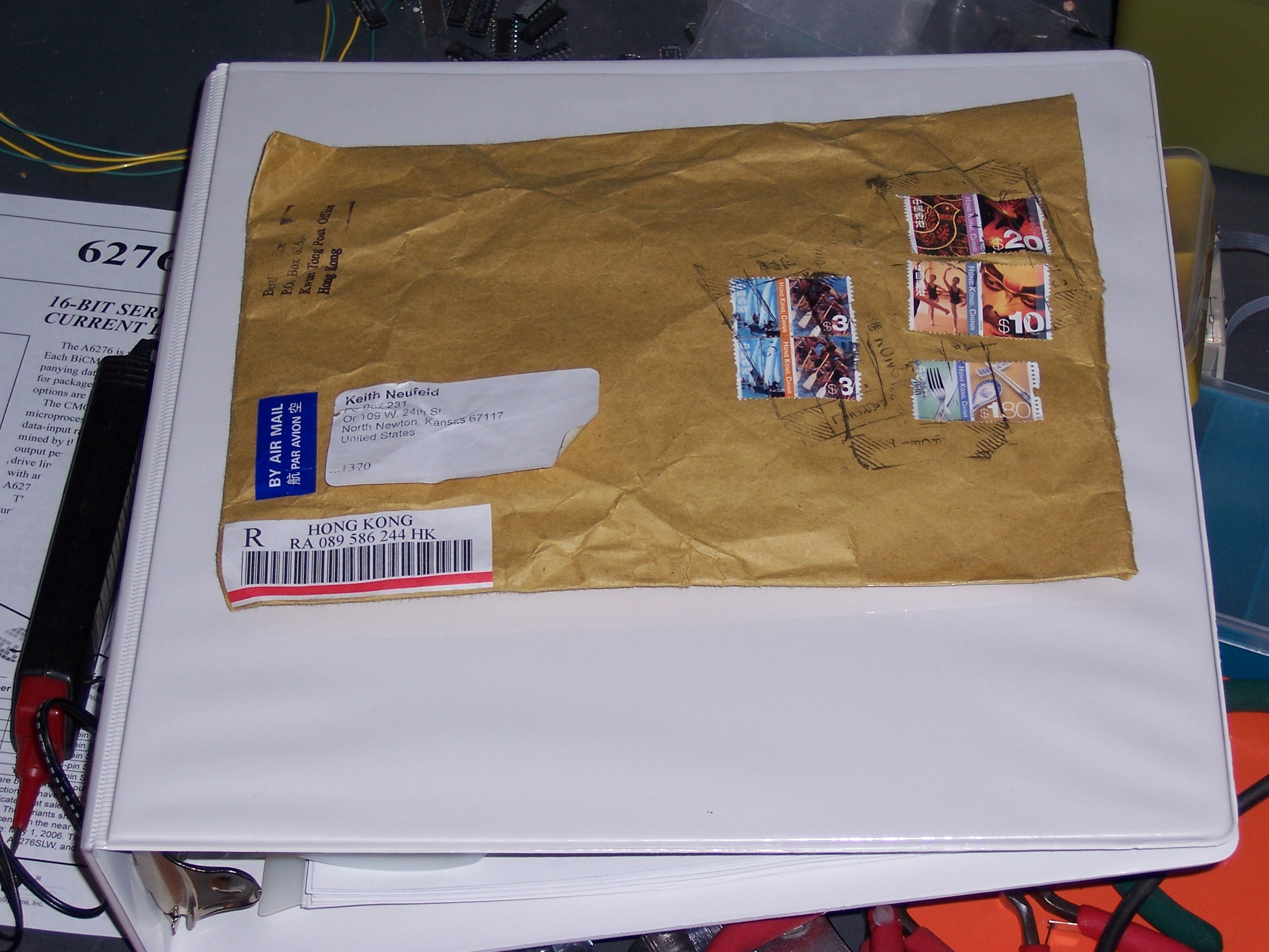
Yes, 498. Of course I counted them. Best Hong Kong has a reputation for great prices and terrible customer service, so I was curious how much they were going to mess up my order. A little bit and then some, as it turns out.

By the way, here’s how to count more than a couple dozen small objects. Get a container to use as a discard pile, then count “3-6-9″ into the discard, “10″ into a new holding pile. “3-6-9″ discard, “10″ holding, etc., until you have few enough left that they don’t make 10. Move that remainder to the ones place of your answer row.

Now count your holding pile, each object of which represents 10 original objects. “3-6-9″ into the discard, “10″ into a new holding pile. When you have less than 10 left, that’s the tens place of your answer row. Repeat for 100s, 1000s, etc. as needed. When you’re done, read off the answer by counting the objects in the different places in the answer row.

It’s really efficient to do, for several reasons. First, three is about the largest number of objects that most people can cluster quickly and with absolute certainty, so you’re going through the objects as quickly as possible without actually counting. Second, that last part is important–because you’re not counting, there’s never anything to remember (other than 3-6-9), and it’s virtually impossible to lose your place. Finally and related, you use the objects themselves as placeholders to store and remember your result.

4, 9, 8. Not quite 500, but close enough that I can forgive them.
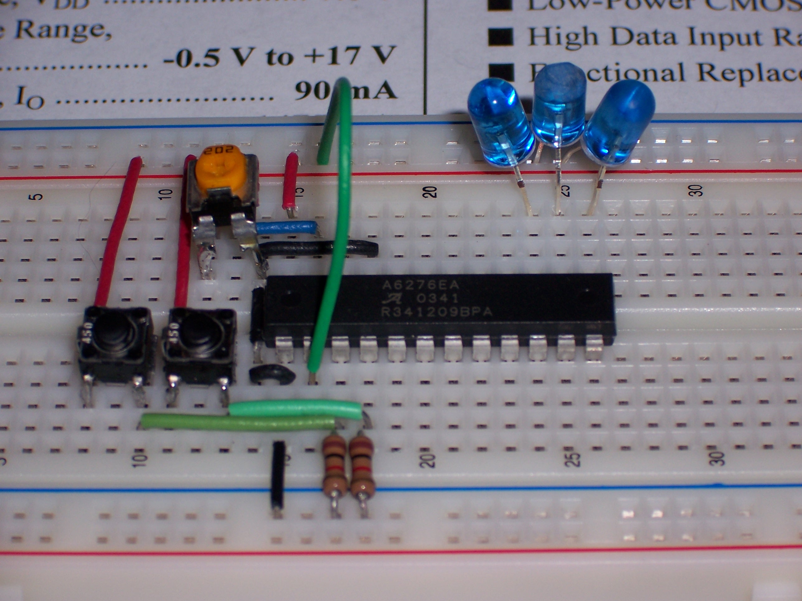
Wrong Resistors

The resistors, however, are another matter. Best Hong Kong explicitly advertised free resistors on this auction, and their instructions explicitly said to specify my choice of resistor value as a comment during checkout. I did so–I added this note to my PayPal checkout:

If you have ’1000-ohm’ resistors, please make all of my free resistors ’1000-ohm’.

If you don’t have ’1000-ohm’ resistors, please make my resistors ’220-ohm’.

Thank you!

They sent 470Ω resistors–their recommendation to use with blue LEDs on 12V automotive systems. Not acceptable. I want my 1K resistors to use for miscellaneous projects, or my 220Ω resistors to use with LEDs.

Monday morning, I sent an email directly to Best Hong Kong explaining the situation:

Subject: Received item #7605792211 but wrong resistors
To: ***@BESTHONGKONG.COM (KEN)
Date: Tue, 27 Jun 2006 10:28:53 -0500 (CDT)

Yesterday I received my shipment of 500 XtraBright 5mm 10000mcd+ F/S F/R
LEDs, eBay item number 7605792211. However, the free resistors weren’t
right: I received 470ohm resistors instead of either 1Kohm or 220ohm
resistors like I requested in my PayPal checkout:

> Amount: $51.35 USD
>
> Transaction ID: 8Y445643T3613431N
>
> Subject: Blue LED Set of 500 XtraBright 5mm 10000mcd+ F/S F/R
>
> Note:
> If you have ’1000-ohm’ resistors, please make all of my free resistors
> ’1000-ohm’.
>
> If you don’t have ’1000-ohm’ resistors, please make my resistors
> ’220-ohm’.
>
> Thank you!

Since the auction advertised my choice of resistors, I think you owe me
a set of 1Kohm or 220ohm resistors as I requested. Are you the right
person to contact? What can we do to work this out?

I got no response. Wednesday I submitted the same message through eBay, and haven’t received a response. I just opened a dispute through eBay and PayPal, sending this message:

After purchasing my LEDs on eBay, I followed your instructions to select my free resistors, and specified my choice of resistors as a note on my PayPal payment. I requested that the resistors be 1000-ohm resistors if possible, or 220-ohm resistors (which you listed as an option on the auction page) if you couldn’t provide 1000-ohm resistors.

I received my LEDs and they appear to be fine, but the resistors that were shipped were 470-ohm resistors–not what I asked for.

Since your auction posting offers for me to specify my choice of free resistors, and I followed your instructions to do so, I think you owe me the 1000-ohm or 220-ohm resistors that I requested.

I’m sorry to have to open a dispute through eBay and PayPal, but you haven’t responsed to the email I sent five days ago and the email I sent through eBay three days ago.

We’ll see what happens.

Meta: Upgraded WordPress

June 30th, 2006 by Keith Neufeld

I’ve upgraded my WordPress blogging software from version 1.5 to 2.0.3. I’m seeing a lot of changes behind the scenes, but not much in the up-front display. If you notice anything that doesn’t seem to be working right, just add a comment to this post and I’ll look into it.

I’m trying to find a way to remove all of the sub-pages (Roomba, PowerBook, etc.) from the sidebar, so they don’t clutter up every view but you can still access them from their master index page. It looks like there may be a way to do it with page templates and customizing the theme, but GAAAAHH!!! Surely someone else has done it by now???

Follow-up:

I’ve found Daniel Schindler’s Exclude Pages plugin, which lets me enter the IDs of pages to exclude from the list.  It’s clumsy and I’d much prefer something that has a flag on the page’s own editing screen–but it works, and that’s enough for now.

LED Clock: List of Posts

June 30th, 2006 by Keith Neufeld

Yesterday I created a page with a list of all the posts about the LED clock in one place.

LED Clock: Daylight Savings Time

June 25th, 2006 by Keith Neufeld

I hadn’t even considered DST until just now, when I dug out my “eBay special” logic analyzer to see if I could figure out how it works, and noticed that its clock is an hour off.

The timekeeping chips I’m considering don’t (as far as I know) have any facility for DST. However, they do record month, day, and day of week. If I can find the specification for when DST starts and ends, I should be able to increment the hour by 1 during DST, and use the straight hour value during DWT. I’m talking about translating in the display software–I don’t want to monkey with the actual time setting on the RTC if I don’t have to.

Since the clock won’t display the date (at least as currently envisioned), the translation is pretty easy–literally just add 1 to the hour, without worrying about a carry to the day and month fields.

LED Clock: Numbering Order Reanimated

June 24th, 2006 by Keith Neufeld

This is it.

And by “it,” I mean both the revised image, and the way it’s gonna be.

How Jeremy Animated

Paintshop. Take your original image (layer 1), add a background solid black (layer 0) (you can’t see this layer, because your layer 1 diagram covers it up), copy bright looking light from another file, paste it in on a new layer (layer 2) in LED position one, make layer 1 invisible, save file to JPG (flattens image to visible layers), make layer 1 visible, move pasted image to position two, make layer 1 invisible, save file, rinse, repeat. Then reconstruct the JPGs into an animated GIF in Ulead. All I had to do for this new one was change the order of the JPGs.

LED Clock: Numbering Order Animated!

June 23rd, 2006 by Keith Neufeld

Jeremy rose to the challenge and animated the LED sequences I put together. Here they are, the way I laid out the diagram, and again with a black background the way they’d appear behind a smoked bezel.

And that’s exactly what I needed to see. I don’t like the look of the first 2-3 LEDs popping around the corner–it looks clumsy to me. I’d like to see it again, starting with the one I had second, and picking up the first one on downstroke. That is, start with the middle left, up and around the top loop, left-left-down-left through the midde, and down and around the lower loop.

Of course, that means completely redoing the entire schematic and PCB that I finished today . . .

Jeremy? ‘Nother animation, please?

LED Clock: LED Numbering Order

June 22nd, 2006 by Keith Neufeld

The Question

This totally doesn’t matter, and OTOH it’s a little aesthetic touch I want to get right. What should be the order that the individual LEDs are numbered within one character?

This impacts two things: circuit layout and LED test patterns. I’m ready to start laying out the circuit, which is why I’m thinking about it now. I’ve thought about LED test patterns, which is why I’m thinking about it at all.

The LED drivers shift in their data bit by bit, while shifting their current contents out in the same fashion. So if you want to enter 11111111 into a driver currently containing 00000000, it works like this:

00000000 ← 11111111
00000001 ← 1111111
00000011 ← 111111
00000111 ← 11111
00001111 ← 1111
00011111 ← 111
00111111 ← 11
01111111 ← 1
11111111

The Impact

This means it’s very easy to do moving marquee type of effects by shifting a single 1 bit or a short row of 1 bits through a display:

0000000000000000
0000000000000001
0000000000000011
0000000000000111
0000000000001110
0000000000011100
0000000000111000
0000000001110000

Just shift a few 1 bits into the register, then keep clocking it and latching the input register to the output register on every clock cycle.

Now, granted, the 6276 is so fast compared to human vision that I could shift in an entirely new pattern from scratch, then latch it, way faster than you could possibly see. But there’s a certain elegance in taking advantage of the driver’s architecture for the design of a test pattern. So I’d like to arrange the LEDs to do just that–make a pleasing test pattern when activated in order from D0 through D30. (Not a typo–only 31 LEDs in the design.)

The Proposal

Here’s what I’ve come up with, drawn a couple of different ways:

LED Order LED Order

The test pattern starts in the middle of the digit, loops through the upper half clockwise and the lower half counterclockwise, springs off the right edge to the top of the colon, and drops down into the period. The possible issues are:

  • Is this even the right kind of pattern to do?
  • Is that the right starting point, in particular with respect to the extra LED inserted in the lower half to smooth out the 2?
  • Is it right to skip the middle-right LED on the way down, and leave it for the end before jumping up to the colon? Or should it be included on the way down, and skipped on the way to the colon?

I’m open to suggestion, but I’m also afraid that it’ll be hard to evaluate the visual smoothness of the effect for sure until a digit is prototyped–and I can’t prototype on a breadboard; it’ll require a custom PC board to do it. I guess if I were sharp enough with computer animation, it shouldn’t be that hard to do this in software; but at this point, I’m not sure I’m up to it. Maybe I should pull out my old C-64 . . .

LED Clock: Enough Controller Pins?

June 21st, 2006 by Keith Neufeld

Last night, while programming the LogoChip A6276 interface, I started to become concerned about having enough LogoChip pins to connect to everything I want to wire up to make the clock work. So I just did a quick sanity check to see whether I’ll have enough pins, or whether I need to double up digits together.

Here are the LogoChip pins:

Available Pins
A0 – A2
A3 – A5 ?
B0 – B7
C2
C6 – C7

I’m not sure whether A3 – A5 are available or not. They’re ghosted (grey) on the LogoChip sticker, and I’m not sure why. But because of that, I think I didn’t provide sockets for them on my Curiously Strong LogoChip, which may pose challenges while prototyping. Additionally, A0 – A2 didn’t work for driving the 6276, so maybe not even all of the available pins will work.

Anyway, here’s a tentative pin assignment.

Chip Lines Count Possible LogoChip Lines
A6276 LED driver serial data in
clock
latch (each character)
2
.
6-8
A0 – A1 (didn’t work)
   or B0 – B1
B0/2 – B8
Dallas clock chip data
clock
enable?
2-3 A0 – A2 (didn’t work for A6276)
PC serial port? TD
RD
2 C6 – C7

[Ewww, I don't like what the WordPress stylesheet does to the table text alignment.]

Looks like everything should work out, assuming that I can use all the pins the way I intended. In fact, if the clock is only six digits, I can use B0 – B1 for the 6276 data and clock lines and B2 – B7 for the digits’ latch lines, fitting the entire display driver into one I/O port. Tidy.

The Dallas timekeeping chip will need either two or three pins, depending on whether I use the DS1340 with I2C or the DS1302 with “simple” three-wire interface.

The LogoChip already connects to the PC’s serial port on pins C4 and C5; however, receiving data halts a running program. That means that while uploading control data to the LogoChip, although the real-time clock chip would continue to keep time, the display would freeze and stop updating; and that every data transmission would need to be followed by a command to restart the display program.

Since I may want to be able to send updates to the LogoChip while it’s operating (time corrections, commands to change display mode, etc.), I’m thinking of using the PIC’s built-in UART on C6 and C7 for run-time serial communication.

Anyway, the bottom line is that as long as I can figure out how to use the A port lines for digital I/O, and as long as we’re only making a six-character clock (HH:MM:SS without .TH), there are enough lines. Good deal.

LED Clock: Programming the A6276 LED Driver

June 20th, 2006 by Keith Neufeld

Banging Bits

I got the LogoChip controlling the A6276 tonight. I programmed from the bottom up, writing code to bang the bits first, and ending up with . . . not much more than code to bang bits. It’s really pretty easy–put the bit on the line feeding the serial data input, strobe the clock line (active high), and when you’re ready strobe the latch line (also active high) to copy the data to the output register.

I started out using pins A0 – A2 for the control lines, and for some reason I still haven’t figured out, they didn’t work. I could set the data bit (A0) high; but every time I toggled the clock line (A1), the data line fell low again, preventing me from shifting a 1 into the input register. Huh?? When I moved the lines to B0 – B2, they worked fine without any other changes to the code. Huhuuuhhhh?????

Strobing Clock and Latch Lines

Given that the 6276 can shift data at 10Mhz, the LogoChip PIC is running on its internal 10MHz oscillator, each PIC operation takes at least one clock cycle, and each Logo instruction probably takes several PIC operations, I should be pretty safe toggling the clock and latch lines high on one instruction and low on the next without a delay in between. I did test with mwaits in between, but it really didn’t make any difference except to slow it down. I guess conceivably I could see problems when I’m trying to shift real data later, so I’ll keep it in mind.

The Code

Here’s what I ended up with:

  • a6276.txt – Program to control Allegro MicroSystems A6276 LED driver

Here’s the code:

;   a6276.txt
;
;   20-Jun-2006  Keith Neufeld
;
;   Drive an Allegro MicroSystems A6276 constant-current LED driver chip.
;   The chip takes three inputs:
;
;   A0  serial data in (SDI)
;   A1  clock (CK)
;   A2  latch enable (L)

;------------------------------------------------------------------------------
;   Debug system
;------------------------------------------------------------------------------

constants [[debug 0]]
;constants [[debug 1]]

;------------------------------------------------------------------------------
;   Section to manipulate A6276.
;------------------------------------------------------------------------------

constants [
    [a6276-sdi-port portb] [a6276-sdi-ddr portb-ddr] [a6276-sdi-bit 0]
    [a6276-ck-port portb] [a6276-ck-ddr portb-ddr] [a6276-ck-bit 1]
    [a6276-l-port portb] [a6276-l-ddr portb-ddr] [a6276-l-bit 2]
]

;   Push one bit into input register.
to a6276-bit :bit
    ;   Put bit on data input port.
    ifelse :bit [
        if debug [ prs "setbit ]
        setbit a6276-sdi-bit a6276-sdi-port     ;   set 1 output
    ] [
        if debug [ prs "clearbit ]
        clearbit a6276-sdi-bit a6276-sdi-port   ;   set 0 output
    ]

    ;   Clock it.
    setbit a6276-ck-bit a6276-ck-port   ;   rising edge
    clearbit a6276-ck-bit a6276-ck-port ;   falling edge
end

;   Latch input register to output register
to a6276-latch
    setbit a6276-l-bit a6276-l-port     ;   rising edge
    clearbit a6276-l-bit a6276-l-port   ;   falling edge
end

;   Turn off all LEDs.
to a6276-off
    repeat 16 [ a6276-bit 0 ]
    a6276-latch
end

;   Initialize port settings and turn off all LEDs.
to a6276-init
    clearbit a6276-sdi-bit a6276-sdi-port       ;   zero data input
    clearbit a6276-ck-bit a6276-ck-port ;   zero clock
    clearbit a6276-l-bit a6276-l-port   ;   zero latch enable

    clearbit a6276-sdi-bit a6276-sdi-ddr        ;   set pins as outputs
    clearbit a6276-ck-bit a6276-ck-ddr
    clearbit a6276-l-bit a6276-l-ddr

    a6276-off                           ;   turn off all LEDs
end

;------------------------------------------------------------------------------
;   Routines to tie it all together
;------------------------------------------------------------------------------

to init-all
    a6276-init
end

to powerup
    init-all
end

to startup
    init-all
end

Oh, and One More Thing . . .

The blue LEDs are still bright.

LED Clock: Testing the A6276 LED Driver

June 19th, 2006 by Keith Neufeld

Parts Arriving

While I was away directing camp, several things came in the mail. I now have my A6276 LED driver samples, my DS1302 real-time clock samples, and my 32kHz crystal oscillator samples. The DS1340 RTC samples are awaiting factory approval (whatever that means). My LEDs left Hong Kong on Saturday, and don’t yet show up in the USPS tracking system.

I’ve been studying the datasheets to start figuring out exactly how to interface with the different chips. That includes learning about the I2C (Inter-Integrated Circuit) bus used by the timekeeper chip with the integrated crystal. There’s a nice technical overview of I2C over at the Embedded Systems Academy that’s helping a lot–it looks like I2C should actually be really easy to do in the LogoChip.

LED Drivers

I wanted to start testing with the 6276 LED drivers, since I know I’m going to use them no matter what. (I’m not sure I want to start interfacing to the 1302 and 1340 until I have both sets of samples.) The 6276es are also pretty simple to work with, as shown by my horrible test circuit.

A6276 Constant-Current LED Driver Circuit

The green wire is the data input, which I’m plugging directly to ground or +5V to set a level. The two buttons (salvaged from a dead CD-ROM drive–seriously, I don’t buy anything I don’t have to) are the clock input, which shifts the data into the input register; and the latch input, which latches the current input register into the output register. Yes, the switches “bounce” and generate multiple electrical pulses–it only takes a few presses of the clock button to fill the input register with 1s. C’est la vie. Since that’s what I was trying to accomplish anyway–demonstrate that this chip can turn LEDs on and off–it works out.

Mmm, housekeeping. The clock and latch inputs don’t have internal pull-up or pull-down resistors, so I added external pull-downs. (The inputs are active high, so I tied them to ground to use with my normally open pushbuttons.) The black wire in the upper section is the active-low output enable, tied to ground to activate the output all the time. And the orange potentiometer is the reference resistor to set the LED current. The 5V leads from my bench power supply connect off to the left of the picture.

It makes the LEDs light! It’s as simple to use as the datasheet makes it it look! And the LEDs are bright, as Jeremy and I had already discovered. I accidentally looked at them from up close, and literally couldn’t see what I was doing while swapping them out for some that I’d manipulated for broader viewing angle.

The only drawback is that my 5mm LEDs don’t fit side by side in the .1″ breadboard. If I cared enough, I could bend the leads so they fit in a /\/\/ zigzag pattern, or prototype a PCB just for playing with the 6276. But I think I’ll wait to cut a board until I’m ready to make the first digit.

Cool. Next: software control via the LogoChip.