Archive for the ‘LED Puck’ Category

LED Puck: Tilt Menu Demo

Sunday, December 16th, 2007

I have a working prototype of the tilt menu system for the LED puck, albeit square instead of round, and missing the select button.

It started a couple of weekends ago at Cort’s house, where we made some breakout boards for two Analog Devices ADXL202 MEMS accelerometers I have. Sparkfun used to have a great-looking breakout board for them, but it had the filter capacitors on board and I really wanted them off-board for easier prototyping and testing different signal bandwidths.

ADXL202 breakout board, etched

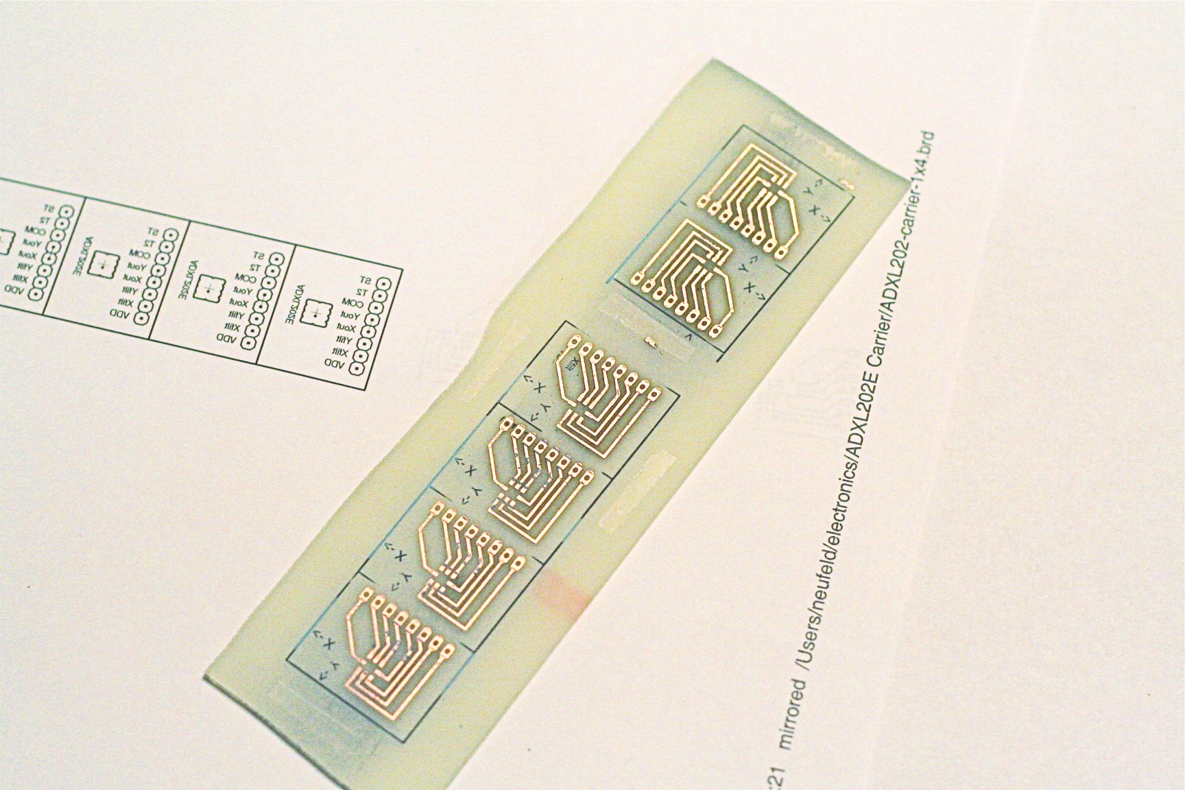
We did iron-on toner transfer etch resist, using Cort’s heat press. We also did toner transfer for the silkscreen-layer labels.

ADXL202 breakout boards

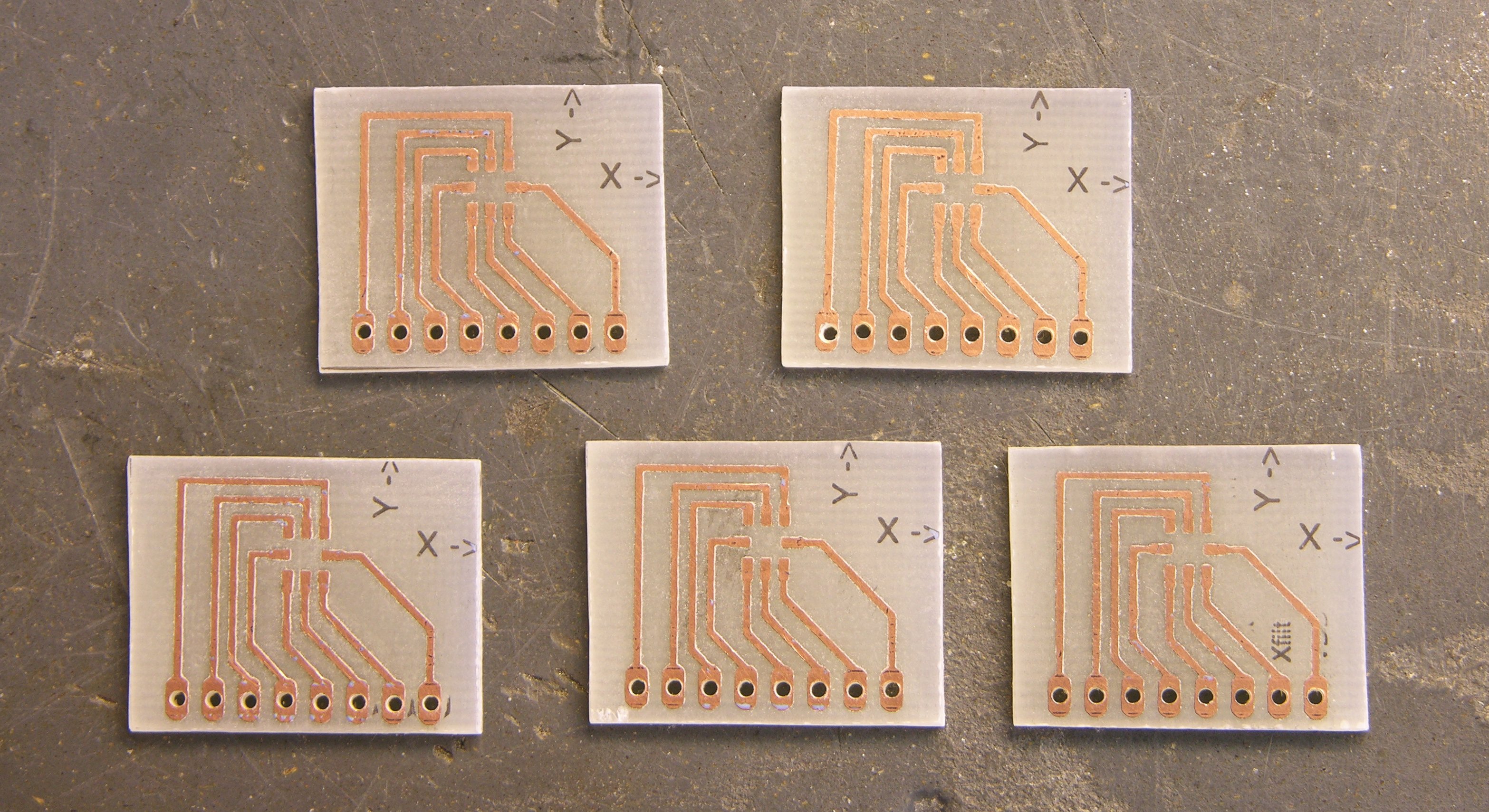
The boards came out very nicely, although the straightness of my hacksaw job leaves something to be desired. Besides indicating the positive directions of the X and Y axes, the silkscreen layer also had labels for the individual header pins; but they didn’t stick at all well going up and down the edges of the copper traces, so I scraped ‘em off. Ditto the pin-1 indicator for the LCC chip.

ADXL202 breakout board, top view

Here’s the board I’ve assembled, with header pins hand-labelled.

ADXL202 breakout board, LCC soldering

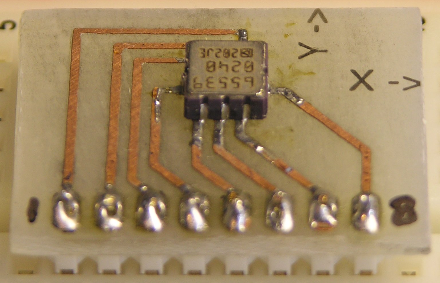
I used the Sparkfun SMT soldering method — slop solder on and wick off as much as you can. It leaves enough between the chip and the traces to make good contact, while eliminating solder bridges.

This was a bit interesting to position while soldering. Because it’s an accelerometer / tilt-sensing chip, I wanted its orientation as closely aligned as possible with the orientation of the carrier board. Absolute position doesn’t matter; but if it were rotated relative to the board, its readings wouldn’t align with the tilt of the project it was part of.

I knew I wanted to hold it securely in place while soldering, rather than tacking down a corner and hoping it was rotated about right while soldering the remaining pins. I thought about using a hemostat, but Cort’s was way too strong and would have crushed the chip. I ended up using a needlenose vise-grip, backing it off far enough to just barely grip the chip. I still worried about crushing it; but I was careful enough, as the accelerometer still works.

Tilt Menu Software and Prototype

The whole idea of tilt-menu-based control comes from reader Kevin Reid‘s suggestion:

Accelerometer-based control!

1. Press single control button.
2. Tilt puck such that the LED indicating the relevant function is lit.
3. Release button.

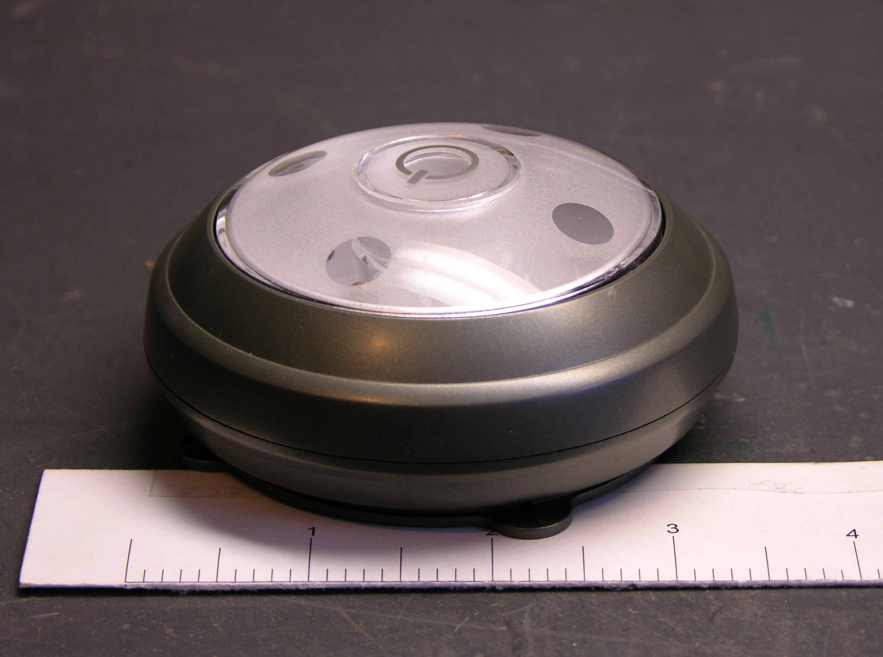
I don’t know whether that’s the exact mechanism (press/release) I’d like to use, but I love the overall idea. To clarify one point, the top of the puck will be rounded/domed, so tilting the puck will light the LED that’s “on top,” like an air bubble floating inside a liquid-filled dome.

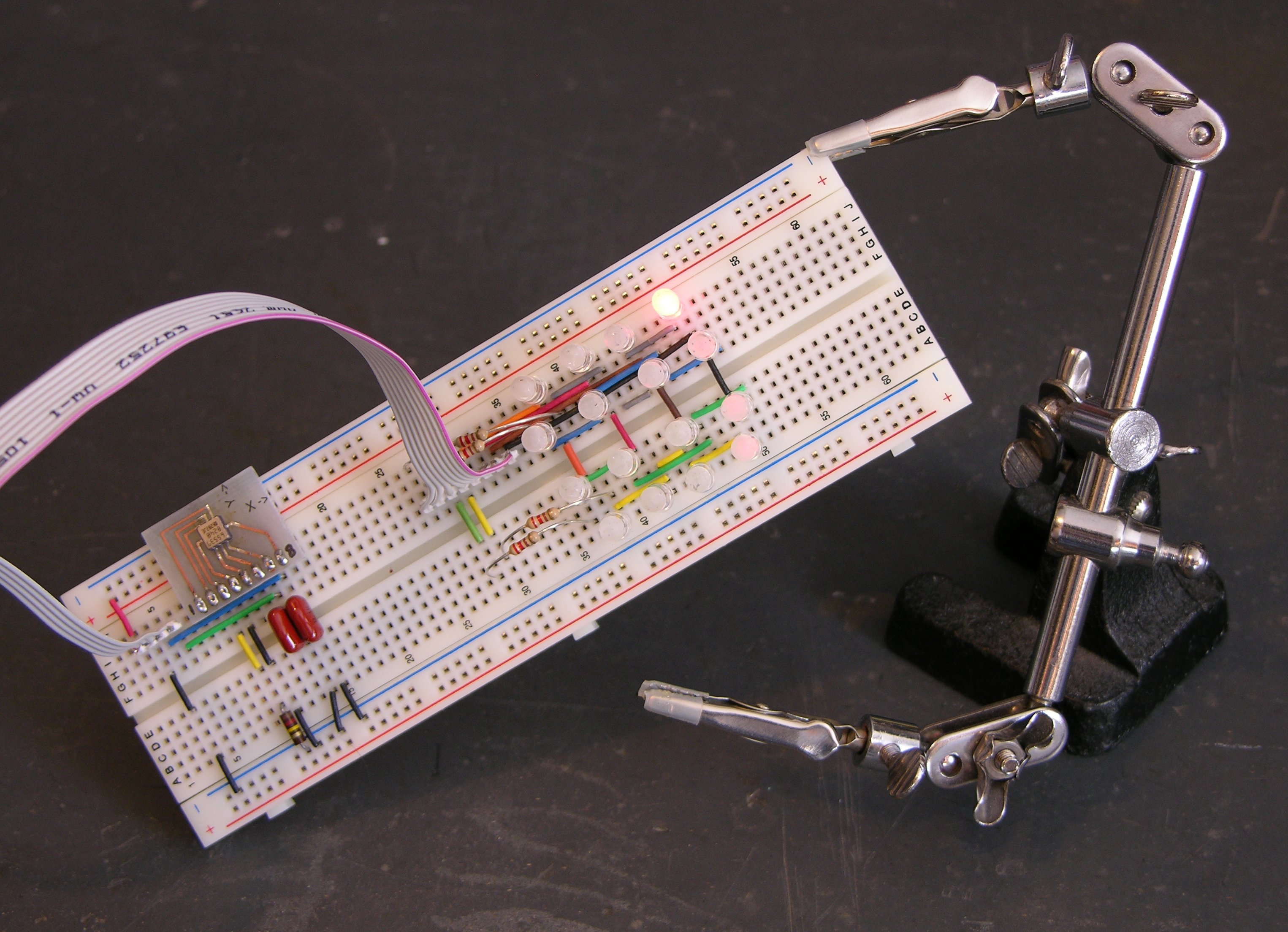
With the accelerometer breakout board completed, I was able to prototype the system.

Tilt menu prototype

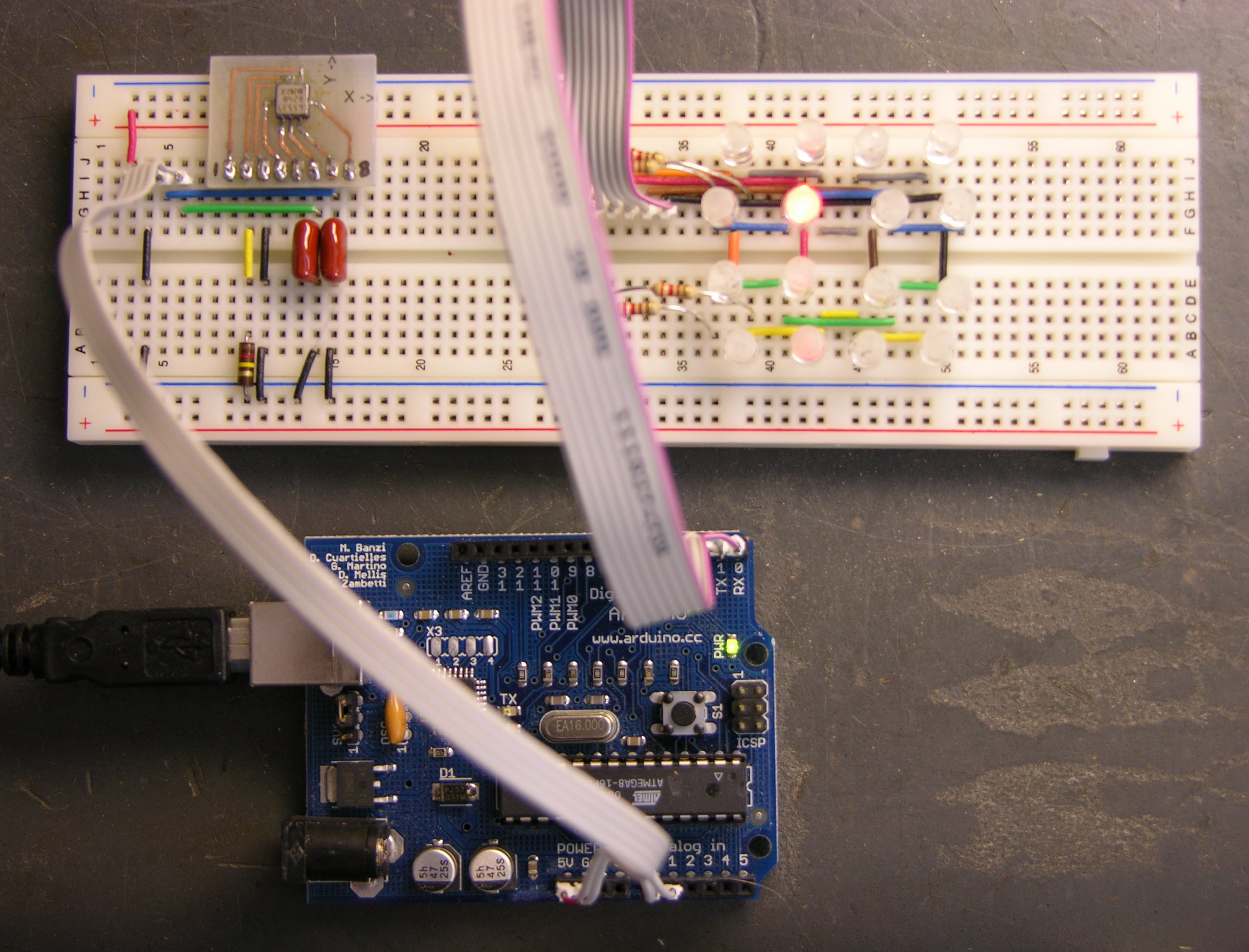
The Arduino at the bottom is the brains. The accelerometer is at the left end of the breadboard with fairly large signal-filtering capacitors — I sized them for about 50 discrete readings per second, which I think should be more than enough (and is still far fewer than the device is capable of). Note that I’m using the accelerometer’s analog outputs and the Arduino’s A/D inputs; I didn’t feel like measuring pulse length from the ADXL’s digital outputs.

The LED matrix at the right end of the breadboard is kind of ugly, at least to implement on a breadboard (as well as hard to see in this picture). I intend to use an Allegro MicroSystems A6276 16-bit serial-in, parallel-out, constant-current LED driver for the real thing . . . but I can’t find where I put mine, so I just hacked together a row/column drive straight out of the Arduino.

The Arduino code is nothing special, but here it is:

tilt_menu_demo.pde

It reads the analog inputs to get the X/Y tilt, translates from the scale of the A/D converters into the size of the LED matrix, and drives the row/column outputs. I added hysteresis that (although simple) does a fantastic job of keeping the LEDs from flicking back and forth when you’re on the fence between two adjacent ones. And I used tristating on the LED matrix drive because it made more sense to me to float unused lines than to flip them to the opposite value.

Tilt menu demo, flat

Here’s what it looks like sitting on a flat surface. One of the four center LEDs is lit — it turns out to be always the same one, as I haven’t calibrated the accelerometer readings for perfect level yet and it lists a bit to one corner. Note that one of the envisioned modes for the puck is a bubble level; and in that mode, I think I’d flash the four center LEDs to indicate when the puck is perfectly level.

Tilt menu demo, upper right

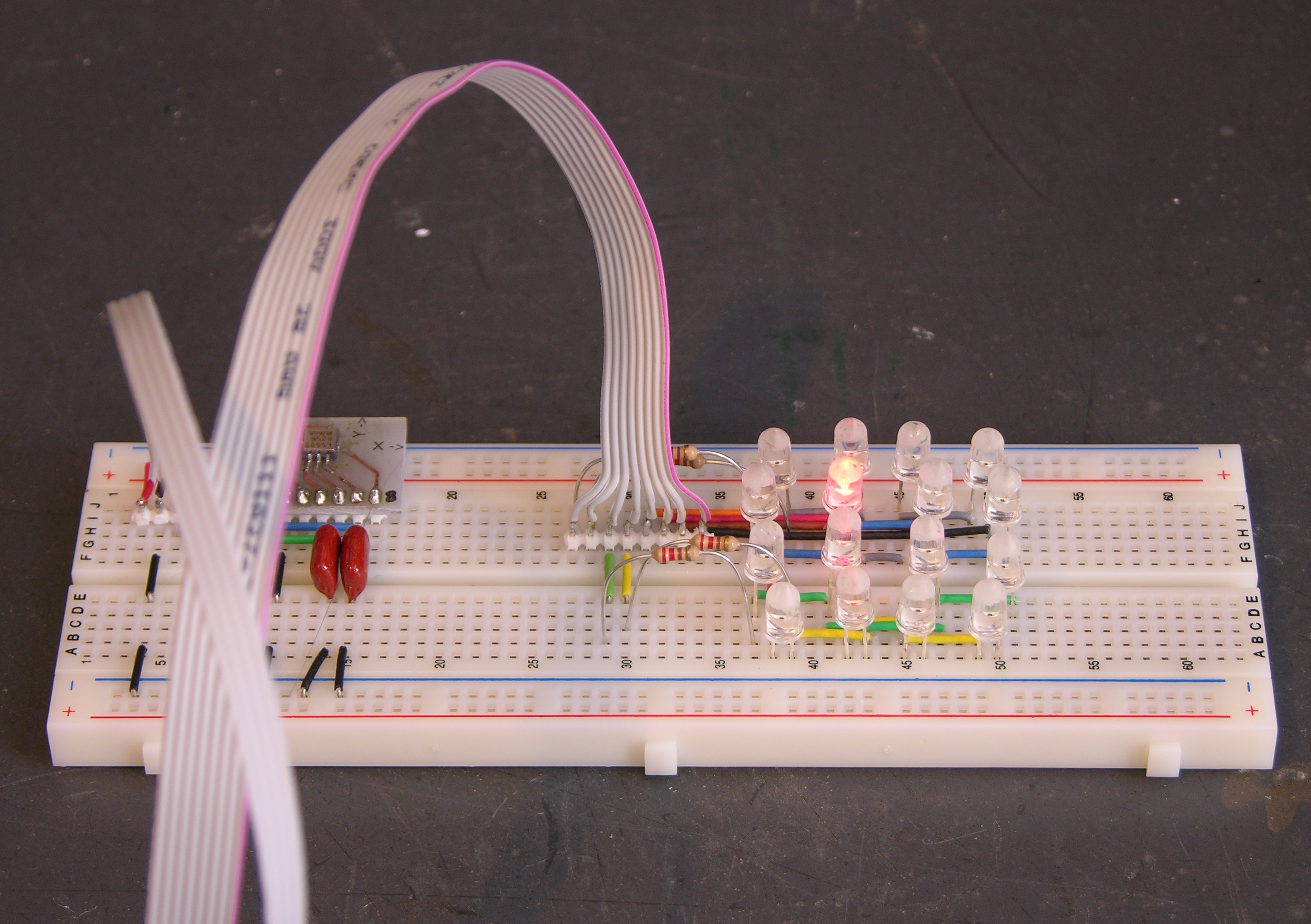
Tilted a little bit, a different LED is “uppermost” and lights.

Tilt menu demo, far upper right

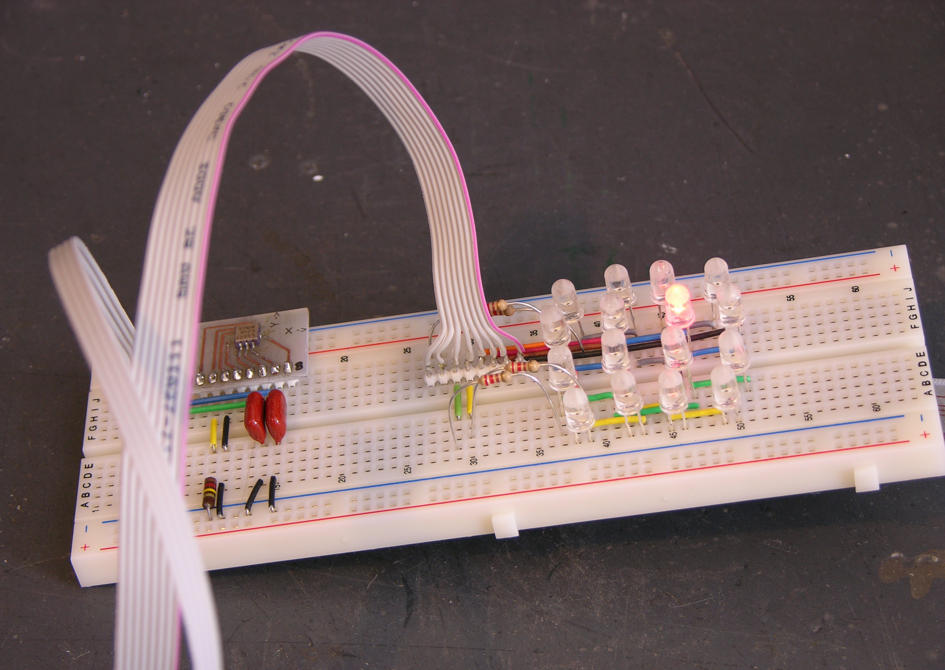
Tilted dramatically, the corner LED is “uppermost” and lights. Note that the amount of tilt required is set by the TILT_MIN and TILT_MAX values, so it’s easily adjustable for dome shape and/or user preference.

Not Really a Square Matrix

I indicated early on that I pictured LEDs around the perimeter of the puck angled slightly out for good dispersion, so the square matrix I made this weekend was just for a quick demo. I’m actually thinking of twelve LEDs around the perimeter (analog clock mode!) and four in a square surrounding the center, totalling the 16-LED capacity of the A6276 driver chip. I’m working up some very simple drawings of what it might look like, which I hope to post soon.

LED Puck: Comparison Shopping and Assignment

Saturday, December 15th, 2007

Maeve had several of these battery-operated, white LED accent lights, and let me borrow one until the next visit.

Commercial LED puck

It was a good opportunity to test a few ideas about the LED puck. If a commercial product was already on the market, albeit for a different target audience, maybe it’d be good enough and I wouldn’t need to design my own. More likely, I could identify and clarify design differences between their product and my own ideas, which is what turned out to be the case.

First, the LEDs in the commercial puck are pretty directional. When placed on a nightstand pointing at the ceiling, it illuminates about a 2′ diameter area. I’d like the puck to be much more omnidirectional, casting light as evenly as possible throughout a hemispherical area.

Second, it’s not bright enough. Used like a flashlight and pointed directly at a book, it provides more than enough light to read; but pointed upward, the diffusely reflected light isn’t quite enough to read by. I specifically want to be able to read by the light of the puck, and I’d need several more LEDs and somewhat more power to be able to do that.

Third, it’s too bulky, specifically, too thick. I could never carry it in a pocket. I have been carrying it back and forth to work in my laptop satchel, but I realize I’d like the puck (or one version of it) to be small enough to carry with me in a pocket all the time. What’s the point of having cool toys if they’re never with you when you need them?

Commercial LED puck, tilted

The light portion of the commercial puck tilts so it can be aimed, and the light portion is actually plenty small to carry around in a pocket. The whole enclosure is larger both to accommodate the tilting action, and because it houses three AAA cells.

The space needed to accommodate a power source concerns me. I’d like to find a flatpack LiPo battery, skinny like a cell phone battery; but I fear that power may be the driving constraint on overall puck size.

Homework Assignment

For anyone reading who’d like to build their own puck, or anyone amused enough by the idea to humor me, I have a homework assignment for you.

Find something round, (*) about the size that you envision the puck being, and carry it with you for a few days. Post a comment about what you used, its dimensions, where on your person you carried it, how comfortable/convenient it was, and whether you’d carry something that size with you all the time.

* (I envision the puck having a rounded profile like a drop of liquid sitting on a horizontal surface, rather than being an untrimmed cylinder. Rounding off the top would slightly improve the comfort of carrying it in a pocket, but cylinders that I’m able to find are good enough for a first test.)

Electrical tape container and peanut butter jar lid

I’ll start:

  • I’ve been carrying the commercial LED light in my laptop bag for a week. It’s 3 1/2″ d and just over 1 1/2″ thick. It’s way too thick to fit into a pants pocket; it fits fine in my laptop bag, but then so would a hardback book. I would always have it nearby, although never on my person.
  • My first inspiration for the physical form factor of the puck was the empty container from a roll of 3M electrical tape. It’s also 3 1/2″ d but only .9″ thick. It’s still the size that I think would look best for a puck, but it’s uncomfortably large to carry in a pocket, and I haven’t even tried. I would definitely carry it with me in my bag.
  • The peanut butter jar lid is 3″ d and 1/2″ thick. I’ve been carrying it in my back jeans pocket since last night, and I hardly notice it’s there; I’d notice it even a little less if the top edge were rounded. This would be a great size for carrying with me all the time — but there’s no way to fit both battery and outward-angled 5mm LEDs into that thickness.

Maybe two puck sizes will be needed — the original puck, in the electrical tape container size, and the porta-puck, in the jar lid size.

LED Puck Design Questions

Saturday, December 1st, 2007

Cost: Realistically, I see this thing climbing into the $15-30 range for materials. That’s more than I’d pay to buy a puck from ThinkGeek, but not more than I’d pay to construct one myself that I helped design. Anyone else?

Battery: Seems like we’d get a lot better power density (translating to smaller size and longer runtimes) if we used an RC-style LiPo battery, I’m thinking about the size of a matchbook or so. This’ll be more expensive; but I’m concerned that fitting in 2-3 AAA or AA cells will make the puck bulky that it’s not cool anymore. How do you feel about having to buy a special battery for it?

Charge circuit: I can find a charge-control chip and use the datasheet’s sample implementation as well as the next guy; but that’s really just a starting point, and I understand there are often subtleties involved in getting the best real-world performance. Does anyone have a lot of charging circuit design experience, or know someone who does, who’d be willing to design that portion and contribute it to an open-source hardware, community-developed project? We might want to look at LadyAda’s WaveBubble or the Chumby design for reference.

Voltage-boost circuit: Depending on what battery, microcontroller, and LEDs are used, we may need to boost the battery voltage. Same questions as on the charge circuit.

Surface-mount components: I don’t think there’s room to use through-hole technology. I’m envisioning at least the microcontroller, LED driver, and optional real-time clock chips being SMT. LEDs need to be through-hole, in my opinion, both for rated brightness and so they can be aimed slightly away from the center for better light dispersion. Will a few SMT components be enough to keep anyone from building this who would otherwise be interested?

Enclosure: My first thought was pouring this thing in resin, but I’d really like to be able to take it apart and service / enhance it. I’m now leaning toward a two-piece milled enclosure (probably lexan) that would sandwich the PCB edges in rubber for shock control and hold together with recessed screws underneath. Add an appropriate O-ring and the whole thing could probably be made watertight — which in my book counts as another feature. :-) Thoughts?

What Features Do You Want in an LED Puck?

Wednesday, November 28th, 2007

Underworld: Evolution features hockey-puck-sized bombs that click open, disperse visible vapor, and then blow up real good.

Why should the destructive guys have all the fun? I’m inspired to make design an LED puck, for special-purpose lighting. Power goes out and you need to enough light to shut down the UPS-protected computers? LED puck. Camping and you need to find your gear inside your tent? Puck. Kidnapped and locked inside a trunk? Puck. (Also “cocktail party,” but that’s a different movie.) It’s dark and you want to show off a cool gizmo? Puck!

My friend Joel can help me cast it in clear resin to protect the LEDs — but casting it in resin makes it harder to tweak later, so I’d like to get the feature set right on the first try.

What would make for a cool LED puck? Here’s my list.

  • Fairly even light dispersion through a hemispherical pattern. That is, it illuminates the room, not just the ceiling.
  • Enough light to read by at 5′.
  • Can use rechargeable AA or AAA cells. And/or:
  • Can use “Joule thief” technology to use all of an alkaline.
  • Hardy enough to toss around. Like the bombs.
  • Physical on/off switch.
  • Jack for (wired) remote on/off control. (Increases flexibility to use as something other than a lantern.
  • Wireless, addressible remote control. Can control multiple pucks individually. Keyfob. Choop-choop sound. Okay, forget the choop-choop.