Archive for the ‘Ideas’ Category

LED Calculator Prototyped with LCD

Friday, February 8th, 2008

I still want to find a small LCD module for the LED calculator, so I can fit the whole thing into a box with a footprint about the size of a deck of cards. But for prototyping, I have a stack of 2×16 LCD modules about 3 1/2″ wide (viewable about 2 1/2″) from Slim, and Wednesday night I got one hooked up and working.

They’re Optrex DMC-16207 modules, and they seem to be using the Hitachi chipset that everyone uses, or at least an equivalent, although I didn’t know that at the time. Searching online, I had a hard time finding data on this exact module, but came across a mechanical drawing, a module user’s manual, and finally a full datasheet.

Interfacing the Arduino and LCD

I dived in and wrote my own LCD interfacing code. I found out in retrospect that there are several other Arduino LCD interfacing projects out there:

But all of them are using hard-coded delays to pause while the LCD processes commands, rather than checking the busy flag. To be sure, I’m doing the same thing right now in my first draft of the code; but I’m going to go back and clean it up to do it right.

Also, I haven’t checked all of them, but at least one is using digitalWrite() to manipulate each bit of the port register individually. Since I’m dedicating eight Arduino lines to the LCD’s I/O port, I can write the port register as a byte rather than twiddling individual bits, saving time and effort.

My goal will be to write a nice library module/class that encompasses these different approaches (8-wire vs 4-wire, busy flag vs hard-coded delays, read/write interaction vs hardwired write-only) and presents a clean interface to the programmer to select the options. Of course, for now, I just wanted to get it up and running.

I found this ATmega to Arduino pin mapping, which confirmed that Arduino digital lines 0-7 are PORTD lines 0-7. And the Arduino port register reference shows that DDRX and PORTX are defined as Arduino variables; so writing to a port is as easy as PORTD = $ff . It’s very nice that they left those low-level features exposed, even though in most cases it’s better to use the higher-level interface for portability.

Calculator Prototype

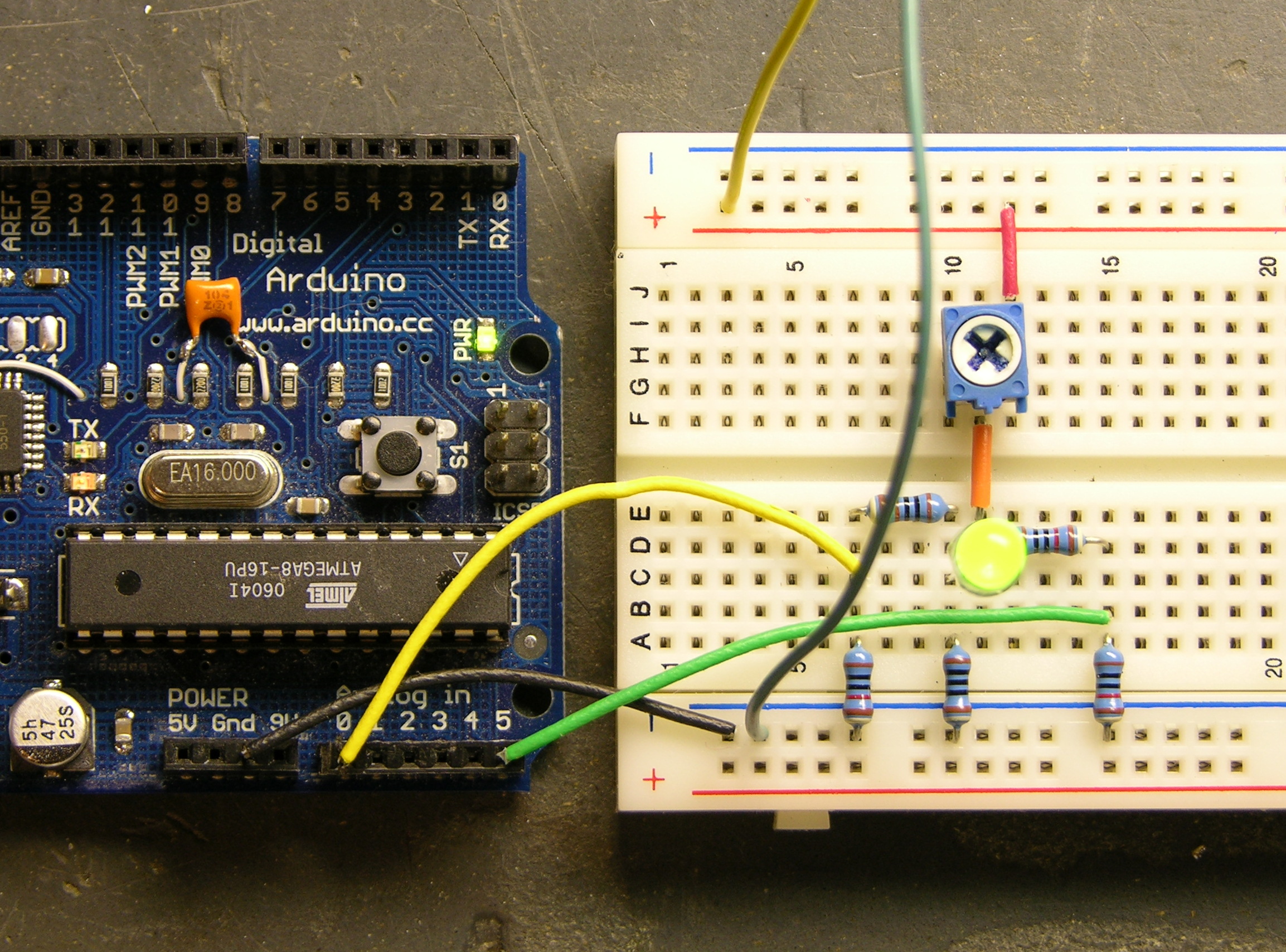
So here’s the work in progress.

LED calculator prototype with LCD on breadboard

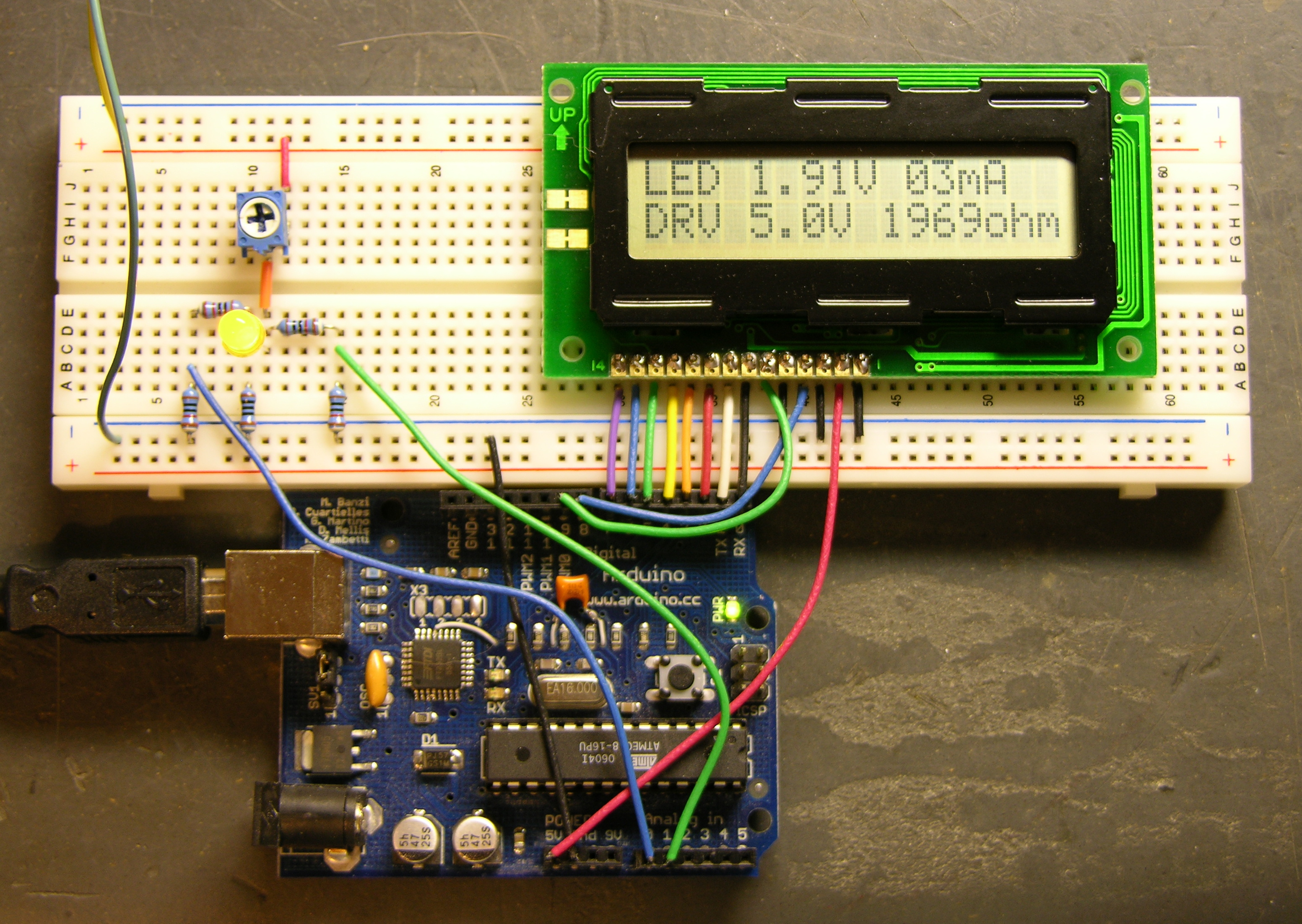
The Arduino is getting power from USB and supplying 5V power to the LCD. The LCD contrast is hard-wired to ground. Although it actually looks pretty good right now, I’ll want to put in a potentiometer to adjust contrast. And I’m still using my bench power supply to run the LED circuit at 9V.

I don’t have a method built to select the voltage of the target circuit — the software is assuming 5V for now. The easy thing to do would be pushbuttons to bump the desired voltage up and down. It’d be kind of fun to do it with a spinny-wheel, although I’m not sure how much that would increase the cost, and I’m concerned about overengineering this thing if I really want to offer it as a kit. Maybe another potentiometer is a good compromise.

However the target voltage is selected, I need to determine the selectable range (which could of course be overridden by an owner with an AVR programmer). I’m thinking 3 – 15V in .1V increments. Is that enough?

LED Calculator Breadboarded

Saturday, February 2nd, 2008

After receiving some encouragement, I went ahead and breadboarded the measurement circuit for the LED calculator. Someone may suggest a better way to do it, but here’s what I’ve been carrying around in my head:

LED calculator drive circuit

R2, a 1KΩ potentiometer used as a variable resistor, controls the LED brightness. R1, a precision 100Ω resistor, limits the maximum LED current and acts as a sense resistor.

By measuring V1, we can calculate I1 = V1 / 100Ω. Since ILED = I1, we’ve determined the LED current. And VLED = V2 – V1, so we can determine the LED voltage drop as well.

The value of R2 isn’t critical. With a supply voltage of 9V and a very low LED drop of 1V, a 1KΩ variable resistor allows us to test LED currents down to (9V – 1V) / (1KΩ + 100Ω) ≈ 7mA, which is probably low enough for most applications. To be able to test lower, increase the range of R2.

Test Measurements

I built this much of the circuit and took measurements of a few different LEDs at a few different brightnesses, to make sure the potentiometer would really work the way I expected, and that I hadn’t made any stupid mistakes in the voltage calculations.

Color V1 V2 VLED ILED
green .71V 2.70V 1.99V 7mA
2.00V 4.04V 2.04V 20mA
3.45V 5.55V 2.10V 35mA
red .73V 2.55V 1.82V 7mA
2.00V 3.88V 1.88V 20mA
7.28V 9.24V 1.96V 73mA
blue .61V 3.61V 3.00V 6mA
1.12V 4.23V 3.11V 11mA
2.00V 5.27V 3.27V 20mA
5.56V 9.24V 3.68V 56mA

The measurements make sense — each LED’s forward voltage drop increases slightly as the current increases. If I remember my semiconductor theory correctly, that’s called the ohmic region of operation, in which a diode behaves like a very low-valued resistor.

Automating the Measurement

In a self-contained LED calculator, the voltages will need to be read by a microcontroller, which will also drive an LCD. For now, I used my Arduino and had it send results to the host computer.

Depending on the position of potentiometer R2, V2 can range up to the supply voltage of 9V (or whatever); and V1 can range up to the LED’s forward voltage drop less than that. I’m pretty sure the microcontroller’s A/D converters don’t like inputs over 5V, so I needed to divide V1 and V2 to lower their ranges before feeding them into the ADCs. I used two pair of precision 10KΩ resistors for that.

LED calculator measurement circuit

All put together on the breadboard, it looks like this.

LED calculator circuit, breadboarded

And with a little Arduino program running to read the inputs, scale from 1024 steps back up to a range of 5V and then double to compensate for the voltage division, and calculate all the values, I get this.

Output from LED calculator Arduino prototype

Putting It in a Box

I’ll probably program an Atmel chip directly, because I don’t need all the USB baggage. Even a Boarduino has prototyping parts on it that I don’t need here.

I need to think carefully about the LCD screen, to have enough room to display all the information and still be small enough to fit into a reasonable project box. A cell phone screen would be the perfect form factor, but really drives up the cost and complexity. I think about a 4×16 character display would be okay; 4×10 would be tight for the text and I’m afraid 4×20 would be too wide for the box.

LED 2.10V 35mA
DRV 8.4V 180ohm

Okay, 2×15 is a bare minimum. All Electronics has a 2×16 module that’s 4″ wide and another that’s 3.15″ wide, which suggests having to build the calculator in landscape mode. Not wild about that. Digi-Key has 4×16 starting at $27 and — hey! — a comparatively svelte 2.6″ wide 2×16 at $5.88.

Project Idea: LED Calculator

Saturday, February 2nd, 2008

When I want to know what value current-limiting resistor to use with an LED, the easiest thing to do is assume 5V supply / 15-20mA / old-school LED / 220-330Ω resistor, like we all learned from Forrest Mims in the 70s and 80s.

And then I tweak the resistor until the LED is as bright as I like, by trial and error.

Oh, most of the time I use my LED tester to estimate the current I need for the brightness I like. At $6-10, it’s indispensible. Also double-checks anode/cathode pinning and tells me if an LED is burned out.

LED tester

But running on a 7.2V supply (NiMH “9V” battery) with fixed current-limiting resistors designed for a 9V supply and low-forward-drop LEDs, it’s not really representative of what’s going to happen when I put a newer-chemistry LED with a 3.5-4V drop into my 5V circuit. So it’s back to trial and error.

I want a microcontroller-based LED tester/calculator that:

  • has a socket for the LED
  • has controls to set the target-circuit supply voltage
  • has a current knob to turn until the LED is at a brightness I like
  • displays on an LCD the target circuit supply voltage, the LED voltage drop, the LED current, and the value of resistor to achieve that current with that supply voltage
    (That is, all the facts about the LED I’m testing, and the resistor value I need to use in the target circuit)
  • is about the size of my existing LED tester

Note that the tester need not be running at the target circuit’s voltage; we can calculate resistor values for arbitrary voltages once we know the desired LED current. It does need to have a higher supply voltage than the forward drop of new-fangled LEDs, and I’m inclined to run it on a 9V for compactness and simplicity.

I’ve been kicking this around for quite a while, and I’d really like to make one. And publish the plans and code for DIYers and make circuit boards and kits for kitbuilders.

Is that the right feature set? I personally never put LEDs in series, but should the tester be able to calculate for that anyway? What else?

Project Idea: Household Pager

Sunday, December 23rd, 2007

When we’re doing several other things at the same time as baking, it’s easy to forget to check the oven, and things get burned. When we’re watching a movie and the phone rings, it’s annoying to have to go to the phone to check the caller ID to see whether it’s worth interrupting for.

I want a household pager that vibrates and has a single-line alpha display. Range limited to my house, and integrated with everything.

Set the oven timer; when it goes off, the pager says “Oven timer.”

Incoming phone call, pager shows the caller ID. Doorbell could show “Doorbell,” in case we were upstairs where we can’t hear it.

Washing machine, dryer, or dishwasher finishes running, pager lets you know.

Integrated with everything in the house, I think it could be incredibly handy. Sensor modules could be serial-numbered, so you assign text to functions in the base station rather than at each sensor. Of course, the trick is integrating with everything in the house.

Project Idea: Solar Sidewalk Melter

Sunday, December 16th, 2007

Our driveway is on the northwest side of our house, and the sidewalk beside it stays shaded and icy even when the front walk has melted dry.

Put a 2′ diameter mirror on the west edge of the roof to reflect sunlight down onto the sidewalk, with servos to aim. Photosensors could detect whether the sky was clear enough to be worth tracking the sun, or it could just do it anyway. Sweep back and forth along the length of the sidewalk on a one-hour period, to melt and dry the whole thing evenly.

It could use solar declination and time of day to calculate aim totally open-loop, or use photovore behavior to track the sun and then calculate the appropriate angle to aim at the sidewalk, or put sensors beside the walk to run as a remote photovore, or put a camera by the mirror and watch where the bright spot is. Or recognize that I only need it to work in the winter, assume a known solar declination, and write a fixed program for solar tracking and sidewalk sweeping.

Two addenda:

I’m talking about a flat mirror, not a solar death ray. One sunlight is enough to clear the front walk; that’s all I want to add to the driveway walk.

I’m not a mechanical engineer and I can’t quite picture it, but it seems to me that it might be possible to make one motorized photovore to track the sun, one motorized sweeper to move a pointer back and forth aimed at the sidewalk, and attach the mirror to a geared angle-splitter that bisects the angle between the two.