Archive for the ‘TechArt’ Category

LogoChip Desktop Serial Port Configuration

Tuesday, February 21st, 2006

After learning of the ! print portnames command from John, I finally got my PowerBook’s LogoChip Desktop Software talking over my USB serial to my LogoChip.

Turns out the Classic mode support and the Java serial communications driver installation error were red herrings. The problem was simply that LogoChip Desktop was defaulting to the first serial driver in the list–which was the IrDA driver. Since my desktop computer doesn’t have IrDA, it picked the USB driver–the only one in the list.

The solution was simply to update my config.txt to read:

com-port: /dev/tty.usbserial0

I had previously tried changing it to usbserial0, but it didn’t recognize that format. It was the ! print portnames command that led me to the device-file syntax.

And it works. Hooray!

Detailed instructions on the class wiki.

Project Idea: Flash Subliminals

Monday, February 20th, 2006

(Originally sent to the class mailing list)

Here’s a project to carve up single-use cameras and make their flash project a very short message through the lens onto a surface:

http://www.hactivist.com/flashpoint/

If this actually works, it could be kinda interesting to have in the gallery. And I have a box of these at home that I could contribute.

Question for someone who knows ShiftSpace: Would there be somewhere we could have a light-colored wall (or projector screen), dark lighting, and a box sitting in front of it that randomly flashes messages onto the wall?

Question for everyone: Let’s say we could have four different frames, sequenced somewhat randomly. The flash will be so quick, you won’t be able to see the images long enough to read or distinguish them consciously–if words, say a limit of ten letters; if images, then something simple. What messages or images would you like to project?

Project Idea: Cell Phone Abuse

Friday, February 17th, 2006

(Originally sent to the class mailing list)

I know it’s a little late to be adding more ideas, but I just had another one walking back from class. Kinda jumped out at me, in fact, for reasons that’ll be obvious once you read it.

Cell phones have ushered in all kinds of new inconsiderate behavior–erratic driving; loud, personal conversations in quiet public spaces; etc. But my personal favorite most hated behavior is when you pass someone on the sidewalk and they say, “HEY! HOW ARE YOU!,” and you look at them like who the heck are you, and then you see they have a freakin’ borg implant on the side of their head and they were talking on the darn phone.

Project idea: Make a display with a few heads that illustrate the worst cell phone abuses. They wait until people get close and then carry on conversations, they shout things but they’re really to someone on the other end of the phone, etc. I dunno, several heads clustered together apparently talking to each other but then the conversations diverge and you realize they were sitting together but talking to other people. You could have three in one part of the gallery and two in another and once in a while they’re talking to each other (which would take a fairly clever viewer to figure out).

If you made enough rude behaviors, it could take a long time (15-30 minutes) to cycle through them all. Most viewers probably wouldn’t stay for the whole thing, so everyone who saw it would witness a slightly different portion and get different things to talk about with their friends.

Mini Pumps

Saturday, February 11th, 2006

Serendipity strikes again! After thinking up the idea for a dancing water fountain, I was stumped on where to find pumps to circulate the water, but remembered that Harbor Freight somtimes has pumps for outdoor waterfall displays. I checked their flyer that I had just received, and they had not one but two different small pumps on sale this week, for $5 and $10! One of them even specifically listed tabletop fountains among its applications!

I dropped by Harbor Freight last night and bought both pumps. After trying them out in the sink, I’m pretty sure the larger one will work for my fountain, although the smaller one sure is cute. :-)

Smaller Pump

The smaller pump is Harbor Freight item number 45303, rated for 66 gallons per hour. It has a 1/2″ outlet and a 1/4″ adapter, which makes a stream barely larger than what I’d like for one of the jets in my fountain. It was on sale for $4.99, regularly $9.99.

Harbor Freight Mini Pump #45303

When I first tested it, I had it stuck flat on the bottom of the sink, and its own water splashing down on top of itself disturbed the surface of the water enough that it was trying to suck in air, and the water stream “lurched” as it got water, didn’t get water, got water again, etc. Then the suction cups on one side popped loose (mental note: don’t expect the pump to stay in place under power of its suction cups alone) and it leaned to one side, making an arc of water that was much less disruptive and more photogenic.

Not large enough to power eight (or sixteen) jets, though.

Larger Pump

Perfection! Harbor Freight item number 41287 is rated for 190 gallons per hour, which turns out to be more than I think I’ll need, but it’s adjustable. It has a 1/2″ outlet that makes quite a stream! It was on sale for $10, regularly $17.99.

Harbor Freight Mini Pump #41287

The inlet has a rotating “switch” (visible in the photo on the Harbor Freight web site) to limit the amount of water taken into the pump. The photo above shows the amount of output at the second-lowest setting, which is about as far as I wanted to go in the sink–but it can put out a lot more water if it turns out that I need it. This is definitely the right pump for this project, and it was CHEP! Hooray!

Several observations:

  • I think I’ll want to build a completely submerged enclosure for the pump. That presents the complication of making good enough seals to get the power cord and the outlet tubing through the enclosure without leakage. It also complicates replacing the pump if/when it fails.
  • While prototyping, I’ll need to be able to access the inlet “switch.” That means that I can’t seal the pump into its enclosure until I’m sure I know which setting will provide the right amount of water.
  • From what I can see of the impeller design, the pump won’t suffer if its output is constricted or cut off entirely. That reduces the need for a bypass valve and simplifies my work.
  • I looked for clear tubing in the store to go with the pump and couldn’t find any, so I’m kind of annoyed that they list it for cheap (25′ for $3) on the web page right next to the pump.

Placeholder–Art Lab with Barry Badgett

Saturday, February 11th, 2006

Project Idea: Dancing Water

Wednesday, February 8th, 2006

The Concept

At last, I have an idea for a Technology: Art and Sound by Design final project. I’ve been struggling to think of anything interesting to do. As a musician, I’m dissatisfied with the beeps and boops that we can make with little chips; as a technologist, I’m more interested in building robotics that aren’t very artistic. But this morning, something clicked: I’d like to make a dancing water display.

I’ve been enchanted with dancing water fountains ever since I visited Disneyworld about twelve years ago. They have an amazing display with “snakes” of water frolicking from pot to pot and even leaping across the sidewalk over the heads of the guests. I’ve also watched the choreographed fountains at Atlanta’s Centennial Park, and recently I ran across the overview of a tutorial project called the Geyserbot at Bruce Shapiro’s The Art of Motion Control.

What

I’m thinking of a small display most akin to the Geyserbot–probably even a bit smaller (’cause it looks like it’s standing in a wading pool). I’d like it to be relatively easy to move around in order to display, and self-contained in a case to hide all the guts from the viewer. If it were ever formally exhibited, I might include a placard with a photo and description of the internal mechanism.

Complexity could be added in stages. First, get a basic mechanism running, with say eight jets (= 8 bits of control). Even if it did nothing more than the Geyserbot demo video–sequence the water jet to move back and forth down the line of nozzles, or shoot off alternating nozzles–I think it’d still be pretty interesting. Advanced versions could have more jets (maybe switch to the 40-pin version of the LogoChip with more I/O ports) and more choreography. If the valves could be actuated rapidly enough, it might even be possible to shoot simple pictures into the air–a heart shaped out of rising water droplets, for example.

I think I’d start with eight jets in a row pointing straight up, but it wouldn’t be hard to move them into a circle, tilt them inward so the jets met in the center, etc. With more jets, you could have sixteen in a circle with half pointing up and half pointing in. Lots of possibilities!

I haven’t decided whether I’d like it to be synchronized to music a la the Wizards of Winter Christmas display (which is a real display using a very high-end light sequencer, BTW), or silent except for the sounds of water splashing. Sequencing to music is obviously more difficult–and I don’t know whether it would really add anything. I rather like quiet sounds of water.

How

Since a pump takes longer to start up and shut off than a valve takes to open and close (I assume), I envision having one pump overall, and an electrically-operated valve for each jet. I don’t want the water to spray particularly high into the air–I’m more interested in having fat streams of water than thin sprays–so I think I’d need relatively low water pressure. It may be difficult finding a pump as slow/small as what I need (a small fraction of a cfm, by my estimations), so I might have to inflate some kind of bladder and use a pressure switch to turn the pump on and off on demand. And I’d be very interested if anyone has suggestions on where to get a pump and affordable valves–add a comment to this post if you have ideas!

Control is easy–start with eight jets and wire them to a single output register on the LogoChip. Build MOSFET drivers with back-EMF diodes for the valves, and I’m good to go. Eventually it’d be nice to have a sequencer program like Tom McGuire showed us on his drum machines, but I’d probably start out programming the jets by hand.

I’d like to build it into a case, and I haven’t thought much about what would be most appealing. I know I’d like to have the nozzles barely protruding from a pool of water, both from an aesthetic standpoint (hide the technology and focus on the art) and from a practical one (I think the pool will help dissipate splashing as all the water falls back down).

I’m not sure about the enclosure, though–what kind of material would be appropriate. I don’t want anything high-tech or flashy like aluminum to distract attention from the water show. The weathered metals we saw yesterday in the art workshop were gorgeous, but I don’t know whether they’re right for this project (and whether I could make them happen in time). I’m most comfortable working with wood, and a cherry enclosure (my old favorite) might not be too bad.

Comments welcome!

Got Beep

Monday, February 6th, 2006

Read the Manual, Stupid

Last week when I was trying to get the piezo buzzer to work with the LogoChip, I was in such a hurry to get to the sound that I skipped this part of the instructions:

Upon powering up, all of the user accessible pins on the LogoChip are configured as “inputs”. . . . Therefore, for the exercises in this document, we would like to always have all of the portb pins configured as outputs. . . . This can be done by creating the following special powerup procedure.

to powerup
write portb-ddr 0 ; turns all of portb into outputs
end

Last night when I soldered pins onto the piezo buzzer from the pager, plugged it into the LogoChip, and still couldn’t get sound out of it, I knew something was up. Finally it dawned on me that I didn’t know which way the ports were configured at boot, and looked at the getting started guide closely enough to find the section I quoted above. With the ports configured as outputs, it beeps just fine. Duh.

Beep Volume

I’m surprised at how quiet the beep is running on 5V, compared to how obnoxiously noisy the beep is in a pager on 1.5V. I changed back to the beeper from the microwave and it’s a little louder, but not much. Is the 1.5V in the pager really getting stepped up somehow? Tiny transformer, or voltage multiplier? Maybe I just need a driver transistor; I guess some experimentation is in order.

Beep Code

Making a beep was cute and simple, but booooring, so I made a little warbly sound.

to powerup
        write portb-ddr 0            ;   set port B to output at power-up
end

to startup
        warble 3                     ;   "warble" three times when the Go button is pressed
end

to click-on
        setbit 0 portb
end

to click-off
        clearbit 0 portb
end

to delay :n
        repeat :n [no-op]            ;   waste time by doing nothing, several times
end

to note :period :duration            ;   play a note of a given pitch for a given duration
        repeat :duration [           ;   repeat as long as requested
                click-on             ;   make a sound
                delay :period        ;   wait a little bit
                click-off            ;   make another sound
                delay :period        ;   wait another little bit
        ]
end

to warble :times        ;   make a warbly noise several times
        repeat :times [
                note 2 200           ;   make a low-pitched sound
                note 1 200           ;   make a higher-pitched sound
        ]
end

Of course, downloading a routine named powerup doesn’t automatically invoke that routine (unless you reboot the chip), so I invoked it manually from the console. Having done that, the routine makes a nice little warbly noise any time you type warble # at the console, or press the “Go” button on the circuit board.

Another thought: Since note‘s duration code loops around calls to the click-on, click-off routine, which calls delay to set pitch, the duration is actually impacted proportionally to the pitch of the note. It’d be interesting to rewrite the duration code to take input in ms (or seconds) and check timer to see when we’ve played the tone for long enough.

Pitches and Timing

If the code makes sense to you, then you’ll notice that I’m calling the delay routine with the second-shortest and shortest possible delays–twice and once through the loop. With delays of 2 and 1, the second pitch should be an octave higher than the first (twice the frequency)–but in practice, the one sound is only about a minor third higher than the other. That means that the overhead of calling the delay procedure is much higher than the delay of running once through a timing loop around a no-op.

Here’s the math: a minor third corresponds to a frequency difference of the fourth root of 2 (in equal-tempered tuning), whereas an octave is a factor of two. So if there were no overhead for calling the procedure, then the respective frequencies and periods would be simple doubles of each other:

f2 = 2f1
p1 = 2p2

But in practice

f2 = 4√2 f1
p1 = 4√2 p2

Let’s define tcall as the duration of the function call overhead (which should be constant) and tnoop as the duration of one trip through the loop in the delay procedure, including both loop overhead and the no-op operation (which we’re told is 13ms). (This ignores the fact that loop overhead will be slightly different when repeating and when exiting, but I suspect that the difference is small enough to be irrelevant. If anyone wants to check, I can measure frequencies for more delay values and give you equations in three variables . . .)

p1 = tcall + 2tnoop
p2 = tcall + 1tnoop

Then substituting back into the period relationship

p1 = 4√2 p2

tcall + 2tnoop = 4√2 (tcall + tnoop) = 4√2 tcall + 4√2 tnoop

2tnoop4√2 tnoop = 4√2 tcall – tcall

(2 – 4√2) tnoop = (4√2 – 1) tcall

tcall / tnoop = (2 – 4√2) / (4√2 – 1) ≅ 4.3

So if I did all that right (and I confess I ‘m pretty rusty), the overhead of calling delay is a little more than four times the delay of one trip through the no-op loop. Hmph.

Regardless of the relative values, the actual frequencies aren’t particularly high–higher than 440Hz, but well within the limits of my hearing. (I should test them tonight with my frequency counter.) That’s a bit disappointing for a 5Mhz-clocked chip running flat-out in a busy wait.

I thought about clocking the chip up to 40MHz per the instructions in the getting started guide (8x the clock speed = 3 octaves higher = outside the limits of my hearing), but I didn’t order the crystal and I didn’t have two 10Mhz crystals in my parts bin. Shucks.

I just talked to John, and he said that he and Tom McGuire were able to produce higher sounds using the chip’s built-in PWM. Not bad for a hack, but I wanted to use both channels of PWM for motor control. Think I need me a crystal.

Starting up the LogoChip

Thursday, February 2nd, 2006

Introduction to the LogoChip

A lot of the work in the Technology: Art and Sound by Design class will revolve around the LogoChip, a PIC18F2320 microcontroller (~$8 in 28-pin DIP) with scads of I/O pins and a Logo byte-code interpreter. (The Logo code is compiled on a host computer and downloaded to the chip.) The getting started guide gives examples to flash LEDs, beep piezo speakers, and move Lego motors.

The chip looks very promising for my own hobby use as well. I’ve been intending to dive into microcontrollers for a long time, and always assumed it’d be PICs. I have a BASIC Stamp (and a separate PIC) on my SumoBot, so that’d be one entry into microcontroller programming; but the LogoChip appears to be even easier to get into.

I’d been planning to follow up to my tilt sensor project with a PROM-based controller, but a little logic tells me that I’d need to quantize the sensor’s PWM output into at least 32 slices to get acceptable motor behavior, and that’s a lot of work to do in discrete logic. I’m afraid I’d overload my small motor just with the weight of the TTL DIPs required to do that. I had really wanted to build a motor controller without a microcontroller, just to show myself that it could be done, but I think it’s time to move on.

Building Circuits

The last two nights, I’ve breadboarded the LogoChip circuit, got it communicating with a host computer, and successfully built the cloning circuit to program the LogoChip code into the blank PICs I bought. The road to success was paved with annoying obstacles, though.

The getting started guide gives a schematic and step-by-step instructions to lay out the supporting circuitry on a breadboard. Of course, I’m stingy with space (I want as much room left over for other components to experiment with), so I managed to collapse the circuitry into the smallest possible amount of space. I saved .4″ over their design! Woo-hoo!

LogoChip on Breadboard

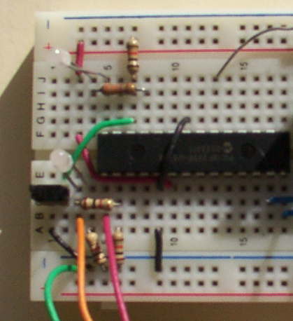
But I built and tested it using my bench power supply, forgetting that I was planning to power it with a 9V battery and 7805 voltage regulator. After I had it all working, I didn’t have room to add the 7805, so I had to stick it down at the other end, move the power switch, etc. ERROR.

LogoChip and 7805 Voltage Regulator on Breadboard

Also, the guide’s schematic for the serial interface disagrees with its visual layout instructions, and the schematic is incorrect. The indicator LED and its current-limiting resistor need to attach directly to DB-9 pin 3 (the host’s TD / chip’s RD), not to the chip’s C5 (pin 15) as shown in the schematic. When attached to C5, it appears to pull down the signal too hard, and I couldn’t get serial communications to work.

[INSERT CORRECTED SERIAL INTERFACE SCHEMATIC HERE]

And, OBTW, the LogoChip goes into the circuit UPSIDE DOWN. That’s right, engineers–don’t try to insert it with pin 1 in the usual position, ’cause that’s not the orientation they chose to use. (???!!!)

I only did that once.

Mac Interface Troubles

The guide points to the files needed to install the LogoChip Desktop Software, but doesn’t give much information about what to do with them. I’ve written more detailed instructions on the class wiki. Strangely, the Java serial communications driver seems to require Classis (OS 9) support in order to install correctly–that’s the only difference I can find between my work desktop computer (where it installed and ran fine) and my notebook computer (where it didn’t). I still plan to get this working on my notebook somehow, so watch the wiki for updates.

Cloning LogoChips

The LogoChip has a cloning process to copy the Logo firmware onto another PIC. Because you can use this to get the firmware onto a chip without a PIC programmer (which I don’t have and haven’t built yet), I ordered blank chips from Digi-Key rather than preprogrammed LogoChips from Wellesley, and John loaned me one of his chips to clone.

The clone routine is a program that has to be downloaded to the LogoChip, not a permanent part of the firmware, so I couldn’t clone until I had the serial communications working. John loaned me the chip Tuesday and I promised to have it back today (Thursday), so that put some pressure on me to get the serial issues debugged. I ended up using my wife’s Windows machine last night for the programming.

Since I’m powering my circuit from a 9V battery instead of the 4xAA 6V pack recommended by the guide, I was curious whether I’d have to add another battery for clone circuit’s programming voltage, or whether I could get away with 9V. Googling for PIC18F2320 programming voltage led me to Microchip’s programming specification, which has an AC/DC Characteristics chart waaaay at the bottom which gives a range of 9.00-13.25V for high-voltage programming. Shiny!

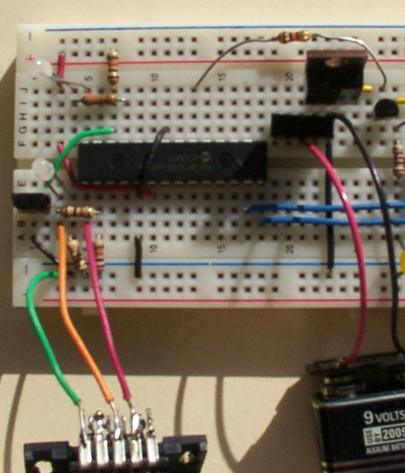
I grabbed the unregulated 9V straight from the battery, threw another PIC on the board, hooked it up, and downloaded the cloner code into John’s chip. (Uh, John, did you realize I’d be overwriting whatever program you already had in there? Sorry about that . . .) Pressed the Go button, and– . . . uh, the button popped right out of the breadboard. I’m gonna have to solder longer leads onto that puppy. Jammed it back in long enough to hit it, and voila! Run light went green (“doing something”) and programming light came on.

[INSERT PHOTO OF CHIP CLONING WITH LIGHTS]

After a while (don’t know if it was four minutes like the guide said) the programming light went off and the run light went red (idle), and it was done. I pulled John’s chip out of the breadboard and put it in an anti-static bag to bring back, put my new LogoChip into the master slot, and cloned it onto another blank chip to make sure it worked. Same deal–lights came on, blah blah–and now I have two LogoChips. W00T!


Piezo Buzzer == NOT!

I tried hooking a piezo speaker to one of the pins to make a bleebledy-bloop program like the guide’s tutorial shows, but couldn’t get any sound. When I put 5V directly across it, it does click a little, so it may just need more current than the chip is supplying. I may try setting it up with a drive transistor to see if that helps; but I salvaged it out of a microwave, so I don’t actually even know for sure that it’s a speaker. Maybe it’s a secret Klingon nucrification death device.

I busted loose a piezo beeper from my stash of dead pagers, but it had SMT solder leads that I couldn’t just jam into the breadboard, so I let it go and called it a night.

And in Conclusion . . .

LogoChips are cool.

Welcome to Technology: Art and Sound by Design

Thursday, February 2nd, 2006

This spring, I’m sitting in on a class called Technology: Art and Sound by Design, taught by John Harrison. The class interfaces engineering students with fine arts students, and microcontrollers with artistic expression. I’ve seen some of John’s cool toys, and I’m really looking forward to the things we’ll be building!

I’ve seen John for several years in his role as concertmaster of the Wichita Symphony Orchestra, so I confess to being a bit star-struck at actually talking to him and attending his class. It’s taking quite a twist of my brain to reconcile his stage presence (I’ve watched him play the solo violin in Vivaldi’s Four Seasons, for goodness sake) with his fun-loving, geeky side. Turns out he’s my age and has almost the same technology background I do–we both grew up with lots of the same microcomputers, programming assembler, writing games, etc. He diverged to music as a primary career, and I to computers.

I’m very grateful for his welcoming me into the class. He encourages my participation in discussions, in doing the projects, and in contributing to the class wiki. This should be a fun semester!