Archive for the ‘Robotics’ Category

Robot Throwdown!

Thursday, March 23rd, 2006

I was joking around with a coworker asking how soon he was going to switch a Unix server to use LDAP for login authentication instead of the local password file, and after seeing my two-wheeled balance ‘bot crash and dive yesterday, he replied:

When a two-wheeled balancing robot scoots into my office and tells me to do so!

Then after I asked whether he was willing to commit to that promise, he backpedaled and followed up with:

I sense trickery, either that or motivation to expidite the process.

Just in case I better clarify, lest some off-the-wall intrepretation of the rules takes place.

I, Garrett Marks, will enable LDAP authentication on zion for system accounts when,

A two wheeled, self powered, balancing robot enters my office under its own power (the door may be held open for the poor fella) and audibly asks me to “enable ldap authentication on Zion, please” via some sort of electronic powered sound producing system (no it can’t just hand me a post-it note). The robot must be assembled by Keith Neufeld.

And later, another caveat:

A1: The robot must be standing upright when it delivers its request.

Okay, Garrett; you’re on!

EAGLE for Circuit Design and PCB Layout

Tuesday, March 21st, 2006

I’ve been looking for circuit design and PCB layout software for a long time, and in the past couple of weeks I’ve settled on EAGLE. I’ve used it to draw up the most recent schematics here on my blog. Its key advantages for me are:

  • There’s a freeware version. I don’t do enough circuit design to justify paying a lot of money for commercial software–especially software that I haven’t got to try first.
  • It can output netlists from it circuit design module to use with other PCB layout software, and it can output Excellon drill files to use on my friend Joel’s CNC drilling machine.
  • It runs on Windows, Mac, and Linux–and I expect to use all three versions regularly.

To understand why I like it so much, though, it’s worth running through the other software I’ve used.

Electronics Workbench: Multisim and Ultiboard

I got a student copy of Multisim and Ultiboard with my electronics textbooks in 2004. I used it a lot in class, and I think it’s fantastic for doing circuit simulation. It blows me away that it’s even possible to do that level of analysis and simulation on a commodity PC, and I really appreciate Multisim for what it does.

Unfortunately, I also had a not insubstantial list of complaints:

  • The Multisim (circuit design/analysis) UI is pretty glitchy. I had a lot of trouble selecting the component I wanted to move; I’d box-select a group of components and drag them, and parts would get left behind (and disconnected); etc.
  • I had trouble getting the hang of the UI for Ultiboard, the board layout software. I don’t remember exactly what I didn’t like, but I know I gave up in frustration pretty quickly.
  • Worst, though, is that the installation uses a nodelocked license. I installed the software on two PCs in Pittsburg, and when I left, I completely uninstalled it. I’m now within the rights of my license to install it on another PC–but I’ll have to call EWB to get another install code, because I’ve installed it too many times to get a new code automatically.
    So I feel like the next time I install it, I need to be ready to put it onto one PC where I’m going to leave it forever–because how many more times can I call them and tell them (truthfully, but they have no way of knowing that) that I’m moving it to yet a different PC? The offshoot of that is that I’ll probably never install it again.

PCB123

I had used ExpressPCB (next) a long time ago, and while I was searching for it recently, accidentally installed PCB123 instead. Like ExpressPCB, PCB123 is a company that makes small quantities of PCBs for prototyping and hobbyist use, and gives away the software to design the circuit and layout the boards. I don’t even remember what I didn’t like about PCB123–I just know that it took me about five minutes to realize it wasn’t ExpressPCB and I wasn’t willing to learn to use it.

ExpressPCB

LogoChip in Altoids Tin Schematic
LogoChip in Altoids Tin Layout

I had been happy with ExpressPCB for a long time. They’re a board manufacturing house, and they figured out long ago that if they give away circuit design and board layout software, they’ll entice people to use their services.

I think they walk a delicate line trying to decide how much functionality and interoperability to put into their software–too much and people might use their software and then have boards manufactured elsewhere; too little and people will get frustrated using their tools.

In my case, despite finding their UI to be the absolute best I’ve handled, the functionality is too low, and I’ve moved away from their software. With a little more functionality, I’d still be using their software, and I’d turn straight to them when I need a board commercially produce.

First, I have to sing their praises:

  • I found the UI to be fantastic, in both the circuit design and board layout sections. The toughest operation for this type of software seems to be selecting an existing part to move, and I would almost always get exactly the part I was trying to select; it was easy to reselect a different part in the cases when I didn’t get it on the first try.
  • Their board layout software has a netlist checker, so you can see which pins need to be connected. (However, see “ratlines” below.)
  • The UI just has a good “feel” to it–everything handles very nicely.

However, its drawbacks were serious enough for me to move away from it:

  • Foremost, because the software exists entirely to get you to buy boards from ExpressPCB, it has no facility for exporting drill files. I’m drilling boards on my friend’s machine, drawing traces by hand, and etching in a plastic tank–I pose no threat to ExpressPCB’s business–but I can’t use their software to automate my homebrew process. It can’t be made to meet my needs.
  • ExpressPCB doesn’t prepopulate the PCB layout with the components used in the schematic. You have to add and label each component individually. That’s time-consuming and error-prone.
  • ExpressPCB doesn’t support ratlines indicating netlist connections. Yes, it can highlight solder pads that need to be connected–but it’s easier to lay out traces when you have ratlines indicating all of the connections that need to be made.
  • The board layout UI is a little over-eager to merge connections. I’ve had to scroll the entire board off the screen when calling up a new part to add, because with the board on the screen, the part got merged into existing traces before I could even select where the part was to be placed. Similarly, I’ve had entirely unrelated traces merged together because I was dragging a set of parts to a different area of the board, and corners of traces I was dragging (and would have rerouted as the next step) landed on top of other traces.

The biggest issue, of course, was being able to produce the interchange formats I needed–but the other issues served as cautions while looking at other packages.

FreePCB

FreePCB is a really nice-looking package, an amazing programming accomplishment from a single individual, and free of cost but not open source. I like it a lot, and I expect to use it for larger boards in the future. It’ll import component and netlists from other software, and it’s what led me to EAGLE for circuit design.

A few observations:

  • It doesn’t have any corresponding circuit design software. That’s means there’s no way to automate back-annotation when changing a design during PCB layout, and the coupling for forward updates isn’t as tight as with some of the other packages.
  • It’s extremely tedious to lay out a board from scratch without an accompanying parts list from a circuit design package. FreePCB is intended to be used in conjunction with circuit design software, and I’d want to use it that way most of the time. However, I was trying to lay out a one-component, two-connector board without having drawn the schematic, and found it prohibitively difficult to do.
  • It has ratlines, a nice feel, decent export capabilities, etc. It was designed by an engineer–it was made to work well.

EAGLE is a little smoother for me to use, but the free version has some restrictions that I may eventually run into. When I do, I plan to use FreePCB for those boards.

Hand-Created Drill Files

For a 2″ x 2.5″ board with a PIC microcontroller, RJ-45 connector, LED array, lots of sockets, and supporting passives; for the one-component board I mentioned above; and for a couple of other boards I’ve worked on since then; I’ve drawn the circuit (and sometimes the PCB) in one package or another, and then laid out the drill file by hand. It’s not hard–key in a zillion (x,y) coordinates, plot the file in gnuplot to make sure it looks right, use a small Perl script to translate to rudimentary Excellon code, and drill it.

It’s a dumb way to have to do things, but it got me a drill file that I couldn’t get out of ExpressPCB, and it got me a layout that I didn’t have time to figure out how to do in FreePCB. I’d rather not make a lifestyle of it, though.

EAGLE

ADXL202E Carrier Board Schematic
ADXL202E Carrier Board Layout

Which brings me to EAGLE, the software I think I’m going to be using for a long time to come. It outputs the formats I need, it runs on all the OS platforms I use, and a slightly restricted version is available at no cost. The freeware limitations won’t impact me for quite a while: only one-sheet schematics, only two-layer PCBs, and PCBs no larger than 4″ x 3.2″. I’ll hit the last one first, and I’ll use FreePCB for layout when it happens.

I do have a few complaints about the UI:

  • It’s often very difficult to select an onscreen part to move to a different location. I’m starting to resort to drawing a select box around the interior of the part in order to select it and nothing else; I much prefer the click-click-click to cycle through overlapping parts. I think there’s a right-mouse trick to cycle in EAGLE, and I need to learn it.
  • Speaking of right-mouse, too much of EAGLE’s functionality depends on it. I use the right mouse button nonstop when I have one, but my PowerBook doesn’t.
  • The screen doesn’t automatically refresh objects when other objects have been covering them and are removed, at least not in the X11 versions. Yes, I can hit F2 to redraw the screen, but it’s often really messed up until then.
  • EAGLE seems to have serious problems performing unintended merges during component rotation operations–I have PCB traces that get stuck together and I have to reroute by hand. Worse, that situation seems to corrupt the netlist, because it changes the ratlines. I’m stuck with leftover ratlines that disagree with their traces, and no way to correct them. This is very problematic.

But mostly gratitude at finally finding software that does so many things right:

  • Pretty good coupling between the schematic and board layout sections, including prepopulating components and ratlines
  • The ability to export a netlist to use in a separate board layout program
  • The ability to export drill files in Excellon format to drill my own holes

LogoChip and PWM: Bidirectional Motor Speed Control

Tuesday, March 21st, 2006

Early last week, I was working on expanding my PWM motor speed control to be able to reverse directions. I had the PWM output from my LogoChip’s PWM subsystem, and I wanted to add another line to indicate whether to spin the motor forward or backward.

Because I’m using the 754410 motor driver chip, I need to apply the PWM signal to the pin corresponding to the direction I want the motor to turn, and keep the other 754410 input pin grounded. That means I needed to translate from (speed, direction) to (move forward, move backward). I have lots of digital logic chips lying around, so I knew I could put something together.
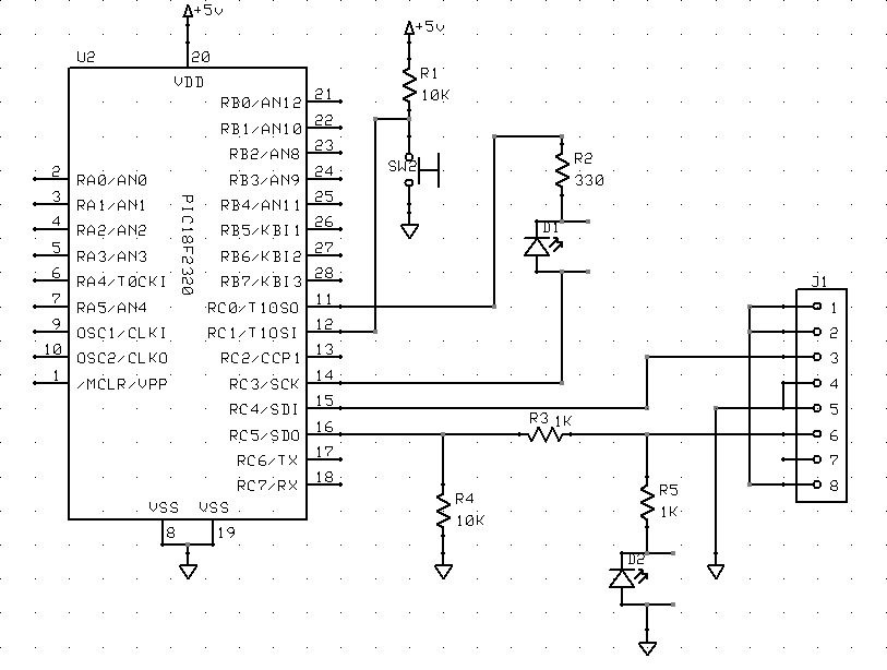
Ideal Schematic

Ideally, if I had all the gates I wanted on a single chip, it’s this simple:

Ideal Motor Direction Control Schematic

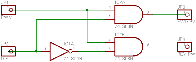
(Pardon the truncated labels on the right side–EAGLE did that for me in the PNG export.)

I’m using a direction of 1 to mean forward and 0 reverse. So here’s what the schematic means:

  • If the PWM speed signal is on and Direction is 1 (forward), activate the Forward output.
  • If the PWM speed signal is on and Direction is 0 (reverse), activate the Reverse output.

I could have done this with a 74*08 quad AND gate and a 74*04 hex inverter, but that’s two chips. It offends my sensibilities to use two chips when one would suffice, plus I don’t have a lot of room to spare on my LogoChip breadboard. So I looked for something better.

74LS138

I was looking for a chip with a data input and address input(s) to select which output line the data was routed to, and the closest I could find was the 74*138. The ’138 is 3-to-8 decoder/demultiplexer, meant to decode three lines of an address bus into eight enable inputs for memory or other chips: You supply a three-bit address to its inputs, and it activates the corresponding one of its eight outputs.

This wasn’t exactly what I needed, but there’s a trick I figured I could use. I applied the Direction signal to an address input, to select which output would receive the PWM signal; then I applied the PWM signal to one of the enable inputs. In theory, that means that both outputs would be inactive any time the PWM speed signal was off, and the appropriate output would be active when the PWM speed signal was on.

Motor Direction Control with 74LS138

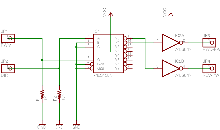
Unfortunately, EAGLE’s circuit symbol for the ’138 is a block diagram that doesn’t illustrate the internal logic, but here’s what’s going on. Direction is applied to address line A, which will select output Y1 (Forward) when Direction is 1 (forward) and output Y0 (Reverse) when direction is 0 (reverse). And the PWM speed signal is applied to active-high enable line G0, to activate the appropriate output whenever it’s high. The other enable lines are active-low, so they’re tied to ground to be active all the time.

But you’ve probably noticed that it’s still a two-chip design–there are two inverters off to the right. Unfortunately for this project, the ’138′s outputs are active-low. Most memory chips have active-low enable inputs (it makes it easier to gang together open-collector selection circuitry), so naturally the ’138 provides an active-low output. In order to get the active-high signals that I wanted to feed into the 754410 motor driver chip, I had to invert the ’138′s outputs, and that meant adding another chip. I did build and test this circuit as a proof of concept, but I still wasn’t satisfied, and kept looking.

As a bit of an aside–I could have used active-low signalling to drive the 754410. It’s an H-bridge driver chip, so it powers the motor whenever it has different inputs. When the inputs are the same–low or high–the motor doesn’t run. However, I’m guessing there’s slightly more power consumption when both inputs/outputs are high, and I wanted it to draw as little power as possible in the quiescent state, so I was determined to come up with a circuit that would provide active-high signalling.

One other note–I tied both inputs to ground with pull-down resistors. As long as the LogoChip is providing outputs, these are irrelevant–but when the LogoChip first powers up, its ports are configured as inputs and don’t provide a valid TTL signal to the ’138. The motor was freaking out (that’s the technical term) when I’d reset the LogoChip, so I added the pull-downs for power-up sanity.

74LS153

The 74LS153 is my final, one-chip solution. It’s a dual 4-line to 1-line data selector/multiplexer, meant to do exactly, uh, the opposite of what I need: It picks which of four inputs to send to the output. But that’s okay–there are two selector/multiplexers in one package. That means I can use one multiplexer to select whether the PWM or nothing goes to the Forward output, and the other to select whether nothing or the PWM goes to the Reverse output. Looks a little somethin’ like this:

Motor Direction Control with 74LS153

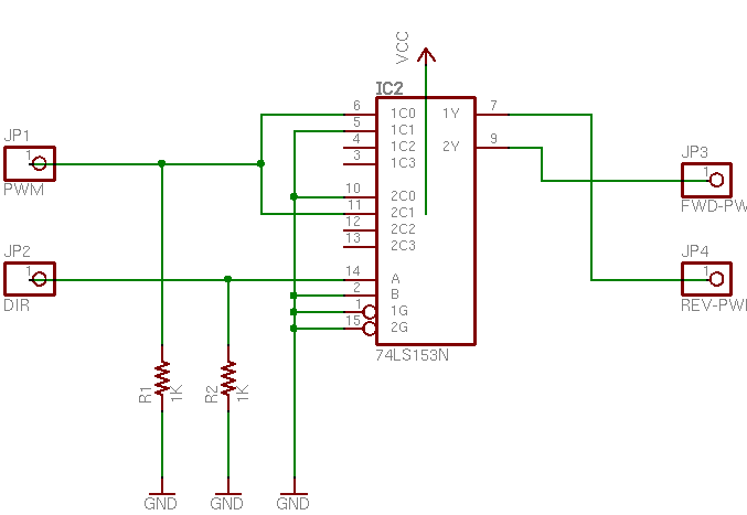
Again, EAGLE renders the ’153 as a block without exposing its inner workings, so explanation is in order. Inputs A and B are the address lines (think A0 and A1) to select which data input will be delivered to the output. Note that A and B select for both multiplexers at the same time, so I don’t have to wire to separate address lines for the two multiplexers. Input B (address line 1) is tied to ground because I always want it 0–I’m only working with the first two possible inputs. And the active-low enable inputs are tied to ground, because I always want the chip enabled.

The first selector has the PWM signal at its 0 input (1C0), ground at its 1 input (1C1), and its output (1Y) feeding the Reverse driver. So when Direction is 0 (reverse), the first selector will pick input 0 (PWM) and feed it to the Reverse input of the motor driver. When Direction is 1 (forward), the first selector will pick input 1 (ground, or nothing) and feed it to the Reverse input of the motor driver.

Likewise, the second selector has ground at its 0 input (2C0), the PWM speed signal at its 1 input (2C1), and its output (2Y) feeding the Forward driver. When Direction is 1 (forward), the second selector routes input 1 (PWM) to the Forward motor drive pin. When Direction is 0 (reverse), the second selector routes input 0 (ground) to the Forward motor drive pin.

Because human minds are forward-centric (there’s a very interesting section of linguistics that studies which word out of pairs of opposites has connotations of dominance: forward/reverse, up/down, hot/cold, etc.), it would seem to make more sense to use the first selector for the forward drive and the second selector for reverse. But I wanted Direction == 0 to activate the first selector and Direction == 1 to activate the second, and because I made Direction == 1 for forward, it worked out like this.

I added pull-down resistors again–different values this time, based on the datasheet and application notes. And the circuit works, in a single chip! Yeah, the ’153 is overkill for this application–but I can’t find a simpler single chip that’ll do the job. I could do it with a PAL and have room left over for other tasks; but in the absence of a need for other logic in this project, that’s even more overkill.

Finis.

LogoChip: PWM Motor Control

Thursday, March 9th, 2006

Built-In PWM

A while back, John sent me some code that he and Tom had been using to test the pulse-width modulation (PWM) capabilities of the hardware underlying the LogoChip. I read through the PIC18F2320 datasheet over the weekend and learned how it does PWM; and between John and Tom’s sample code and the information in the datasheet, tonight I got a motor running at variable speed under software control.

To use the PIC’s PWM, you configure the Timer 2 counter for the modulation frequency (period, actually), then set the output port into PWM mode and configure the duty cycle. Sounds simple; it’s really just a matter of finding all the control registers and the proper bits. Because the PWM is implemented in the chip’s hardware, it keeps running at the last-set duty cycle (== motor speed) even if you’re doing something else or your program stops running, so you can set and forget.

I’d like to measure the PWM output frequency and confirm what the Timer 2 counter and prescalar are doing, but my frequency counter is giving me weird results and I have no idea how far out of calibration my scope is, so that’ll have to wait for another day. When I hook a speaker to the output, it sounds well below 440Hz, but the frequency counter is trying to tell me it’s 2+kHz. Feh.

Huh, when I calculate the frequency (if I’m doing it right), I come up with ~2.4kHz. My speaker is a piezo and it sounded funny, so maybe that’s outside its range and the frequency counter was right on?

The Code

After I got over the excitement of just getting it to work at all, I wanted it to do more than let me manually set a speed for my motor, so there are a couple of extra procedures at the bottom (pwm-speedup and pwm-slowdown) to ramp the speed from slow to fast and back down to slow. They add to the code length, but they’re not critical for implementing PWM.

Here’s the program:

Here’s the code:

;   Keith Neufeld
;   08-Mar-2006
;
;   LogoChip program to demo motor speed control with PIC PWM output.
;   Uses PWM channel 1 on port C2.  Duty cycle values determined with
;   NPN transistor driver with 9V motor supply.

constants [
    [CCP1CON $fbd]                      ;   capture/compare/PWM 1 control reg
    [T2CON $fca]                        ;   timer 2 control register
        [TMR2ON 2]                              ;   timer 2 enable bit
        [T2CKPS1 1]                             ;   timer 2 prescale bit 1
    [CCPR1L $fbe]                       ;   C/C/P 1 register low byte
    [PR2 $fcb]                          ;   timer 2 period register

    [pwm-port-ddr portc-ddr]            ;   PWM 1 outputs on port C2
    [pwm-bit 2]

    [period 255]                        ;   default timer period to use
    ;[low-duty 110]                     ;   lowest duty cycle for my motor to
    [low-duty 10]                       ;   start from a stop
    [high-duty 255]                     ;   highest possible cycle
]

;   Initialize PWM by configuring timer 2 for PWM period and enabling PWM mode.
to pwm-init
    clearbit pwm-bit pwm-port-ddr       ;   set PWM port to output

    ;write T2CON 6                      ;   set timer 2 on, prescalar 16
    setbit T2CKPS1 T2CON                ;   set timer 2 prescalar to 16
    write PR2 period                    ;   set timer period highest possible
    setbit TMR2ON T2CON                 ;   turn on timer 2

    write CCP1CON 12                    ;   set PWM mode
    ;write CCPR1L 128                   ;   set 50% duty cycle
end

;   Set PWM period and duty cycle.
to pwm-set :period :duty
    write PR2 :period                   ;   set timer period
    write CCPR1L :duty                  ;   set PWM duty cycle
end

;   Disable PWM by shutting off timer 2.
to pwm-off
    pwm-set 0 0                         ;   disable PWM by setting duty cyc to 0
    clearbit TMR2ON T2CON               ;   and turn off timer 2
end

;   Enable PWM and ramp up to highest speed at :increment / 255ths
;   per 1/10 second.
global [duty]
to pwm-speedup :increment
    setduty low-duty
    pwm-set period duty
    repeat ((high-duty - low-duty) / :increment) [
        wait 1
        setduty duty + :increment
        pwm-set period duty
    ]
    setduty high-duty
end

;   Enable PWM and ramp down from highest speed at :increment / 255ths
;   per 1/10 second.
to pwm-slowdown :increment
    setduty high-duty
    pwm-set period duty
    repeat ((high-duty - low-duty) / :increment) [
        wait 1
        setduty duty - :increment
        pwm-set period duty
    ]
    setduty low-duty
end

Got Beep

Monday, February 6th, 2006

Read the Manual, Stupid

Last week when I was trying to get the piezo buzzer to work with the LogoChip, I was in such a hurry to get to the sound that I skipped this part of the instructions:

Upon powering up, all of the user accessible pins on the LogoChip are configured as “inputs”. . . . Therefore, for the exercises in this document, we would like to always have all of the portb pins configured as outputs. . . . This can be done by creating the following special powerup procedure.

to powerup
write portb-ddr 0 ; turns all of portb into outputs
end

Last night when I soldered pins onto the piezo buzzer from the pager, plugged it into the LogoChip, and still couldn’t get sound out of it, I knew something was up. Finally it dawned on me that I didn’t know which way the ports were configured at boot, and looked at the getting started guide closely enough to find the section I quoted above. With the ports configured as outputs, it beeps just fine. Duh.

Beep Volume

I’m surprised at how quiet the beep is running on 5V, compared to how obnoxiously noisy the beep is in a pager on 1.5V. I changed back to the beeper from the microwave and it’s a little louder, but not much. Is the 1.5V in the pager really getting stepped up somehow? Tiny transformer, or voltage multiplier? Maybe I just need a driver transistor; I guess some experimentation is in order.

Beep Code

Making a beep was cute and simple, but booooring, so I made a little warbly sound.

to powerup
        write portb-ddr 0            ;   set port B to output at power-up
end

to startup
        warble 3                     ;   "warble" three times when the Go button is pressed
end

to click-on
        setbit 0 portb
end

to click-off
        clearbit 0 portb
end

to delay :n
        repeat :n [no-op]            ;   waste time by doing nothing, several times
end

to note :period :duration            ;   play a note of a given pitch for a given duration
        repeat :duration [           ;   repeat as long as requested
                click-on             ;   make a sound
                delay :period        ;   wait a little bit
                click-off            ;   make another sound
                delay :period        ;   wait another little bit
        ]
end

to warble :times        ;   make a warbly noise several times
        repeat :times [
                note 2 200           ;   make a low-pitched sound
                note 1 200           ;   make a higher-pitched sound
        ]
end

Of course, downloading a routine named powerup doesn’t automatically invoke that routine (unless you reboot the chip), so I invoked it manually from the console. Having done that, the routine makes a nice little warbly noise any time you type warble # at the console, or press the “Go” button on the circuit board.

Another thought: Since note‘s duration code loops around calls to the click-on, click-off routine, which calls delay to set pitch, the duration is actually impacted proportionally to the pitch of the note. It’d be interesting to rewrite the duration code to take input in ms (or seconds) and check timer to see when we’ve played the tone for long enough.

Pitches and Timing

If the code makes sense to you, then you’ll notice that I’m calling the delay routine with the second-shortest and shortest possible delays–twice and once through the loop. With delays of 2 and 1, the second pitch should be an octave higher than the first (twice the frequency)–but in practice, the one sound is only about a minor third higher than the other. That means that the overhead of calling the delay procedure is much higher than the delay of running once through a timing loop around a no-op.

Here’s the math: a minor third corresponds to a frequency difference of the fourth root of 2 (in equal-tempered tuning), whereas an octave is a factor of two. So if there were no overhead for calling the procedure, then the respective frequencies and periods would be simple doubles of each other:

f2 = 2f1
p1 = 2p2

But in practice

f2 = 4√2 f1
p1 = 4√2 p2

Let’s define tcall as the duration of the function call overhead (which should be constant) and tnoop as the duration of one trip through the loop in the delay procedure, including both loop overhead and the no-op operation (which we’re told is 13ms). (This ignores the fact that loop overhead will be slightly different when repeating and when exiting, but I suspect that the difference is small enough to be irrelevant. If anyone wants to check, I can measure frequencies for more delay values and give you equations in three variables . . .)

p1 = tcall + 2tnoop
p2 = tcall + 1tnoop

Then substituting back into the period relationship

p1 = 4√2 p2

tcall + 2tnoop = 4√2 (tcall + tnoop) = 4√2 tcall + 4√2 tnoop

2tnoop4√2 tnoop = 4√2 tcall – tcall

(2 – 4√2) tnoop = (4√2 – 1) tcall

tcall / tnoop = (2 – 4√2) / (4√2 – 1) ≅ 4.3

So if I did all that right (and I confess I ‘m pretty rusty), the overhead of calling delay is a little more than four times the delay of one trip through the no-op loop. Hmph.

Regardless of the relative values, the actual frequencies aren’t particularly high–higher than 440Hz, but well within the limits of my hearing. (I should test them tonight with my frequency counter.) That’s a bit disappointing for a 5Mhz-clocked chip running flat-out in a busy wait.

I thought about clocking the chip up to 40MHz per the instructions in the getting started guide (8x the clock speed = 3 octaves higher = outside the limits of my hearing), but I didn’t order the crystal and I didn’t have two 10Mhz crystals in my parts bin. Shucks.

I just talked to John, and he said that he and Tom McGuire were able to produce higher sounds using the chip’s built-in PWM. Not bad for a hack, but I wanted to use both channels of PWM for motor control. Think I need me a crystal.

Atmel/AVR Butterfly?

Friday, February 3rd, 2006

Whilst searching for the application note on using the native UART from the LogoChip (which doesn’t seem to exist), I ran across this discussion board about microcontroller programming from OS X.

What caught my eye was the mention of the Atmel/AVR Butterfly. John Harrison has been touting the Atmel micros to me, but mainly mentioning the GNU toolchain. The Butterfly is an evaluation board with an Atmel micro on it, a 100-segment LCD, mini-joystick, light and temperature sensors, speaker, RS-232 level converter, and headers to access all the ports.

But wait–there’s more! No separate device programmer necessary–it can download code through its RS-232 port! Now how much would you pay?

But wait–there’s more! All that comes on a board the size of . . . a table? Nope, smaller! A breadbox? Nope, smaller yet! A nametag! That’s right, folks; all that functionality on a board small enough to clip onto your shirt!

Now how much would you pay?!! $80? $130? Nope, less than that.

$20.

Twenty. Freakin’. Dollars.

Available from Digi-Key.

Starting up the LogoChip

Thursday, February 2nd, 2006

Introduction to the LogoChip

A lot of the work in the Technology: Art and Sound by Design class will revolve around the LogoChip, a PIC18F2320 microcontroller (~$8 in 28-pin DIP) with scads of I/O pins and a Logo byte-code interpreter. (The Logo code is compiled on a host computer and downloaded to the chip.) The getting started guide gives examples to flash LEDs, beep piezo speakers, and move Lego motors.

The chip looks very promising for my own hobby use as well. I’ve been intending to dive into microcontrollers for a long time, and always assumed it’d be PICs. I have a BASIC Stamp (and a separate PIC) on my SumoBot, so that’d be one entry into microcontroller programming; but the LogoChip appears to be even easier to get into.

I’d been planning to follow up to my tilt sensor project with a PROM-based controller, but a little logic tells me that I’d need to quantize the sensor’s PWM output into at least 32 slices to get acceptable motor behavior, and that’s a lot of work to do in discrete logic. I’m afraid I’d overload my small motor just with the weight of the TTL DIPs required to do that. I had really wanted to build a motor controller without a microcontroller, just to show myself that it could be done, but I think it’s time to move on.

Building Circuits

The last two nights, I’ve breadboarded the LogoChip circuit, got it communicating with a host computer, and successfully built the cloning circuit to program the LogoChip code into the blank PICs I bought. The road to success was paved with annoying obstacles, though.

The getting started guide gives a schematic and step-by-step instructions to lay out the supporting circuitry on a breadboard. Of course, I’m stingy with space (I want as much room left over for other components to experiment with), so I managed to collapse the circuitry into the smallest possible amount of space. I saved .4″ over their design! Woo-hoo!

LogoChip on Breadboard

But I built and tested it using my bench power supply, forgetting that I was planning to power it with a 9V battery and 7805 voltage regulator. After I had it all working, I didn’t have room to add the 7805, so I had to stick it down at the other end, move the power switch, etc. ERROR.

LogoChip and 7805 Voltage Regulator on Breadboard

Also, the guide’s schematic for the serial interface disagrees with its visual layout instructions, and the schematic is incorrect. The indicator LED and its current-limiting resistor need to attach directly to DB-9 pin 3 (the host’s TD / chip’s RD), not to the chip’s C5 (pin 15) as shown in the schematic. When attached to C5, it appears to pull down the signal too hard, and I couldn’t get serial communications to work.

[INSERT CORRECTED SERIAL INTERFACE SCHEMATIC HERE]

And, OBTW, the LogoChip goes into the circuit UPSIDE DOWN. That’s right, engineers–don’t try to insert it with pin 1 in the usual position, ’cause that’s not the orientation they chose to use. (???!!!)

I only did that once.

Mac Interface Troubles

The guide points to the files needed to install the LogoChip Desktop Software, but doesn’t give much information about what to do with them. I’ve written more detailed instructions on the class wiki. Strangely, the Java serial communications driver seems to require Classis (OS 9) support in order to install correctly–that’s the only difference I can find between my work desktop computer (where it installed and ran fine) and my notebook computer (where it didn’t). I still plan to get this working on my notebook somehow, so watch the wiki for updates.

Cloning LogoChips

The LogoChip has a cloning process to copy the Logo firmware onto another PIC. Because you can use this to get the firmware onto a chip without a PIC programmer (which I don’t have and haven’t built yet), I ordered blank chips from Digi-Key rather than preprogrammed LogoChips from Wellesley, and John loaned me one of his chips to clone.

The clone routine is a program that has to be downloaded to the LogoChip, not a permanent part of the firmware, so I couldn’t clone until I had the serial communications working. John loaned me the chip Tuesday and I promised to have it back today (Thursday), so that put some pressure on me to get the serial issues debugged. I ended up using my wife’s Windows machine last night for the programming.

Since I’m powering my circuit from a 9V battery instead of the 4xAA 6V pack recommended by the guide, I was curious whether I’d have to add another battery for clone circuit’s programming voltage, or whether I could get away with 9V. Googling for PIC18F2320 programming voltage led me to Microchip’s programming specification, which has an AC/DC Characteristics chart waaaay at the bottom which gives a range of 9.00-13.25V for high-voltage programming. Shiny!

I grabbed the unregulated 9V straight from the battery, threw another PIC on the board, hooked it up, and downloaded the cloner code into John’s chip. (Uh, John, did you realize I’d be overwriting whatever program you already had in there? Sorry about that . . .) Pressed the Go button, and– . . . uh, the button popped right out of the breadboard. I’m gonna have to solder longer leads onto that puppy. Jammed it back in long enough to hit it, and voila! Run light went green (“doing something”) and programming light came on.

[INSERT PHOTO OF CHIP CLONING WITH LIGHTS]

After a while (don’t know if it was four minutes like the guide said) the programming light went off and the run light went red (idle), and it was done. I pulled John’s chip out of the breadboard and put it in an anti-static bag to bring back, put my new LogoChip into the master slot, and cloned it onto another blank chip to make sure it worked. Same deal–lights came on, blah blah–and now I have two LogoChips. W00T!


Piezo Buzzer == NOT!

I tried hooking a piezo speaker to one of the pins to make a bleebledy-bloop program like the guide’s tutorial shows, but couldn’t get any sound. When I put 5V directly across it, it does click a little, so it may just need more current than the chip is supplying. I may try setting it up with a drive transistor to see if that helps; but I salvaged it out of a microwave, so I don’t actually even know for sure that it’s a speaker. Maybe it’s a secret Klingon nucrification death device.

I busted loose a piezo beeper from my stash of dead pagers, but it had SMT solder leads that I couldn’t just jam into the breadboard, so I let it go and called it a night.

And in Conclusion . . .

LogoChips are cool.

PWM Motor Control with a ROM

Tuesday, January 17th, 2006

Here’s my next plan for motor control: Digitize the ADXL’s PWM signal into sixteen time sections (four left and four right) and use the resulting code and a PROM to generate a new PWM controlling the motor.

ADXL202 with PROM for Motor Control

More details to be added later.

Tilt Sensor and Motor Drivers, Take I and II

Sunday, January 15th, 2006

After getting the PLL locked onto the signal from my ADXL202 tilt sensor and deriving separate left and right signals from it, I hooked it to the SN754410 H-bridge driver and wired up a motor salvaged from a toy car.

My goal is to control the motor’s direction using the H-bridge and its speed using pulse-width modulation (PWM)–the same signalling technique the sensor uses to indicate the magnitude of its tilt. I’d like the speed control to be proportional to the degree of tilt, so that a small tilt results in a slow correction from the motor, and a large tilt results in a faster correction.

With PWM speed control, the power to the motor is turning on and off at a fixed frequency, high enough to be irrelevant to the motor’s motion, but low enough not to cause problems with the induction of the motor’s windings. (Mine seems to be running at about 140Hz.) To make the motor go faster, leave the power on for a longer portion of each cycle before turning it off; to make it go slower, leave the power on for a shorter portion of each cycle.

In my first attempt, I wired the motor for locked antiphase driving. This control method constantly supplies power to the motor, but rapidly reverses its direction. To make the motor go faster forward, supply forward power for more of the time and reverse power for less of the time. This obviously consumes a tremendous amount of power, but also provides strong control over the motor’s behavior. It could be useful in getting a robot to stand still on a hillside, or hold its ground in a competitive setting without specifically trying to advance.

In my case, it just makes the motor vibrate. I suspect I’m not really supplying enough power to make it work, and the motor never does more than jerk a bit as I tilt the sensor toward its extremes. It was a nice idea–had it worked, it would have meant I could wire the sensor output directly into the motor driver’s input with no additional circuitry–but it just wasn’t meant to be.

For my second attempt, I used the left and right signals that I derive from the sensor and the phase-locked, 50% duty cycle signal, and wired them to the H-bridge inputs. Theoretically, this should have worked better than the locked antiphase control–with only one input active at a time, I should get more oomph out of the motor, and it might actually turn a bit instead of just jittering. Sadly, this still wasn’t the case. Apparently with this motor and only a 9V supply, 0-25% duty cycle isn’t enough to get it going, and certainly not enough go make it ramp up speed slowly with a slowly-increasing signal.

Those two methods were essentially freebies–all of the signals were available using parts I’d already wired onto the board. For my third attempt, I added a 74LS279 S-R latch, a logic device that remembers whether it has most recently been set (S) or reset (R) and holds its output accordingly.

I didn’t get very far in my experimentation before abandoning that line of pursuit as well. My thought was that I could use a master S-R latch to remember whether the motor was supposed to be turning forward or backward, and slave S-R latches to activate from the start of the duty cycle to the end of the “rightness,” or from the start of the “leftness” to the end of the duty cycle. This would change the effective duty cycle of the motor control from 0-25% to 0|50-75%.

The first complication was that my signal (sensor) and reference (PLL) don’t seem to be exactly in phase, or that the phase delay of negating one or the other is noticeable. When I view the derived left and right signals closely on my scope, I see a tiny spike at the start of each master duty cycle. Those spikes set and reset the forward-backward latch semi-randomly, preventing me from using this method without getting my phase timing more tightly calibrated than I want to have to rely on.

So just to test whether any part of the method was viable, I set up the left-tilted slave S-R latch to set (activate) as soon as the left signal is detected (remember, the earlier it is, the further left it’s tilted), and reset (deactivate) at the end of the master duty cycle. This gave a duty cycle of 50-75% for my S-R output, which I then fed into the H driver.

It was closer to what I wanted, at least; but not there yet. At 50% duty cycle, the motor is already running pretty fast for a small correction; and at 75% duty cycle, it’s perceptibly faster, but not as much so as I’d like. The real flaw is that even if this method worked, when it was nearly level, it’d oscillate between 50% forward and 50% backward. That’s a lot of action for a rig that’s already almost balanced.

I know, I know; the easy way to deal with this is to read the sensor with a PIC and set the motor behavior however I want in software. I’ll get there eventually. For now, though, I’m really hoping I can get this to work in discrete circuitry. Partly I’m interested in doing it for the experience (like building my own H-bridge board); partly I like thinking of this circuit as a low-level reflex, and doing it in software would make it feel more like a conscious action.

I’ll keep puzzling over more ways to do it in hardware–but I’m afraid it’s going to come down to inventing a linear pulse stretcher, which wasn’t on my calendar for January.

H-Bridge Motor Drivers

Sunday, January 15th, 2006

If you want to reverse the direction of a DC motor, how would you do it? One of two ways:

  1. Change the positive voltage to a negative voltage
  2. Swap the two power leads

The first method is the simplest, but requires a dual-ended power supply–two sets of batteries, or a more complex circuit to split the voltage or generate the negative voltage from the existing positive. Either way adds overhead to the power supply.

The second method turns out to be the easiest to implement in practice, although it’s a bit tricky in an all-electronic solution. If you’re using relays to control the motor, you just use a DPDT relay with an off position, wired like so:

[insert relay schematic here]

To make the motor go forward, activate the FWD coil; to make it reverse, activate the REV coil.

The trick comes when implementing this in electronics. Most electronic switches (transistors) only pass electricity in one direction, so you can’t use a single switch to change the direction of current flow. The solution is an H-bridge, a set of four power transistors arranged like the upper and lower legs of an H, with the motor wired across the middle.

[insert H-bridge schematic here]

To make the motor turn forward, activate transistors 1 and 4. To make it reverse, activate 2 and 3. To burn out your transistors and power supply, activate 1 and 2 or 3 and 4.

On my CD-bot, I built an H-bridge from scratch out of (salvaged) small-signal, bipolar transistors. I wanted to do it from the ground up once, to know that I could. I also wanted to honor the goal that everything in the bot was made from salvaged materials, and I’ve never salvaged an H-bridge (as far as I know).

[insert picture of CD-bot motor driver board and 754410]

Since then, I’ve discovered the SN754410 quad half-H driver, which I purchased from Acroname. It’s a 16-pin DIP that provides four half-H-bridges, i.e. two complete bridges. It’s a piece of cake to use; and because one input controls an entire side of the H (transistors 1 and 2 or 3 and 4 in the diagram above), you can’t short it out with a simple mistake in the control logic. It’s a wonderful chip, I’m delighted to have found it, and I wonder why it’s not mentioned more often.