Archive for the ‘LogoChip’ Category

LED Clock: LED Numbering Order

Thursday, June 22nd, 2006

The Question

This totally doesn’t matter, and OTOH it’s a little aesthetic touch I want to get right. What should be the order that the individual LEDs are numbered within one character?

This impacts two things: circuit layout and LED test patterns. I’m ready to start laying out the circuit, which is why I’m thinking about it now. I’ve thought about LED test patterns, which is why I’m thinking about it at all.

The LED drivers shift in their data bit by bit, while shifting their current contents out in the same fashion. So if you want to enter 11111111 into a driver currently containing 00000000, it works like this:

00000000 ← 11111111
00000001 ← 1111111
00000011 ← 111111
00000111 ← 11111
00001111 ← 1111
00011111 ← 111
00111111 ← 11
01111111 ← 1
11111111

The Impact

This means it’s very easy to do moving marquee type of effects by shifting a single 1 bit or a short row of 1 bits through a display:

0000000000000000
0000000000000001
0000000000000011
0000000000000111
0000000000001110
0000000000011100
0000000000111000
0000000001110000

Just shift a few 1 bits into the register, then keep clocking it and latching the input register to the output register on every clock cycle.

Now, granted, the 6276 is so fast compared to human vision that I could shift in an entirely new pattern from scratch, then latch it, way faster than you could possibly see. But there’s a certain elegance in taking advantage of the driver’s architecture for the design of a test pattern. So I’d like to arrange the LEDs to do just that–make a pleasing test pattern when activated in order from D0 through D30. (Not a typo–only 31 LEDs in the design.)

The Proposal

Here’s what I’ve come up with, drawn a couple of different ways:

LED Order LED Order

The test pattern starts in the middle of the digit, loops through the upper half clockwise and the lower half counterclockwise, springs off the right edge to the top of the colon, and drops down into the period. The possible issues are:

  • Is this even the right kind of pattern to do?
  • Is that the right starting point, in particular with respect to the extra LED inserted in the lower half to smooth out the 2?
  • Is it right to skip the middle-right LED on the way down, and leave it for the end before jumping up to the colon? Or should it be included on the way down, and skipped on the way to the colon?

I’m open to suggestion, but I’m also afraid that it’ll be hard to evaluate the visual smoothness of the effect for sure until a digit is prototyped–and I can’t prototype on a breadboard; it’ll require a custom PC board to do it. I guess if I were sharp enough with computer animation, it shouldn’t be that hard to do this in software; but at this point, I’m not sure I’m up to it. Maybe I should pull out my old C-64 . . .

LED Clock: Enough Controller Pins?

Wednesday, June 21st, 2006

Last night, while programming the LogoChip A6276 interface, I started to become concerned about having enough LogoChip pins to connect to everything I want to wire up to make the clock work. So I just did a quick sanity check to see whether I’ll have enough pins, or whether I need to double up digits together.

Here are the LogoChip pins:

Available Pins
A0 – A2
A3 – A5 ?
B0 – B7
C2
C6 – C7

I’m not sure whether A3 – A5 are available or not. They’re ghosted (grey) on the LogoChip sticker, and I’m not sure why. But because of that, I think I didn’t provide sockets for them on my Curiously Strong LogoChip, which may pose challenges while prototyping. Additionally, A0 – A2 didn’t work for driving the 6276, so maybe not even all of the available pins will work.

Anyway, here’s a tentative pin assignment.

Chip Lines Count Possible LogoChip Lines
A6276 LED driver serial data in
clock
latch (each character)
2
.
6-8
A0 – A1 (didn’t work)
   or B0 – B1
B0/2 – B8
Dallas clock chip data
clock
enable?
2-3 A0 – A2 (didn’t work for A6276)
PC serial port? TD
RD
2 C6 – C7

[Ewww, I don't like what the WordPress stylesheet does to the table text alignment.]

Looks like everything should work out, assuming that I can use all the pins the way I intended. In fact, if the clock is only six digits, I can use B0 – B1 for the 6276 data and clock lines and B2 – B7 for the digits’ latch lines, fitting the entire display driver into one I/O port. Tidy.

The Dallas timekeeping chip will need either two or three pins, depending on whether I use the DS1340 with I2C or the DS1302 with “simple” three-wire interface.

The LogoChip already connects to the PC’s serial port on pins C4 and C5; however, receiving data halts a running program. That means that while uploading control data to the LogoChip, although the real-time clock chip would continue to keep time, the display would freeze and stop updating; and that every data transmission would need to be followed by a command to restart the display program.

Since I may want to be able to send updates to the LogoChip while it’s operating (time corrections, commands to change display mode, etc.), I’m thinking of using the PIC’s built-in UART on C6 and C7 for run-time serial communication.

Anyway, the bottom line is that as long as I can figure out how to use the A port lines for digital I/O, and as long as we’re only making a six-character clock (HH:MM:SS without .TH), there are enough lines. Good deal.

LED Clock: Programming the A6276 LED Driver

Tuesday, June 20th, 2006

Banging Bits

I got the LogoChip controlling the A6276 tonight. I programmed from the bottom up, writing code to bang the bits first, and ending up with . . . not much more than code to bang bits. It’s really pretty easy–put the bit on the line feeding the serial data input, strobe the clock line (active high), and when you’re ready strobe the latch line (also active high) to copy the data to the output register.

I started out using pins A0 – A2 for the control lines, and for some reason I still haven’t figured out, they didn’t work. I could set the data bit (A0) high; but every time I toggled the clock line (A1), the data line fell low again, preventing me from shifting a 1 into the input register. Huh?? When I moved the lines to B0 – B2, they worked fine without any other changes to the code. Huhuuuhhhh?????

Strobing Clock and Latch Lines

Given that the 6276 can shift data at 10Mhz, the LogoChip PIC is running on its internal 10MHz oscillator, each PIC operation takes at least one clock cycle, and each Logo instruction probably takes several PIC operations, I should be pretty safe toggling the clock and latch lines high on one instruction and low on the next without a delay in between. I did test with mwaits in between, but it really didn’t make any difference except to slow it down. I guess conceivably I could see problems when I’m trying to shift real data later, so I’ll keep it in mind.

The Code

Here’s what I ended up with:

  • a6276.txt – Program to control Allegro MicroSystems A6276 LED driver

Here’s the code:

;   a6276.txt
;
;   20-Jun-2006  Keith Neufeld
;
;   Drive an Allegro MicroSystems A6276 constant-current LED driver chip.
;   The chip takes three inputs:
;
;   A0  serial data in (SDI)
;   A1  clock (CK)
;   A2  latch enable (L)

;------------------------------------------------------------------------------
;   Debug system
;------------------------------------------------------------------------------

constants [[debug 0]]
;constants [[debug 1]]

;------------------------------------------------------------------------------
;   Section to manipulate A6276.
;------------------------------------------------------------------------------

constants [
    [a6276-sdi-port portb] [a6276-sdi-ddr portb-ddr] [a6276-sdi-bit 0]
    [a6276-ck-port portb] [a6276-ck-ddr portb-ddr] [a6276-ck-bit 1]
    [a6276-l-port portb] [a6276-l-ddr portb-ddr] [a6276-l-bit 2]
]

;   Push one bit into input register.
to a6276-bit :bit
    ;   Put bit on data input port.
    ifelse :bit [
        if debug [ prs "setbit ]
        setbit a6276-sdi-bit a6276-sdi-port     ;   set 1 output
    ] [
        if debug [ prs "clearbit ]
        clearbit a6276-sdi-bit a6276-sdi-port   ;   set 0 output
    ]

    ;   Clock it.
    setbit a6276-ck-bit a6276-ck-port   ;   rising edge
    clearbit a6276-ck-bit a6276-ck-port ;   falling edge
end

;   Latch input register to output register
to a6276-latch
    setbit a6276-l-bit a6276-l-port     ;   rising edge
    clearbit a6276-l-bit a6276-l-port   ;   falling edge
end

;   Turn off all LEDs.
to a6276-off
    repeat 16 [ a6276-bit 0 ]
    a6276-latch
end

;   Initialize port settings and turn off all LEDs.
to a6276-init
    clearbit a6276-sdi-bit a6276-sdi-port       ;   zero data input
    clearbit a6276-ck-bit a6276-ck-port ;   zero clock
    clearbit a6276-l-bit a6276-l-port   ;   zero latch enable

    clearbit a6276-sdi-bit a6276-sdi-ddr        ;   set pins as outputs
    clearbit a6276-ck-bit a6276-ck-ddr
    clearbit a6276-l-bit a6276-l-ddr

    a6276-off                           ;   turn off all LEDs
end

;------------------------------------------------------------------------------
;   Routines to tie it all together
;------------------------------------------------------------------------------

to init-all
    a6276-init
end

to powerup
    init-all
end

to startup
    init-all
end

Oh, and One More Thing . . .

The blue LEDs are still bright.

LED Clock: Testing the A6276 LED Driver

Monday, June 19th, 2006

Parts Arriving

While I was away directing camp, several things came in the mail. I now have my A6276 LED driver samples, my DS1302 real-time clock samples, and my 32kHz crystal oscillator samples. The DS1340 RTC samples are awaiting factory approval (whatever that means). My LEDs left Hong Kong on Saturday, and don’t yet show up in the USPS tracking system.

I’ve been studying the datasheets to start figuring out exactly how to interface with the different chips. That includes learning about the I2C (Inter-Integrated Circuit) bus used by the timekeeper chip with the integrated crystal. There’s a nice technical overview of I2C over at the Embedded Systems Academy that’s helping a lot–it looks like I2C should actually be really easy to do in the LogoChip.

LED Drivers

I wanted to start testing with the 6276 LED drivers, since I know I’m going to use them no matter what. (I’m not sure I want to start interfacing to the 1302 and 1340 until I have both sets of samples.) The 6276es are also pretty simple to work with, as shown by my horrible test circuit.

A6276 Constant-Current LED Driver Circuit

The green wire is the data input, which I’m plugging directly to ground or +5V to set a level. The two buttons (salvaged from a dead CD-ROM drive–seriously, I don’t buy anything I don’t have to) are the clock input, which shifts the data into the input register; and the latch input, which latches the current input register into the output register. Yes, the switches “bounce” and generate multiple electrical pulses–it only takes a few presses of the clock button to fill the input register with 1s. C’est la vie. Since that’s what I was trying to accomplish anyway–demonstrate that this chip can turn LEDs on and off–it works out.

Mmm, housekeeping. The clock and latch inputs don’t have internal pull-up or pull-down resistors, so I added external pull-downs. (The inputs are active high, so I tied them to ground to use with my normally open pushbuttons.) The black wire in the upper section is the active-low output enable, tied to ground to activate the output all the time. And the orange potentiometer is the reference resistor to set the LED current. The 5V leads from my bench power supply connect off to the left of the picture.

It makes the LEDs light! It’s as simple to use as the datasheet makes it it look! And the LEDs are bright, as Jeremy and I had already discovered. I accidentally looked at them from up close, and literally couldn’t see what I was doing while swapping them out for some that I’d manipulated for broader viewing angle.

The only drawback is that my 5mm LEDs don’t fit side by side in the .1″ breadboard. If I cared enough, I could bend the leads so they fit in a /\/\/ zigzag pattern, or prototype a PCB just for playing with the 6276. But I think I’ll wait to cut a board until I’m ready to make the first digit.

Cool. Next: software control via the LogoChip.

LED Clock: LED Control Bus Architecture

Friday, June 9th, 2006

Circuit Layout

The same time alone in the car solidified my thinking about the bus architecture I want to use to get the control lines from the microcontroller to the 16-channel LED drivers.

Each digit of the clock will have 28 LEDs, plus two for inter-digit colon and one for decimal point; hence 32 channels / two driver chips per digit. Probably six of those banks in the whole clock, for HH:MM:SS or MM:SS.TH, depending on the operating mode.

I’ve settled on this plan: Each digit will be independently addressed. The two A6276 chips within each digit will be chained together in serial, but all the different digits will fan out in parallel. That means strobing 32 bits of font data for every character change, which is (1) the minimum required, because that’s how many it takes to change the data anyway; and (2) a nice maximum, compared to strobing all 192 every time.

Here’s where it gets fun, and where my time spent growing up studying 8-bit microprocessor circuits pays off. It takes three lines (data, clock, and latch) to operate a series-chain of 6276es, so at first glance this plan looks like an 18-line architecture; and that’s more pins than I have available on the PIC18F2322 LogoChip.

But the way the drivers work, it doesn’t matter what’s in the serial-in buffer until you enable the latch to that chip, which captures the serial-input buffer it into the parallel-output buffer. Ergo use a single data/clock output pair from the LogoChip to all the characters at once, and only use six separate lines for the latch controls. Yeah, it seems a little odd to deliberately shift meaningless data into all the chips all the time, but there’s really no harm in it. Tee-hee.

It boils down to having a system-wide data bus with enable lines to select which chip listens, which is how every multichip computer (even the ones old enough for me to comprehend their design :-) ) is built.

I’m even going to be a good boy and check the fanout, to make sure the LogoChip can drive that many 6276 inputs (or whether I’ll need to interject a buffer).

Board Layout

I’d like to start drawing out the circuit in EAGLE, but it doesn’t have a library entry for the 6276, and I haven’t checked on the DS1302 and DS1340 yet. I’ll probably have to design symbols for them.

Another set of questions revolves around whether the entire display will be a single ~2″ x ~12″ PCB, or a set of adjacent smaller PCBs that tie together. I kind of like the aesthetics of a single PCB; I kind of like the maintainability of smaller PCBs that permit swapping out single digits if LEDs fail, which gets the clock running again quickly. Hm, if I did do that, I’d want some kind of test harness that was ready and waiting to plug in and drive the lone digits.

Either way, I picture laying out the board as individual modules, with a control bus that extends across the entire width. Then the design isn’t dependent on the decision, and we can make it pretty late in the process.

One other consideration is manufacturing the PCB. I had assumed I’d use EAGLE; but of course the free version only edits boards up to about 3″ x 4″, which wouldn’t be nearly big enough for the full board. Maybe it’s time to learn to use FreePCB, which has always been my plan for laying out larger boards.

Also, I assume I’ll hand-draw and hand-etch the board rather than have it produced commercially, and my friend Joel’s drilling machine only has a travel of about 12″. If the display board is monolithic, I might have to produce drill files such that I could drill half the length of the board, flip it end for end, and drill the other half. I obviously wouldn’t get perfect alignment, but I think I could get close enough to be satisfied. It’s still a significant extra hassle, as is coming up with a much larger etching tank than the plastic case I’m currently using.

Ultimately, though, I want to make as many decisions as possible based on what’s right for the project, not what’s easiest to get away with. I don’t feel bad about DIY frosting the narrow-angle clear LEDs, because I think the result is about the same. But that’s not true of the difference between a single long board and a bunch of plug-in modules, whichever way we decide would be better.

LED Clock: Ordering Parts

Friday, June 9th, 2006

I’m starting to gather parts to prototype the blue LED clock.

LED Drivers

I ordered four samples of the Allegro Microdevices A6276 constant current 16-LED driver chip that I want to use to run the display. I didn’t care whether I got traditional or lead-free; but due to availability and the way their sample fulfillment process works, they’ve sent me four lead-free and will send me four traditional when they restock their samples. Cool.

LEDs

I’ve purchased 500 blue LEDs (10,000 mcd) on eBay from Best Hong Kong for $50.35 with free shipping and free resistors.

I haven’t figured out their pricing scheme, other than arbitrary. On their web site, these LEDs (AFAICT) are $.18 each, or $90 for 500; on eBay, they were $50, with a Best Offer option that suggests they’re willing to negotiate even further. That suggestion seems to be incorrect, though–they gave no response whatsoever to my two offers and my ask seller a question.

The LEDs have a 20° viewing angle, which is too narrow. Jeremy and I tested some of my Phillips LEDs, and they’re so directional we’re afraid we might not be able to see both ends of the clock from the same viewing position. However, I scuffed one up with 1500-grit sandpaper, and it looked fantastic–a very uniform brightness from a wide range of viewing angles. Yes, it’d be nice to just buy frosted ones, but I can’t find them in the quantity I need for anywhere near the price. I expect I’ll dedicate a buffing wheel to being a scuffing wheel when the LEDs arrive.

Timekeeping

I had several hours to myself in the car in the last couple of days, and did some thinking about timekeeping and battery backup. As much as I’d enjoy programming timekeeping functionality in the LogoChip, I shudder to think of dealing with backup during power loss.

I could take a reference timekeeping source from the 60Hz line supply like consumer alarm clocks, but then I’d have to switch to the internal oscillator for timekeeping when the clock was unplugged. To do that with any more accuracy than my alarm clock, I should compare the oscillator to the line frequency during normal operation and record the actual number of oscillator cycles per period. Add in dealing with battery changes–and do you have to recalibrate from scratch if you do lose all power? Or add a 1-bit NVRAM chip to the design? All of that’s doable, but ecchhh. I’ve started thinking about using an external real-time clock (RTC).

I have an old Dallas NVRAM/timekeeper DIP (probably lots of them, actually), which provided RTC functionality for 8088-vintage computers. Unfortunately, it’s made to work with a microprocessor and has 8-bit and wider address and data buses, registers, etc. Way too many pins to work with a small microcontroller, when I already have other pins to deal with to drive the LEDs.

Google on “real time clock” integrated circuit led me via Wikipedia to Maxim/Dallas. I feel like I’m starting to get a clue about browsing manufacturer’s offerings–after looking up their 1309, I visited related products and found the DS1340 I2C RTC with integral trickle controller to recharge the backup battery, and the DS1302 RTC with trickle-charge and a simple three-wire serial interface. I ordered samples of the DS1340C SOIC with internal 32KHz crystal, the DS1302 DIP, and (bless Maxim!) the external crystal for the 1302.

LED Clock: The Font

Tuesday, May 30th, 2006

Allegro LED Drivers

I ordered a handful of A6276 16-bit LED driver sample chips Friday. If you look closely at the construction of the CK-3000, you can see that they effectively use three LEDs in a row for each segment of a seven-segment display. That makes a total of 21 LEDs in a digit, plus 2 for an inter-digit colon and 1 for a decimal point, for a grand total of at most 24 per digit. Sounds like a 16-bit driver plus an 8-bit driver, or sharing three 16-bit drivers across two digits.

Font Decisions

So if the LEDs are just grouped in threes to make up a seven-segment display, why not use a seven-segment display driver and save the hassle of a 24-bit driver? Because I’m utterly enamored of the idea of making the digits as perfect as possible within a 5×9 matrix. So when it’s time to make a 3, I don’t want to do this: 3-7 I want to do this: 3-7c

I drew up three sets of fonts to represent different LED-driving strategies.

0-7 1-7 2-7 3-7 4-7 5-7 6-7 7-7 8-7 9-7

The first font is what you get by driving each strip of three LEDs as a segment in a seven-segment display–all three in each strip are on or off at the same time. (I assume this is how the CK-3000 works.) This would take 21 LEDs and seven drivers for each digit. To me, this looks even worse than a standard seven-segment display, because the corners are missing. Normal seven-segment displays have the segments “mitered” into the corners, but this has a gap in each corner.

0-7c 1-7c 2-7c 3-7c 4-7c 5-7c 6-7c 7-7c 8-7c 9-7c

The second font is what you could get using the same LEDs, but with a separate driver line for each LED. It still has 21 LEDs, but each LED can now be controlled independently.

With independent control of the LEDs, I was able to “round out” a couple of the digits–particularly the 3. I like the way the 3 looks, but the contrast between the good 3 and the bad 4–or between the top and bottom of the 2 and 5–makes this an even worse choice, in my opinion.

0-23 1-27 2-28 3-21 4-27 5-27 6-23 7-27 8-21 9-23

If I’m going to bother making a clock like this, I want it to be as close to perfect as possible. The third font uses more LEDs than the CK-3000: 28 LEDs, to be precise. It uses the original three LEDs for each of the seven segments, plus fills in each corner (see especially 4 and 7; as well as 1, 2, and 5) and the middle of each edge (see especially 0 and 1; as well as 4, 5, 6, 7, and 9).

Finally, it adds one extra LED inside the perimeter of the lower half to round the lower curve of the 2. It’s a small thing, but it transforms 2-25 into 2-28.

Drivers Redux

We’re now up to 28 independently-controlled LEDs per digit, plus optionally two LEDs for colons and optionally an LED for a decimal point. At 31 total per digit, it sounds like two 16-bit LED driver chips per digit, or twelve to sixteen for the whole clock (depending on whether it has a hundredths display).

I’ve been thinking about how to connect the chips to the microcontroller. They’re serial-in chips, so at one extreme, I could string them all out in a giant line and shift all of the characters’ worth of data every time there’s any change. That means that every second, I’d be shifting out another 192 bits of data, which isn’t bad–just annoying. Or every centisecond, I’d be shifting out 256 bits, which is even more annoying.

At the other extreme, I could connect each character’s 32-bit (two-chip) driver to a separate set of pins on the microcontroller, so each character was individually addressable. Since each register needs a minimum of three signal lines to operate (serial data in, clock, and latch), that’d be eighteen signal lines coming out of the microcontroller–which I don’t have enough pins to do on the PIC18F2320, and I’d rather not have to use a PIC18F4320 just to have enough ports.

I could also split the display into smaller serial chunks–for instance, dividing between character pairs (HH : MM : SS) would only require nine signal lines. I could matrix the display, using a combination of source-selection and sink-selection to strobe each character’s worth of LEDs rapidly in sequence. And I could address the driver chips out of the microcontroller, to matrix on the logic side rather than power side; this would require demultiplexing and fiddling with their clock inputs, since the A672x chips don’t have enable inputs per se.

To keep parts count low, and for the sake of simplicity in the software, I’m actually leaning toward the all-serial solution. Yes, it spends a lot of time bit-banging LED data out the ports. But the trade-off is not having to add extra chips for matrixing, and not having to determine in software which characters need to be updated. The software can simply determine the current time and pump the whole thing out to the display.

Of course, I reserve the right to reconsider after I get the chips and start playing with them.

Blue LED Clock

Saturday, May 27th, 2006

CK-3000

A few days ago, I ran across this custom PC case via the Make blog:

WMD PC Case Mod

G-Gnome’s “WMD” Case Mod

Via
Build process, part I
Build process, part II

It’s an amazing piece of work–all hand-tooled metal, with lots and lots of polishing.

One thing that caught my attention was the clock display. It looked cool, I loved the way it used individual round LEDs as pixels instead of big segments and made the digits look rounder, and I wanted one. I read through the story. I found that the clock is the CK-3000 from Electronics USA. It’s $360.

That’s just crazy.

Design

Then two thing happened at about the same time. I emailed my friend Jeremy the links to the WMD PC case, and I started thinking about building my own clock as a backlash against the price tag on the CK-3000. Then I was talking to Jeremy about building an eye-searing blue LED model; and the next thing you know, we’re starting to discuss actual details.

Jeremy writes:

I’m mostly after a scary looking display (I realize red would be scarier, but I like blue). Being big(ger than a sane person would want a display) is part of that because something that big MUST be important, but it has to be a manageable size. 3 or 4 feet would probably be the limits for me to find a permanent spot to hang it in the computer room and smaller is not necessarily worse if we can get the feel of the thing right. Being ominous on its own is good, but it should definitely DO something. A regular clock would be bare minimum, a clock that freaks out and does a flashing doomsday 1 minute countdown every hour (or randomly… that would be scarier) would be the kind of thing I’m going for.

And I replied:

Can we make it do that in _response_ to something? Lights turned on or off, loud noise, silence? We can definitely add a horn/buzzer/piercing alarm to sound continuously/beep down the seconds/beep frantically for the last few seconds.

Um, if it’s going to be ominous, it should have a hundredths display, so some of the digits are changing too rapidly to see. The hundredths might remain blank during normal operation and only kick in when we’re down to a minute left, or something.

Technology

I think I may actually build one or two of these. I’d use the LogoChip for timekeeping and display decoding, probably supplemented by watching the 60Hz on the power line. I got a string of 5mm blue LED Christmas lights last winter, and I might get more, or I might get some frosted blue LEDs on eBay.

To drive the display, I’m interested in using Allegro Microdevices’ A6275 and/or A6276, 8- and 16-bit constant-current LED drivers. I saw them used in something linked from the Make blog that I can’t remember now, I ordered a couple of 8-bit sample chips to play with, and I recommended them to Muaz Halim for use in the TechArt exhibit Firefly Environment.

Stepper Motors, Part II: Testing Motion

Wednesday, May 10th, 2006

The Wiring

Sunday, worked in around the community orchestra concert, I got the stepper motor moving using my old friend, the 754410 dual H-bridge driver. I hooked each coil across an H-bridge, and used my Curiously Strong LogoChip as a controller, with two pins running each bridge (forward and reverse). Four pins per motor may or may not be the best way to build a complete CNC machine, but it worked nicely for testing.

Stepper Motor with LogoChip Controller and 754410 Driver

The red/yellow/black wire set from the LogoChip to the driver board provides regulated 5V and unregulated 9V to any auxiliary circuits I want to connect–I like to think of it as the PTO. The red/grey/blue/orange wires from the LogoChip to the driver board are the step control signals, and the red/black/blue/orange wires are permanently cabled into the motor. The yellow/green wires feed from one of the variable outputs on my bench power supply, and provide drive power separate from logic power, to keep dips and noise due to the motor from interfering with the logic control circuitry.

The Software

After wiring up the driver board, I wrote a little LogoChip program to control the driver. I needed to provide a quadrature-encoded signal (one goes high, two goes high, one goes low, two goes low) on two sets of two pins, and be able to reverse it. It turned out to work really nicely to modularize the CW/CCW quadrature code in one function, and put the icky code to deal with turning pins on and off in a separate function–it makes the quadrature code reusable to run multiple motors, among other things.

Here’s what I ended up with:

  • stepper.txt – Program to drive bipolar stepper motor

Here’s the code:

;   stepper.txt
;
;   06-May-2006  Keith Neufeld
;
;   Test/drive bipolar stepper motor, using external 754410 driver chip.
;   Two coils are driven in quadrature:
;
;       ===|       |=======|       |=======|       |=======|
;          |       |       |       |       |       |       |
;          |=======|       |=======|       |=======|       |===
;
;       =======|       |=======|       |=======|       |=======|
;              |       |       |       |       |       |       |
;              |=======|       |=======|       |=======|       |

;------------------------------------------------------------------------------
;   Debug system
;------------------------------------------------------------------------------

constants [[debug 0]]
;constants [[debug 1]]

;------------------------------------------------------------------------------
;   Section to manipulate stepper motor.
;   Coil 1 driven by C7/C6.  Coil 2 driven by A2/A3.
;------------------------------------------------------------------------------

constants [
    [coil1-port portc] [coil1-ddr portc-ddr]
    [coil1a-bit 7] [coil1b-bit 6]

    [coil2-port porta] [coil2-ddr porta-ddr]
    [coil2a-bit 2] [coil2b-bit 3]
]

to stepper-off
    clearbit coil1a-bit coil1-port      ;   set all coil outputs low
    clearbit coil1b-bit coil1-port

    clearbit coil2a-bit coil2-port
    clearbit coil2b-bit coil2-port
end

global [steps-per-sec msec-per-step]    ;   timing "constants"
global [coil1-pos coil2-pos]            ;   current coil state

to init-stepper
    stepper-off                         ;   shut down all coil outputs

    clearbit coil1a-bit coil1-ddr       ;   set all coil pins as outputs
    clearbit coil1b-bit coil1-ddr

    clearbit coil2a-bit coil2-ddr
    clearbit coil2b-bit coil2-ddr

    setsteps-per-sec 2                  ;   2 steps per second
    setmsec-per-step 1000 / steps-per-sec       ;   precalculate wait per step

    setcoil1-pos 0                      ;   initialize quadrature to (0,0)
    setcoil2-pos 0
end

to step-set                             ;   push out new quadrature values
    ifelse debug [
        send 48 + coil1-pos             ;   0/1 with no CR
        send 32                         ;   space with no CR
        print coil2-pos
    ] [
        ifelse coil1-pos [
            clearbit coil1b-bit coil1-port      ;   clear before set
            setbit coil1a-bit coil1-port
        ] [
            clearbit coil1a-bit coil1-port      ;   clear before set
            setbit coil1b-bit coil1-port
        ]

        ifelse coil2-pos [
            clearbit coil2b-bit coil2-port      ;   clear before set
            setbit coil2a-bit coil2-port
        ] [
            clearbit coil2a-bit coil2-port      ;   clear before set
            setbit coil2b-bit coil2-port
        ]
    ]
end

;   CW pattern:
;       0110.0110
;       0011.0011

global [new1 new2]                      ;   temps for coil values

to step-cw
    setnew1 not coil2-pos
    setnew2 coil1-pos

    setcoil1-pos new1
    setcoil2-pos new2

    step-set                            ;   do it
end

to step-ccw
    setnew1 coil2-pos
    setnew2 not coil1-pos

    setcoil1-pos new1
    setcoil2-pos new2

    step-set                            ;   do it
end

;------------------------------------------------------------------------------
;   Routines to tie it all together
;------------------------------------------------------------------------------

to init-all
    init-stepper
end

to powerup
    init-all
end

to startup
    init-all
    loop [
        step-cw
        mwait 100
    ]
end

The Movement

I started up the motor control with a loop [ step-cw wait 10 ] from the LogoChip console, then turned up the variable power supply until the motor was chunking along at a step per second. That channel of my power supply is only good for 1.5A, and I found that no matter how high I turned the dial, the meter didn’t read any higher than about 2.5V. I guess the coil power calculations were pretty close.

Next, I played with different timing values, to watch the motor turn at different rates and test its torque. I found that on this power supply, I could very easily stop or spin the motor contrary to the control signal. That was a little disappointing, but I realize also not at all a fair test, with the motor so underpowered.

Finally, I knew the 754410 is only rated for 1A per bridge, and I was attempting to use it for much more than that. I was being careful not to sustain high-voltage testing for long periods, but I was still curious how the 754410 was reacting thermally. The result was fascinating–I could quite distinctly feel the chip getting warmer as I ran the motor and cooler when I stopped it. I’m used to components heating up, but I’ve never before experienced it so directly in real time (at least, not without scorching my fingers).

I had known that the 754410 wouldn’t be my ultimate drive circuit, but I hadn’t known I would hit the wall with it so quickly. After realizing how hot it was running, I knew the next step was building a drive circuit with discrete power transistors. And I just happened to have some on hand: MOSFETS, from the stepper drivers in some old printers.

Review time in my Malvino–quite possibly the best $130 I ever spent.

Ultrasonic Rangefinder, Part III: Receiver / LogoChip Interface Attempt

Wednesday, April 26th, 2006

I haven’t touched the DIY rangefinder project for a couple of weeks, but I realized I also never wrote up my latest work on it.

Receiver Comparator

After my previous post about building two amplifier stages, I intended to use one of the spare channels on the LM324 as a comparator to “digitize” the amplified receiver signal and provide a clean input to the LogoChip. Unfortunately, the first time I prototyped it was late in the evening when my brain doesn’t work too well, and I built it just like the first two stages–as a linear amplifier. I was really surprised to see more analog waveforms on my scope when I expected sharp edges. At only 24kHz, I didn’t think it should be a slew rate problem, but I wasn’t thinking clearly and just set it aside for the night.

The next day, my error was obvious, and I pulled out the feedback resistor to let the op amp run open loop with infinite gain. It cleaned up the signal, although still not as much as I would have expected. Once the basic circuit was working, I replaced the fixed voltage divider with a 20k trimpot and tuned it as well as I could, trying to find the sweet spot to weed out all the noise but pass all the real signals.

I hadn’t seen it before, but now I wondered whether I was getting some false readings from noise, as John suggested he had encountered when working on similar circuits. I looked briefly at adding a low-pass filter to the circuit (it’s already high-pass filtered by the capacitive coupling from the receiver to the first amplifier stage due to the single-ended op-amp I’m using), but haven’t done it yet. First I wanted to connect it to the LogoChip and see what kind of results I got.

PIC CCP

An ultrasonic rangefinder measures distance by emitting a “ping” and counting the time until the echo is detected; dividing by the speed of sound translates the round-trip time into a distance. Because of the short durations involved, the easiest way to do this on a PIC microcontroller is with the “capture” section of the Capture/Compare/PWM (CCP) subsystem. It uses a high-resolution timer and interrupt circuitry to give a very precise measurement of how long something takes to happen.

I started with John Harrison’s CCP code from his srf_demo.txt example on the TechArt wiki LogoChip with Ultrasonic Sensor page. His code was using the PIC’s CCP module #1; but in my application, I was already using CCP1 to provide the 24kHz signal for my transmitter, so I started translating to use CCP2. The control and behavior of the two CCP channels are rather different, so it wasn’t a matter of simple substitution. Here’s what I ended up with:

Here’s the receiver section of the code:

;------------------------------------------------------------------------------
;   Routines for manipulating CCP2 and timer 3 for capture.
;------------------------------------------------------------------------------

constants [
    [CCP2CON $fba]                      ;   capture/compare/PWM 2 control reg
        [CCPxM-CAP-EVERY #0100]                 ;   capture every falling edge
    [CCPR2H $fbc]                       ;   CCP 2 register low byte
    [CCPR2L $fbb]                       ;   CCP 2 register low byte
    [PIR2 $fa1]                         ;   peripheral interrupt request 2
        [CCP2IF 0]                              ;   timer 3 interrupt bit
    [CCP2-PORT portc]                   ;   uses portc pin 1
        [CCP2-BIT 1]
    [CCP2-DDR portc-ddr]

    [T3CON $fb1]                        ;   timer 3 control register
        [T3CCP2 6]                              ;   timer 3 CCP mode bit 2
        [T3CCP1 3]                              ;   timer 3 CCP mode bit 1
                                                        ;   1x src CCP1+2
                                                        ;   01 src CCP2
        [T3CKPS1 5]                             ;   timer 3 prescale bit 1
        [T3CKPS0 4]                             ;   timer 3 prescale bit 0
                                                        ;   11 = 1:8
        [TMR3ON 0]                              ;   timer 3 enable bit
    [TMR3H $fb3]                        ;   timer 3 high byte
    [TMR3L $fb2]                        ;   timer 3 low byte
]

;   Initialize CCP by configuring timer 3 and enabling capture mode.
to ccp-init
    write CCP2CON CCPxM-CAP-EVERY       ;   config to capture every falling edge

    clearbit T3CCP2 T3CON               ;   set T3CCP to 01 to make T3 src CCP2
    setbit T3CCP1 T3CON                 ;       and T1 src CCP1

    setbit T3CKPS1 T3CON                ;   set T3CKPS to 11 to use 1:8
    setbit T3CKPS0 T3CON                ;       prescalar

    setbit TMR3ON T3CON                 ;   enable timer 3

    setbit CCP2-BIT CCP2-DDR            ;   set CCP2 (RC1) pin for input
end

;   Record starting value of timer 3 and clear capture flag.
global [ccp-before]
to ccp-start
    setccp-before ((read TMR3H) * 256) + read TMR3L
    clearbit CCP2IF PIR2
end

;   Wait for capture event and return duration.
global [ccp-after]
to ccp-wait
    waituntil [testbit CCP2IF PIR2]     ;   wait for capture interrupt
    setccp-after ((read CCPR2H) * 256) + read CCPR2L
    output ccp-after - ccp-before
end

I added code to send a ping and take a measurement:

;------------------------------------------------------------------------------
;   Top-level routines to tie it all together.
;------------------------------------------------------------------------------

;   For the sake of testing, activate on powerup.
constants [[standalone 0]]
to powerup
    pwm-init
    ccp-init
    if standalone [ pwm-on ]
end

;   Send a short burst of tone.
to ping
    pwm-on
    mwait 1
    pwm-off
end

;   Ping and measure time to reply.
to range
    ccp-start                           ;   record start time
    ping
    output ccp-wait                     ;   wait for echo and return duration
end

Wrote a little loop to display the results on the PC, and was disappointed to see that they really didn’t vary at all in proportion to the distance from the sensor to an obstacle. After a few minutes of head-scratching, I noticed that I hadn’t wired the comparator output to the LogoChip’s CCP input. Oops! And that’s when I realized I had a much bigger problem.

Overloading Port C1

The PIC’s CCP modules are implemented in hardware, and they’re hard-wired to specific pins. The input pin for CCP2 is the same as general-purpose pin C1–in fact, most if not all of the PIC’s pins have multiple functions that are selected by configuration registers.

My problem arose because C1 is already being used by the LogoChip firmware–as the Go/Stop input! Because LogoChip Logo isn’t open-source, I can’t see exactly how it’s being used, and have to guess what would happen if I tried to use it as a capture input. Since pressing a button attached to that pin makes the LogoChip stop executing user code and return to an idle state, I can’t imagine I’d have an easy time overriding that behavior and getting it to use the pin solely for CCP with no interference.

So what now? I need both CCP modules–one to use the PWM output to drive the 24kHz transmitter, and the other to watch and count time on the receiver. I don’t think I’ll be able to overload C1 with CCP2 for the receiver, so I’m left with a couple of options: swap the pins, or use CCP1 for both transmission and reception.

Swap the Pins

My first thought was to use CCP1 as the receiver (since its corresponding port, C2, is otherwise unused) and make CCP2 the transmitter (on port C1, the Run/Stop button). John says he has previously overridden C1 and used it as an output when the Run/Stop functionality wasn’t needed, so this should work.

In the long run, though, I’m a little uncomfortable giving up the Run/Stop button. I’d like to be able to integrate this technology into hobby robots, and I’d like to be able to leave them powered up but in an idle state, without having to duplicate the preexisting Run/Stop behavior myself in software. Swapping the PWM-transmit / capture-receive pins should work for a quick fix, but I’m not sure it’s where I want to be in the larger game.

Use CCP1 for Both Transmission and Reception

Alternately, I could overload CCP1 for both transmitter and receiver. There’s precedent–another student in class is using the Parallax PING))) (TM) sensor module, which has only three pins–ground, power, and bidirectional signal.

To do that, I’d need to make sure that transmission and reception don’t interfere with each other. Keeping transmissions out of the receiver circuit is easy–put a diode from the comparator output to the LogoChip so the transmitter signals don’t go “upstream” into the comparator.

Keeping comparator signals out of the transmitter driver is a little trickier, but I think I have a reasonable solution, based on something I was considering doing anyway. I’d like to be able to drive multiple sensors from one LogoChip, but there’s only one (er, two, maybe, sorta) PWM output available. To drive multiple rangefinders, I’d need to multiplex the PWM signal somehow–and there are plenty of ways to do that.

The most straightforward is to use a few LogoChip output pins to select which transmitter to drive and AND (or NAND) them with the PWM signal. Cake! And it tidily solves my receiver-interfering-with-transmitter problem–the receiver can dump whatever it wants onto the PWM output, but it won’t go anywhere harmful unless one of the transmitter select lines is activated.

Sounds like a win all around, and I think I’ll investigate it as soon as things calm down with the exhibit and I can get back to tinkering. It means a little more work on the software side (switching CCP1 back and forth between PWM and capture modes), but I’ve never been afraid of writing code.
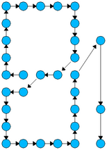
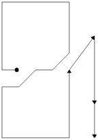