Got Beep

February 6th, 2006 by Keith Neufeld

Read the Manual, Stupid

Last week when I was trying to get the piezo buzzer to work with the LogoChip, I was in such a hurry to get to the sound that I skipped this part of the instructions:

Upon powering up, all of the user accessible pins on the LogoChip are configured as “inputs”. . . . Therefore, for the exercises in this document, we would like to always have all of the portb pins configured as outputs. . . . This can be done by creating the following special powerup procedure.

to powerup
write portb-ddr 0 ; turns all of portb into outputs
end

Last night when I soldered pins onto the piezo buzzer from the pager, plugged it into the LogoChip, and still couldn’t get sound out of it, I knew something was up. Finally it dawned on me that I didn’t know which way the ports were configured at boot, and looked at the getting started guide closely enough to find the section I quoted above. With the ports configured as outputs, it beeps just fine. Duh.

Beep Volume

I’m surprised at how quiet the beep is running on 5V, compared to how obnoxiously noisy the beep is in a pager on 1.5V. I changed back to the beeper from the microwave and it’s a little louder, but not much. Is the 1.5V in the pager really getting stepped up somehow? Tiny transformer, or voltage multiplier? Maybe I just need a driver transistor; I guess some experimentation is in order.

Beep Code

Making a beep was cute and simple, but booooring, so I made a little warbly sound.

to powerup
        write portb-ddr 0            ;   set port B to output at power-up
end

to startup
        warble 3                     ;   "warble" three times when the Go button is pressed
end

to click-on
        setbit 0 portb
end

to click-off
        clearbit 0 portb
end

to delay :n
        repeat :n [no-op]            ;   waste time by doing nothing, several times
end

to note :period :duration            ;   play a note of a given pitch for a given duration
        repeat :duration [           ;   repeat as long as requested
                click-on             ;   make a sound
                delay :period        ;   wait a little bit
                click-off            ;   make another sound
                delay :period        ;   wait another little bit
        ]
end

to warble :times        ;   make a warbly noise several times
        repeat :times [
                note 2 200           ;   make a low-pitched sound
                note 1 200           ;   make a higher-pitched sound
        ]
end

Of course, downloading a routine named powerup doesn’t automatically invoke that routine (unless you reboot the chip), so I invoked it manually from the console. Having done that, the routine makes a nice little warbly noise any time you type warble # at the console, or press the “Go” button on the circuit board.

Another thought: Since note‘s duration code loops around calls to the click-on, click-off routine, which calls delay to set pitch, the duration is actually impacted proportionally to the pitch of the note. It’d be interesting to rewrite the duration code to take input in ms (or seconds) and check timer to see when we’ve played the tone for long enough.

Pitches and Timing

If the code makes sense to you, then you’ll notice that I’m calling the delay routine with the second-shortest and shortest possible delays–twice and once through the loop. With delays of 2 and 1, the second pitch should be an octave higher than the first (twice the frequency)–but in practice, the one sound is only about a minor third higher than the other. That means that the overhead of calling the delay procedure is much higher than the delay of running once through a timing loop around a no-op.

Here’s the math: a minor third corresponds to a frequency difference of the fourth root of 2 (in equal-tempered tuning), whereas an octave is a factor of two. So if there were no overhead for calling the procedure, then the respective frequencies and periods would be simple doubles of each other:

f2 = 2f1
p1 = 2p2

But in practice

f2 = 4√2 f1
p1 = 4√2 p2

Let’s define tcall as the duration of the function call overhead (which should be constant) and tnoop as the duration of one trip through the loop in the delay procedure, including both loop overhead and the no-op operation (which we’re told is 13ms). (This ignores the fact that loop overhead will be slightly different when repeating and when exiting, but I suspect that the difference is small enough to be irrelevant. If anyone wants to check, I can measure frequencies for more delay values and give you equations in three variables . . .)

p1 = tcall + 2tnoop
p2 = tcall + 1tnoop

Then substituting back into the period relationship

p1 = 4√2 p2

tcall + 2tnoop = 4√2 (tcall + tnoop) = 4√2 tcall + 4√2 tnoop

2tnoop4√2 tnoop = 4√2 tcall – tcall

(2 – 4√2) tnoop = (4√2 – 1) tcall

tcall / tnoop = (2 – 4√2) / (4√2 – 1) ≅ 4.3

So if I did all that right (and I confess I ‘m pretty rusty), the overhead of calling delay is a little more than four times the delay of one trip through the no-op loop. Hmph.

Regardless of the relative values, the actual frequencies aren’t particularly high–higher than 440Hz, but well within the limits of my hearing. (I should test them tonight with my frequency counter.) That’s a bit disappointing for a 5Mhz-clocked chip running flat-out in a busy wait.

I thought about clocking the chip up to 40MHz per the instructions in the getting started guide (8x the clock speed = 3 octaves higher = outside the limits of my hearing), but I didn’t order the crystal and I didn’t have two 10Mhz crystals in my parts bin. Shucks.

I just talked to John, and he said that he and Tom McGuire were able to produce higher sounds using the chip’s built-in PWM. Not bad for a hack, but I wanted to use both channels of PWM for motor control. Think I need me a crystal.

Atmel/AVR Butterfly?

February 3rd, 2006 by Keith Neufeld

Whilst searching for the application note on using the native UART from the LogoChip (which doesn’t seem to exist), I ran across this discussion board about microcontroller programming from OS X.

What caught my eye was the mention of the Atmel/AVR Butterfly. John Harrison has been touting the Atmel micros to me, but mainly mentioning the GNU toolchain. The Butterfly is an evaluation board with an Atmel micro on it, a 100-segment LCD, mini-joystick, light and temperature sensors, speaker, RS-232 level converter, and headers to access all the ports.

But wait–there’s more! No separate device programmer necessary–it can download code through its RS-232 port! Now how much would you pay?

But wait–there’s more! All that comes on a board the size of . . . a table? Nope, smaller! A breadbox? Nope, smaller yet! A nametag! That’s right, folks; all that functionality on a board small enough to clip onto your shirt!

Now how much would you pay?!! $80? $130? Nope, less than that.

$20.

Twenty. Freakin’. Dollars.

Available from Digi-Key.

Starting up the LogoChip

February 2nd, 2006 by Keith Neufeld

Introduction to the LogoChip

A lot of the work in the Technology: Art and Sound by Design class will revolve around the LogoChip, a PIC18F2320 microcontroller (~$8 in 28-pin DIP) with scads of I/O pins and a Logo byte-code interpreter. (The Logo code is compiled on a host computer and downloaded to the chip.) The getting started guide gives examples to flash LEDs, beep piezo speakers, and move Lego motors.

The chip looks very promising for my own hobby use as well. I’ve been intending to dive into microcontrollers for a long time, and always assumed it’d be PICs. I have a BASIC Stamp (and a separate PIC) on my SumoBot, so that’d be one entry into microcontroller programming; but the LogoChip appears to be even easier to get into.

I’d been planning to follow up to my tilt sensor project with a PROM-based controller, but a little logic tells me that I’d need to quantize the sensor’s PWM output into at least 32 slices to get acceptable motor behavior, and that’s a lot of work to do in discrete logic. I’m afraid I’d overload my small motor just with the weight of the TTL DIPs required to do that. I had really wanted to build a motor controller without a microcontroller, just to show myself that it could be done, but I think it’s time to move on.

Building Circuits

The last two nights, I’ve breadboarded the LogoChip circuit, got it communicating with a host computer, and successfully built the cloning circuit to program the LogoChip code into the blank PICs I bought. The road to success was paved with annoying obstacles, though.

The getting started guide gives a schematic and step-by-step instructions to lay out the supporting circuitry on a breadboard. Of course, I’m stingy with space (I want as much room left over for other components to experiment with), so I managed to collapse the circuitry into the smallest possible amount of space. I saved .4″ over their design! Woo-hoo!

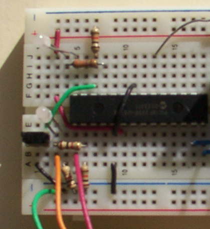
LogoChip on Breadboard

But I built and tested it using my bench power supply, forgetting that I was planning to power it with a 9V battery and 7805 voltage regulator. After I had it all working, I didn’t have room to add the 7805, so I had to stick it down at the other end, move the power switch, etc. ERROR.

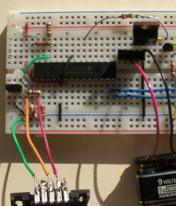
LogoChip and 7805 Voltage Regulator on Breadboard

Also, the guide’s schematic for the serial interface disagrees with its visual layout instructions, and the schematic is incorrect. The indicator LED and its current-limiting resistor need to attach directly to DB-9 pin 3 (the host’s TD / chip’s RD), not to the chip’s C5 (pin 15) as shown in the schematic. When attached to C5, it appears to pull down the signal too hard, and I couldn’t get serial communications to work.

[INSERT CORRECTED SERIAL INTERFACE SCHEMATIC HERE]

And, OBTW, the LogoChip goes into the circuit UPSIDE DOWN. That’s right, engineers–don’t try to insert it with pin 1 in the usual position, ’cause that’s not the orientation they chose to use. (???!!!)

I only did that once.

Mac Interface Troubles

The guide points to the files needed to install the LogoChip Desktop Software, but doesn’t give much information about what to do with them. I’ve written more detailed instructions on the class wiki. Strangely, the Java serial communications driver seems to require Classis (OS 9) support in order to install correctly–that’s the only difference I can find between my work desktop computer (where it installed and ran fine) and my notebook computer (where it didn’t). I still plan to get this working on my notebook somehow, so watch the wiki for updates.

Cloning LogoChips

The LogoChip has a cloning process to copy the Logo firmware onto another PIC. Because you can use this to get the firmware onto a chip without a PIC programmer (which I don’t have and haven’t built yet), I ordered blank chips from Digi-Key rather than preprogrammed LogoChips from Wellesley, and John loaned me one of his chips to clone.

The clone routine is a program that has to be downloaded to the LogoChip, not a permanent part of the firmware, so I couldn’t clone until I had the serial communications working. John loaned me the chip Tuesday and I promised to have it back today (Thursday), so that put some pressure on me to get the serial issues debugged. I ended up using my wife’s Windows machine last night for the programming.

Since I’m powering my circuit from a 9V battery instead of the 4xAA 6V pack recommended by the guide, I was curious whether I’d have to add another battery for clone circuit’s programming voltage, or whether I could get away with 9V. Googling for PIC18F2320 programming voltage led me to Microchip’s programming specification, which has an AC/DC Characteristics chart waaaay at the bottom which gives a range of 9.00-13.25V for high-voltage programming. Shiny!

I grabbed the unregulated 9V straight from the battery, threw another PIC on the board, hooked it up, and downloaded the cloner code into John’s chip. (Uh, John, did you realize I’d be overwriting whatever program you already had in there? Sorry about that . . .) Pressed the Go button, and– . . . uh, the button popped right out of the breadboard. I’m gonna have to solder longer leads onto that puppy. Jammed it back in long enough to hit it, and voila! Run light went green (“doing something”) and programming light came on.

[INSERT PHOTO OF CHIP CLONING WITH LIGHTS]

After a while (don’t know if it was four minutes like the guide said) the programming light went off and the run light went red (idle), and it was done. I pulled John’s chip out of the breadboard and put it in an anti-static bag to bring back, put my new LogoChip into the master slot, and cloned it onto another blank chip to make sure it worked. Same deal–lights came on, blah blah–and now I have two LogoChips. W00T!


Piezo Buzzer == NOT!

I tried hooking a piezo speaker to one of the pins to make a bleebledy-bloop program like the guide’s tutorial shows, but couldn’t get any sound. When I put 5V directly across it, it does click a little, so it may just need more current than the chip is supplying. I may try setting it up with a drive transistor to see if that helps; but I salvaged it out of a microwave, so I don’t actually even know for sure that it’s a speaker. Maybe it’s a secret Klingon nucrification death device.

I busted loose a piezo beeper from my stash of dead pagers, but it had SMT solder leads that I couldn’t just jam into the breadboard, so I let it go and called it a night.

And in Conclusion . . .

LogoChips are cool.

Welcome to Technology: Art and Sound by Design

February 2nd, 2006 by Keith Neufeld

This spring, I’m sitting in on a class called Technology: Art and Sound by Design, taught by John Harrison. The class interfaces engineering students with fine arts students, and microcontrollers with artistic expression. I’ve seen some of John’s cool toys, and I’m really looking forward to the things we’ll be building!

I’ve seen John for several years in his role as concertmaster of the Wichita Symphony Orchestra, so I confess to being a bit star-struck at actually talking to him and attending his class. It’s taking quite a twist of my brain to reconcile his stage presence (I’ve watched him play the solo violin in Vivaldi’s Four Seasons, for goodness sake) with his fun-loving, geeky side. Turns out he’s my age and has almost the same technology background I do–we both grew up with lots of the same microcomputers, programming assembler, writing games, etc. He diverged to music as a primary career, and I to computers.

I’m very grateful for his welcoming me into the class. He encourages my participation in discussions, in doing the projects, and in contributing to the class wiki. This should be a fun semester!

PWM Motor Control with a ROM

January 17th, 2006 by Keith Neufeld

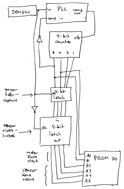
Here’s my next plan for motor control: Digitize the ADXL’s PWM signal into sixteen time sections (four left and four right) and use the resulting code and a PROM to generate a new PWM controlling the motor.

ADXL202 with PROM for Motor Control

More details to be added later.

Tilt Sensor and Motor Drivers, Take I and II

January 15th, 2006 by Keith Neufeld

After getting the PLL locked onto the signal from my ADXL202 tilt sensor and deriving separate left and right signals from it, I hooked it to the SN754410 H-bridge driver and wired up a motor salvaged from a toy car.

My goal is to control the motor’s direction using the H-bridge and its speed using pulse-width modulation (PWM)–the same signalling technique the sensor uses to indicate the magnitude of its tilt. I’d like the speed control to be proportional to the degree of tilt, so that a small tilt results in a slow correction from the motor, and a large tilt results in a faster correction.

With PWM speed control, the power to the motor is turning on and off at a fixed frequency, high enough to be irrelevant to the motor’s motion, but low enough not to cause problems with the induction of the motor’s windings. (Mine seems to be running at about 140Hz.) To make the motor go faster, leave the power on for a longer portion of each cycle before turning it off; to make it go slower, leave the power on for a shorter portion of each cycle.

In my first attempt, I wired the motor for locked antiphase driving. This control method constantly supplies power to the motor, but rapidly reverses its direction. To make the motor go faster forward, supply forward power for more of the time and reverse power for less of the time. This obviously consumes a tremendous amount of power, but also provides strong control over the motor’s behavior. It could be useful in getting a robot to stand still on a hillside, or hold its ground in a competitive setting without specifically trying to advance.

In my case, it just makes the motor vibrate. I suspect I’m not really supplying enough power to make it work, and the motor never does more than jerk a bit as I tilt the sensor toward its extremes. It was a nice idea–had it worked, it would have meant I could wire the sensor output directly into the motor driver’s input with no additional circuitry–but it just wasn’t meant to be.

For my second attempt, I used the left and right signals that I derive from the sensor and the phase-locked, 50% duty cycle signal, and wired them to the H-bridge inputs. Theoretically, this should have worked better than the locked antiphase control–with only one input active at a time, I should get more oomph out of the motor, and it might actually turn a bit instead of just jittering. Sadly, this still wasn’t the case. Apparently with this motor and only a 9V supply, 0-25% duty cycle isn’t enough to get it going, and certainly not enough go make it ramp up speed slowly with a slowly-increasing signal.

Those two methods were essentially freebies–all of the signals were available using parts I’d already wired onto the board. For my third attempt, I added a 74LS279 S-R latch, a logic device that remembers whether it has most recently been set (S) or reset (R) and holds its output accordingly.

I didn’t get very far in my experimentation before abandoning that line of pursuit as well. My thought was that I could use a master S-R latch to remember whether the motor was supposed to be turning forward or backward, and slave S-R latches to activate from the start of the duty cycle to the end of the “rightness,” or from the start of the “leftness” to the end of the duty cycle. This would change the effective duty cycle of the motor control from 0-25% to 0|50-75%.

The first complication was that my signal (sensor) and reference (PLL) don’t seem to be exactly in phase, or that the phase delay of negating one or the other is noticeable. When I view the derived left and right signals closely on my scope, I see a tiny spike at the start of each master duty cycle. Those spikes set and reset the forward-backward latch semi-randomly, preventing me from using this method without getting my phase timing more tightly calibrated than I want to have to rely on.

So just to test whether any part of the method was viable, I set up the left-tilted slave S-R latch to set (activate) as soon as the left signal is detected (remember, the earlier it is, the further left it’s tilted), and reset (deactivate) at the end of the master duty cycle. This gave a duty cycle of 50-75% for my S-R output, which I then fed into the H driver.

It was closer to what I wanted, at least; but not there yet. At 50% duty cycle, the motor is already running pretty fast for a small correction; and at 75% duty cycle, it’s perceptibly faster, but not as much so as I’d like. The real flaw is that even if this method worked, when it was nearly level, it’d oscillate between 50% forward and 50% backward. That’s a lot of action for a rig that’s already almost balanced.

I know, I know; the easy way to deal with this is to read the sensor with a PIC and set the motor behavior however I want in software. I’ll get there eventually. For now, though, I’m really hoping I can get this to work in discrete circuitry. Partly I’m interested in doing it for the experience (like building my own H-bridge board); partly I like thinking of this circuit as a low-level reflex, and doing it in software would make it feel more like a conscious action.

I’ll keep puzzling over more ways to do it in hardware–but I’m afraid it’s going to come down to inventing a linear pulse stretcher, which wasn’t on my calendar for January.

H-Bridge Motor Drivers

January 15th, 2006 by Keith Neufeld

If you want to reverse the direction of a DC motor, how would you do it? One of two ways:

  1. Change the positive voltage to a negative voltage
  2. Swap the two power leads

The first method is the simplest, but requires a dual-ended power supply–two sets of batteries, or a more complex circuit to split the voltage or generate the negative voltage from the existing positive. Either way adds overhead to the power supply.

The second method turns out to be the easiest to implement in practice, although it’s a bit tricky in an all-electronic solution. If you’re using relays to control the motor, you just use a DPDT relay with an off position, wired like so:

[insert relay schematic here]

To make the motor go forward, activate the FWD coil; to make it reverse, activate the REV coil.

The trick comes when implementing this in electronics. Most electronic switches (transistors) only pass electricity in one direction, so you can’t use a single switch to change the direction of current flow. The solution is an H-bridge, a set of four power transistors arranged like the upper and lower legs of an H, with the motor wired across the middle.

[insert H-bridge schematic here]

To make the motor turn forward, activate transistors 1 and 4. To make it reverse, activate 2 and 3. To burn out your transistors and power supply, activate 1 and 2 or 3 and 4.

On my CD-bot, I built an H-bridge from scratch out of (salvaged) small-signal, bipolar transistors. I wanted to do it from the ground up once, to know that I could. I also wanted to honor the goal that everything in the bot was made from salvaged materials, and I’ve never salvaged an H-bridge (as far as I know).

[insert picture of CD-bot motor driver board and 754410]

Since then, I’ve discovered the SN754410 quad half-H driver, which I purchased from Acroname. It’s a 16-pin DIP that provides four half-H-bridges, i.e. two complete bridges. It’s a piece of cake to use; and because one input controls an entire side of the H (transistors 1 and 2 or 3 and 4 in the diagram above), you can’t short it out with a simple mistake in the control logic. It’s a wonderful chip, I’m delighted to have found it, and I wonder why it’s not mentioned more often.

How to Make a 4046 PLL Work

January 13th, 2006 by Keith Neufeld

Success! I have the PLL locking onto the ADXL202 now, and my LEDs indicating tilt, all thanks to Lab 4: CMOS 4046 Phase-Locked Loop from a 1997 class at UC Boulder that I found via Google. Thank you, thank you, thank you for putting your courseware online (and leaving it there, apparently indefinitely)!

The lab explained two salient points that I hadn’t seen previously:

1MΩ ≥ [ R1, R2 ] ≥ 10kΩ
100nF ≥ C1 ≥ 100pF

and

How to test each subsection of the chip independently to building a working circuit from the ground up

So here are the values I ended up using. C1 = .1μF and R2 = 100KΩ gave fmin quite a bit slower than my sensor’s 80Hz output, but that was the closest I could do with what I had in my parts bin. Likewise, R1 = 68KΩ gave fmax quite a bit faster than 80Hz, but again, it’s what I was able to do with what I had on hand. I was able to test each of these frequencies and confirm correct operation individually by connecting VCO IN to ground (fmin) and to VDD (fmax) with no SIGNAL IN, and counting hash marks on my scope.

For the low-pass filter (R3 and C2), the cutoff frequency should be much smaller than twice the frequency of the incoming signal (sounds vaguely Nyquistish, eh?), in order for VCO IN to get the average DC component of the phase comparator output. I scratched and calculated a bit, but wasn’t really enjoying it, so picked values I knew would set the cutoff far lower than 160Hz–R3 = 1MΩ and C2 = .01μF. The price of my sin of laziness is that the circuit takes a few seconds to lock onto the input signal at powerup, but I can live with that for now. And because my input signal doesn’t have a strict 50% duty cycle, I’m using the Type II (edge-triggered) phase detector.

I also connected INHIBIT to ground. I don’t know whether it was strictly necessary, but another posting recommended doing so with unused CMOS inputs. It only cost me one more jumper to ground it, and as much trouble as I’d had already, I wasn’t going to let one more little thing stand in my way. Of course, I wired the tilt sensor’s output to the 4046′s input.

And everything worked at last! As noted above, the PLL takes a couple of seconds to lock to the input signal, but once it does, it’s rock-solid every time. It’s encouraging to see that once the capture range is set properly, the 4046 really works predictably. The scope shows the signal wiggling on power-up, but then it settles down.

I also got to use the external trigger input on my scope. I was wishing for a dual-trace scope so I could trigger off the sensor signal and compare it with the PLL signal on the same screen. Can’t do that on my single-trace, but I’m doing the next best thing–using the sensor signal as an external trigger to lock the PLL signal into position. True, I won’t be able to detect very small phase differences this way; but within the resolution of my scope, it sure looks as though they’re in phase.

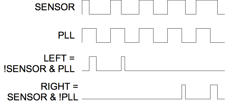
I wired up a 7406 and 7400 to give me the !SENSOR & PLL and !PLL & SENSOR combinations I described earlier, hooked them up to a couple of LEDs, and voila! Visible indication of the operation of my tilt sensor. A little more wiring, and I had four LEDs indicating bidirectional tilt. (Thank goodness the ADXL202 appears to use the same frequency generator for both axes’ PWM outputs, so I didn’t have to wire up another PLL for the Y axis.)

It works great! It works so well, in fact, that it demonstrates that I have the sensor positioned not quite level. And while I was fiddling with it trying to level it, I caused some intermittent connections on its contacts to its carrier. Oh well. It mostly works, and I know how to make it work, and I’m pretty happy about that.

POSTING IN PROGRESS

Solid-State Tilt Sensor with a PLL?

January 12th, 2006 by Keith Neufeld

In order to show off the ADXL202 tilt sensor, I want to hook up two LEDs that brighten and dim in response to the tilt. Because the sensor is +/- 2g, my PWM duty cycle is only varying from 25% to 75%, which isn’t enough to see the variation in brightness of my LEDs. Somehow, I have to translate that into a range that varies down to near 0%.

My ultimate plan for the tilt sensor involves controlling a motor (duh), and I expect to experiment with several different drive logic configurations. Regardless of how I end up driving the motor, though, it’d be nice to have indicator LEDs to demonstrate what decisions are being made and fed to the motor–so even if I don’t need any additional circuitry for the motor drive, I’d like to get the LEDs working.

I had previously considered, and am now looking carefully, at using a phase-locked loop (PLL) to help decode the PWM signal. A PLL locks onto the input frequency and provides an output signal of the same frequency–but with 50% duty cycle. A Type II PLL is edge-triggered, so it provides an in-phase output. (A Type I PLL’s output is nominally 90 degrees out of phase for a 50% duty cycle input.)

So if I can manage to get a PLL to work, I can use it to lock onto the fixed frequency of the tilt sensor’s output, and give me a reference signal that goes high at the same time as each pulse of the sensor, but goes low at exactly half of the signal period, while the sensor’s signal is going lower earlier or later depending on its tilt. Then instead of looking at the raw sensor data with a duty cycle range of 25% to 75%, I can compare the sensor to the reference and get “left” and “right” signals with duty cycles each varying from 0% to 25%.

ADXL202 and PLL

That means the LEDs would both be dark when the device is level, instead of each varying from dark to bright over the whole range–but I can live with that. It also means the LEDs will give a very direct representation of what I need the motor to do.

So I picked up a couple of 4046 PLL chips, and I’ve been reading the datasheets. Many, many times. After three or four readings, I understood that they were really going to do what I want with their Type II phase detectors. After another three or four readings, I think I have a pretty good idea how to select external components to set the frequency capture range I need. I don’t think I’m stupid–I’ve just never worked with these before.

I’m itching to try it out.

Solid-State Tilt Sensor, Unplugged

January 12th, 2006 by Keith Neufeld

Having got the ADXL202 working, I wanted to show it off, and then get it installed in a little project that I’ve had waiting in the wings. Showing it off has the side benefit of demonstrating the accuracy of my assumptions about how it works and how it interfaces, above and beyond being able to view its signal on my scope.

So this weekend, I breadboarded some LED drivers onto the sensor. I didn’t remember how much current the ADXL202 would source or sink; plus I wanted one LED to get brighter when it tilted left and another to get brighter when it tilted right. So I plucked a 7404 hex inverter out of my parts bin and wired one of the ADXL202′s outputs to a couple of inverters, then the output of one of them into a third inverter. This gave me two buffered outputs, one inverted and one non-inverted, which I wired through resistors into a couple of LEDs.

And because I wanted it to be portable so I could show it off, I left the benchtop power supply behind and strapped on a 9V battery and a 7805 voltage regulator. I cleverly soldered the black and red leads onto the wrong terminals on the battery connector, which I didn’t discover until I had covered the solder joints with nail polish (pink coral, if you’re curious) and cleverly smeared it around the breadboard when I accidentally touched the connector before it was dry.

Since the sensor’s PWM output is dramatically visible on the scope, I figured it’d be dramatically visible on the LEDs. Wrong-uh. Even knowing what was supposed to be happening, and with the LEDs’ domes carefully aligned in the same direction, in a dark room, I could just barely tell that one brightened and one dimmed as I rotated the assembly back and forth.

Feh.

Well, the ADXL202 is a +/- 2g sensor, and tilted vertically, it’s only experiencing 1g. That means my PWM duty cycle isn’t changing from 0% to 100%; it’s changing from 25% to 75%. I would still think that’d be enough to see a difference in brightness of my LEDs!, but apparently not. So I have to get smarter.