The Voron community comes across as antagonistic about a number of issues, one of which is: If your build surface is perfectly flat, there’s no need for bed mesh leveling!
Well, if your build surface is perfectly flat, good for you.
Even then, it would be more accurate to say that if your Voron 2.4 build surface is perfectly flat, the Voron is intrinsically incapable of using bed mesh leveling to improve it. (The Voron 2.4 levels the gantry to be parallel to the build surface by probing near the four corners. If the plane of the build surface isn’t square to the vertical members of the frame, the Voron has no way of determining that it’s always going to print non-rectangular parallelograms in the X-Z and/or Y-Z planes. But I digress.)
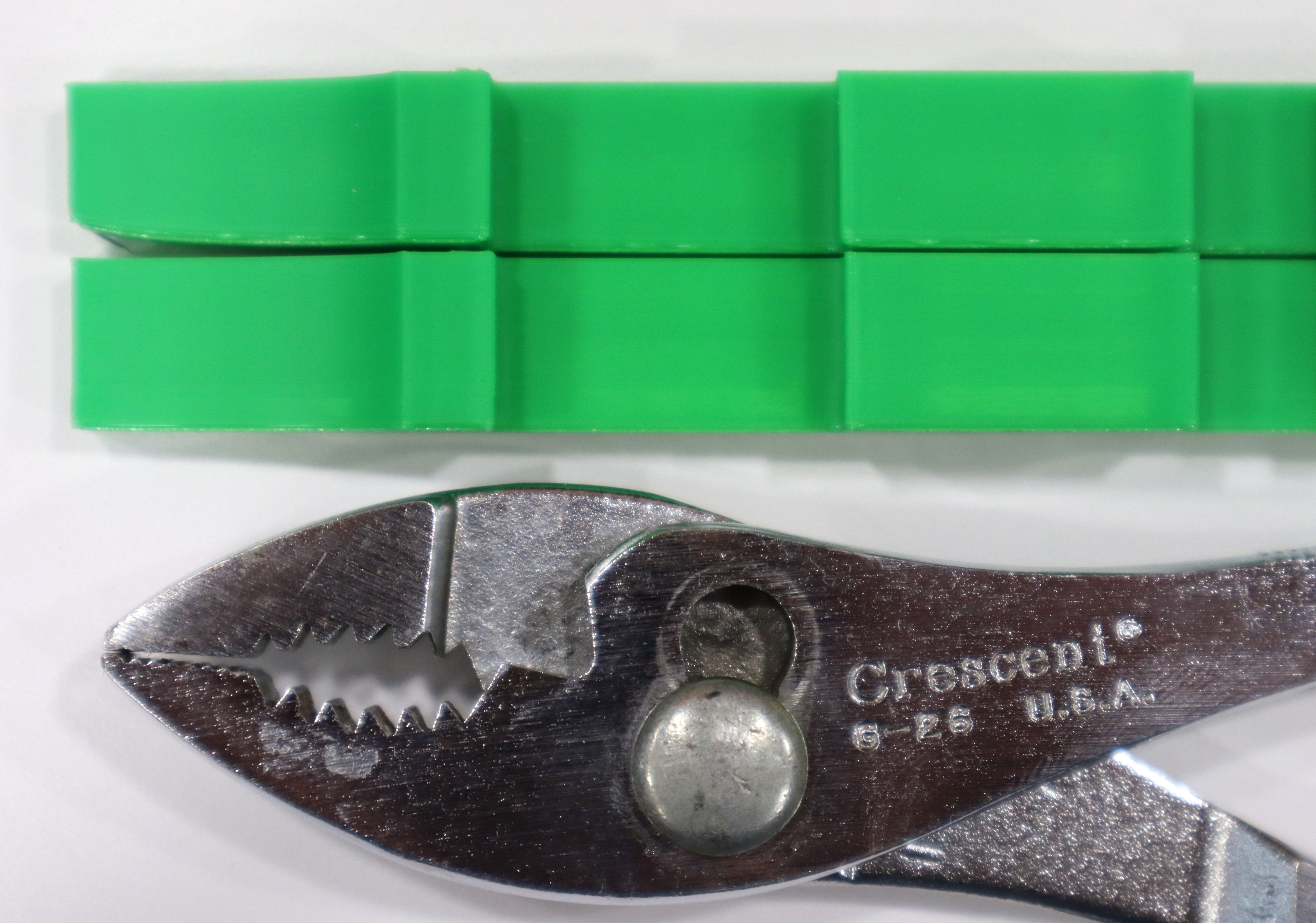
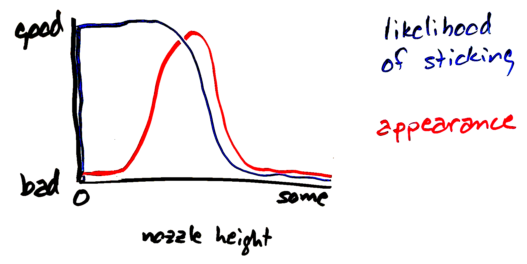
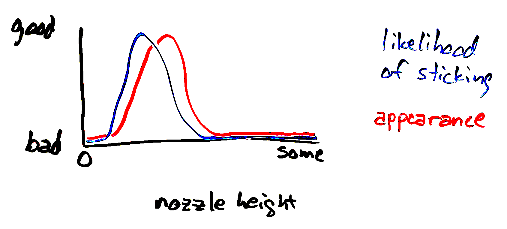
My aluminum heat spreader is not perfectly flat because it came in a kit from Fysetc rather than from a milling machine with a fly cutter; and my Voron 2.4 benefits tremendously from bed mesh leveling. (Above, without; below, with.)
To take my mesh to the next level, it’ll help to get the bed mesh configuration correct. The provided configuration is a useful starting point but can be improved significantly.
