Archive for the ‘CNC’ Category

Relocating the MakerBot CupCake Extruder Controller

Monday, March 8th, 2010

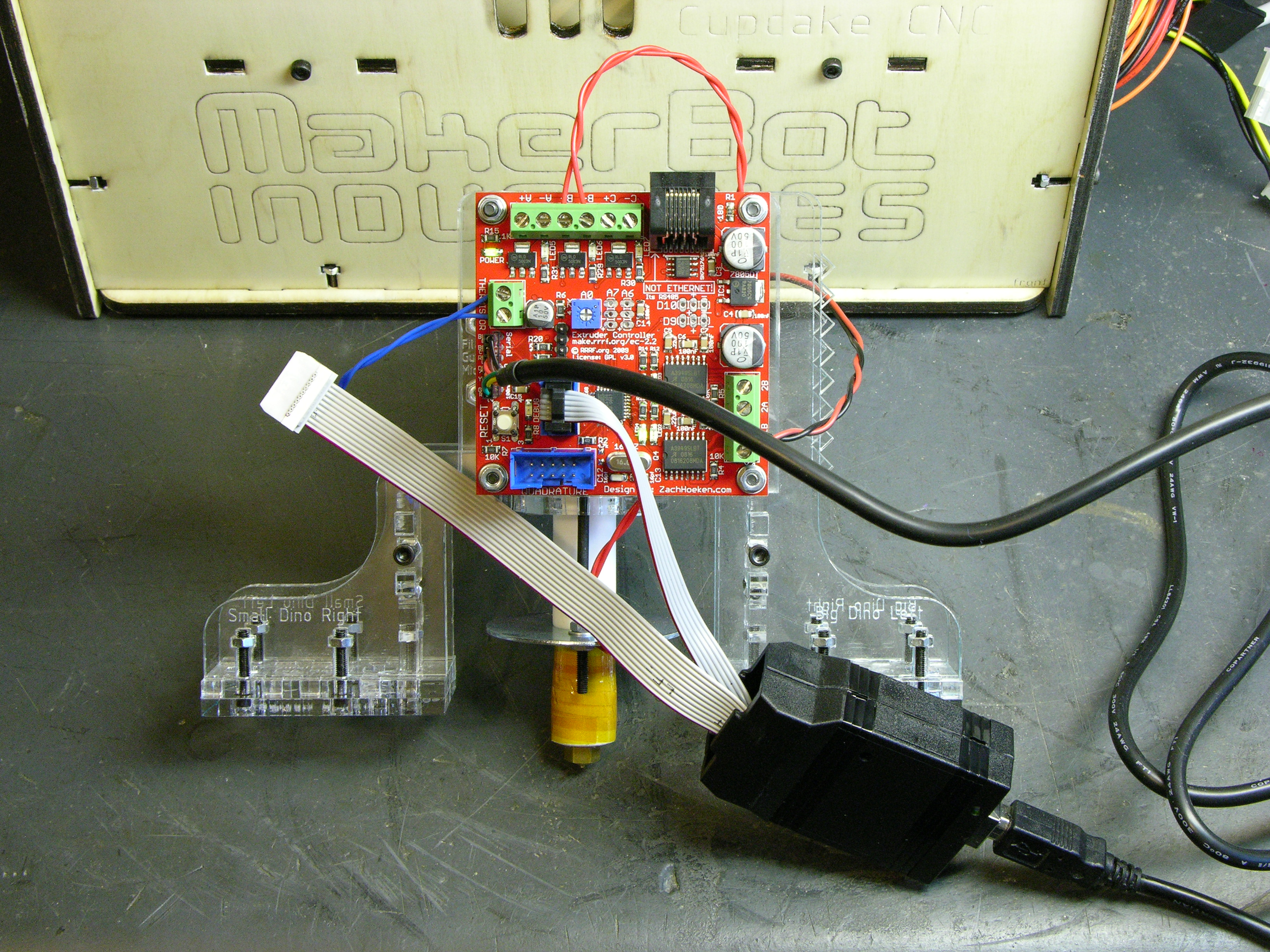
I’ve been dissatisfied with having the CupCake’s extruder controller attached to the front of the extruder. The PC board (being opaque) blocked the view of the feed mechanism. As much trouble as I have with filament feed, it’s pretty important for me to be able to keep an eye on it.

Actually, as many times as I’ve had to disassemble the feeder (replace broken idler pulley, reglue idler pulley, remove broken feed pulley flange, replace broken plastic?, etc.), I also got tired of having to remove the PCB every time.

And <whine>the patch cord didn’t route nicely from the side of the machine facing forward to the top of the machine facing up.</whine>

MakerBot CupCake with extruder controller moved to main body side panel

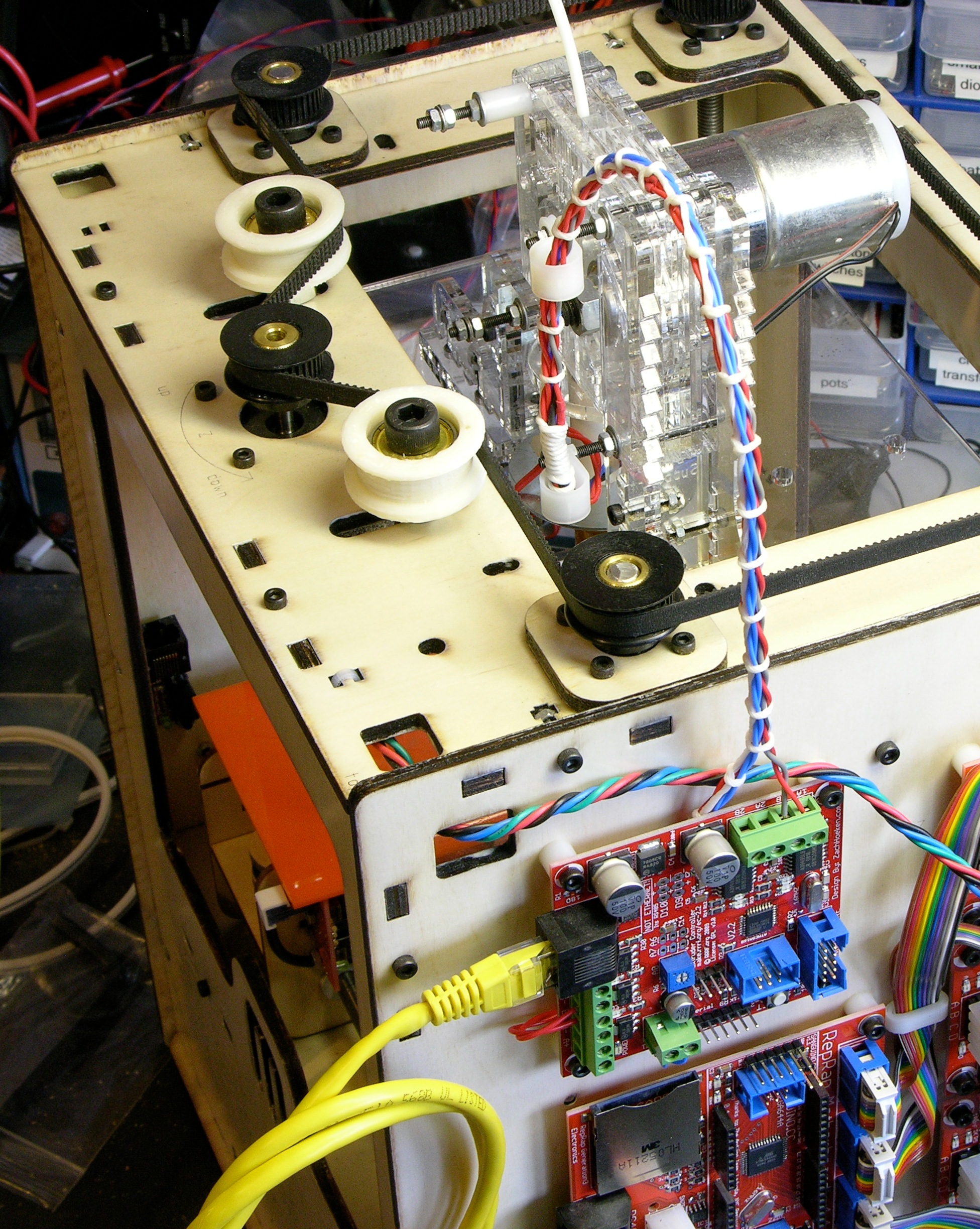
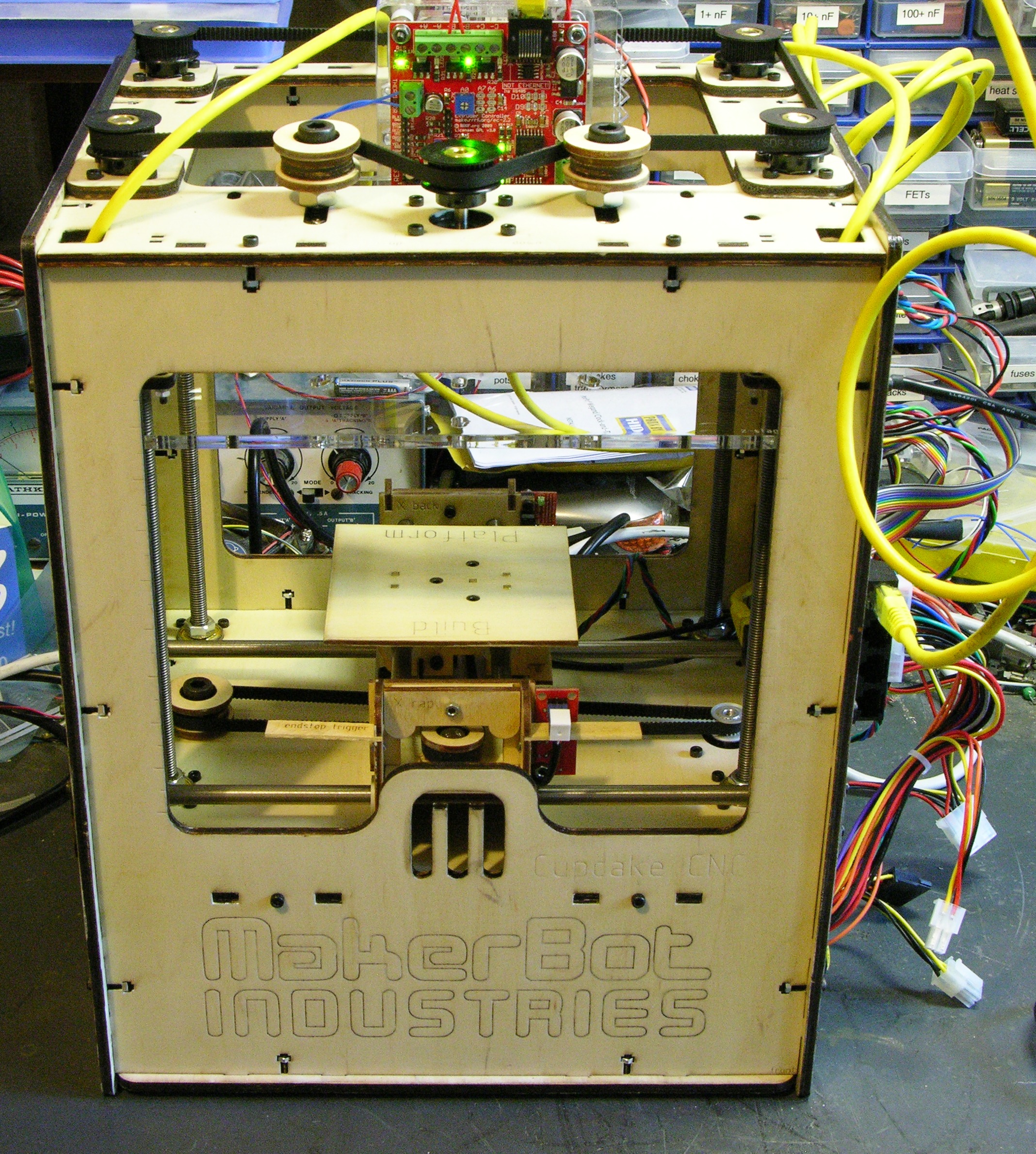
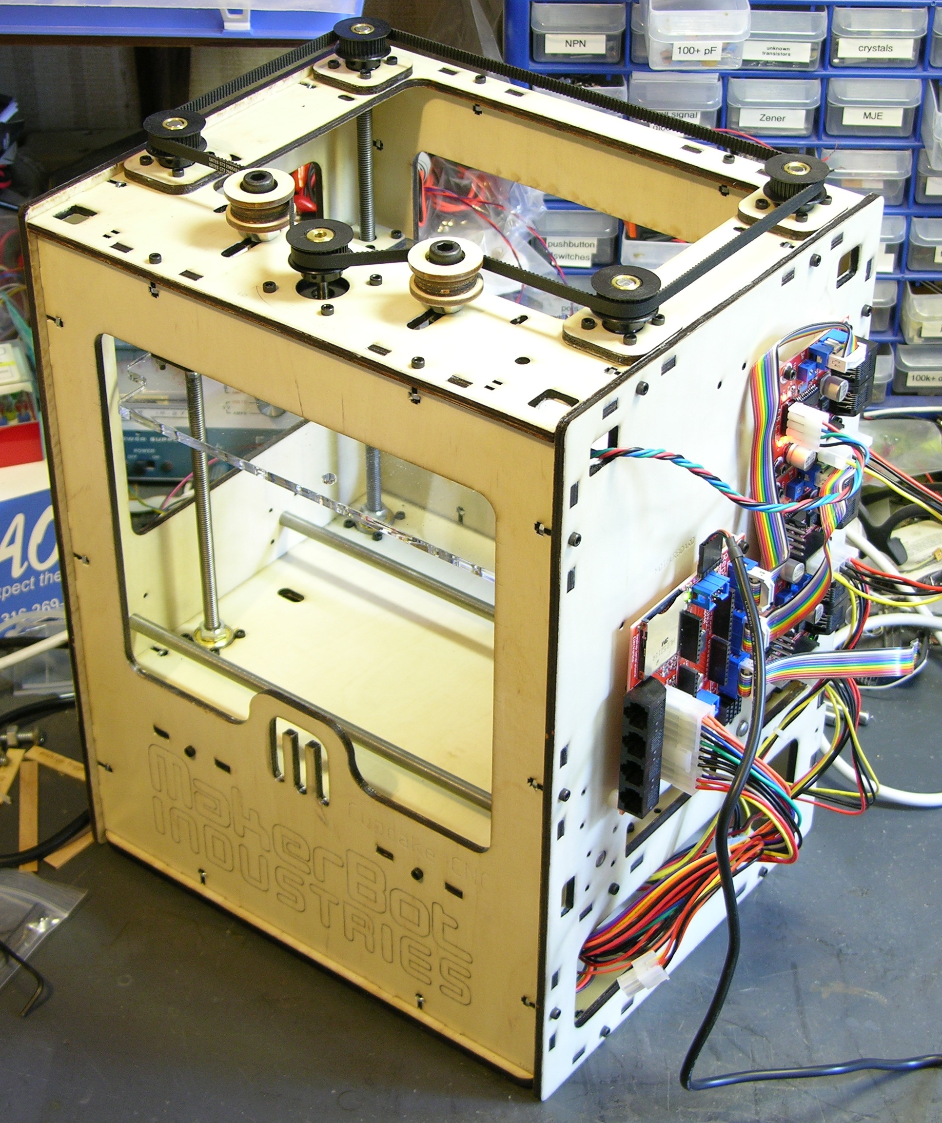
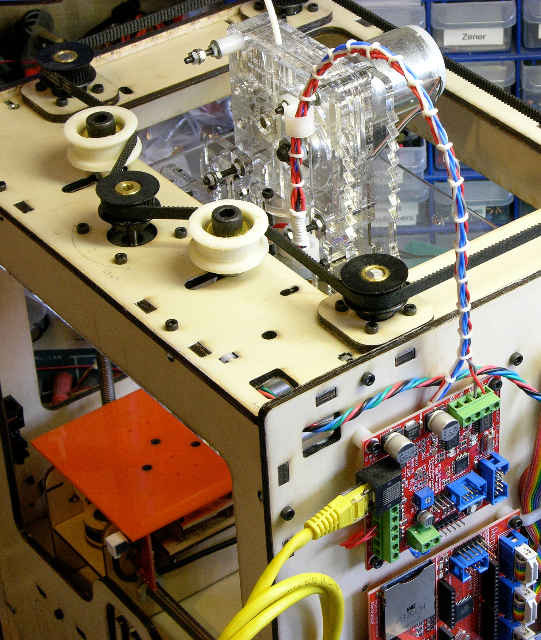
I’d previously mounted the extruder PCB up on the highest two screws of the extruder housing, placing it above the feeder face instead of covering it, but that was pretty fragile and I was constantly worrying about bumping it and snapping it off. This weekend I moved the extruder controller to its new permanent home on the right side of the CupCake in the empty space above the motherboard. It fits nicely and shares a mounting screw with the upper Z-axis endstop.

MakerBot CupCake with extruder controller moved to main body side panel

It does block access to the SD card slot, but I don’t use SD cards anyway. Even if I do someday, I think I’m most likely to put a card in it once and leave it there for doing prints without a host computer connected. Now that I’ve eliminated printing stalls and blobs, I don’t have a lot of reason to try uploading designs to a card every time before printing, nor save designs to a card from the host to then install into the machine.

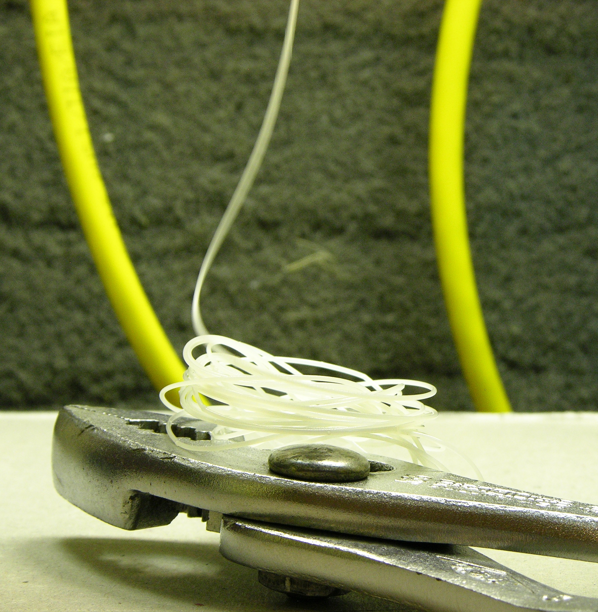
When I have time, I’ll make a shorter (4″?) patch cord to jumper from the motherboard to the extruder controller without all the excess I currently have coiled up.

Cable Lacing

MakerBot CupCake with extruder controller moved to main body side panel

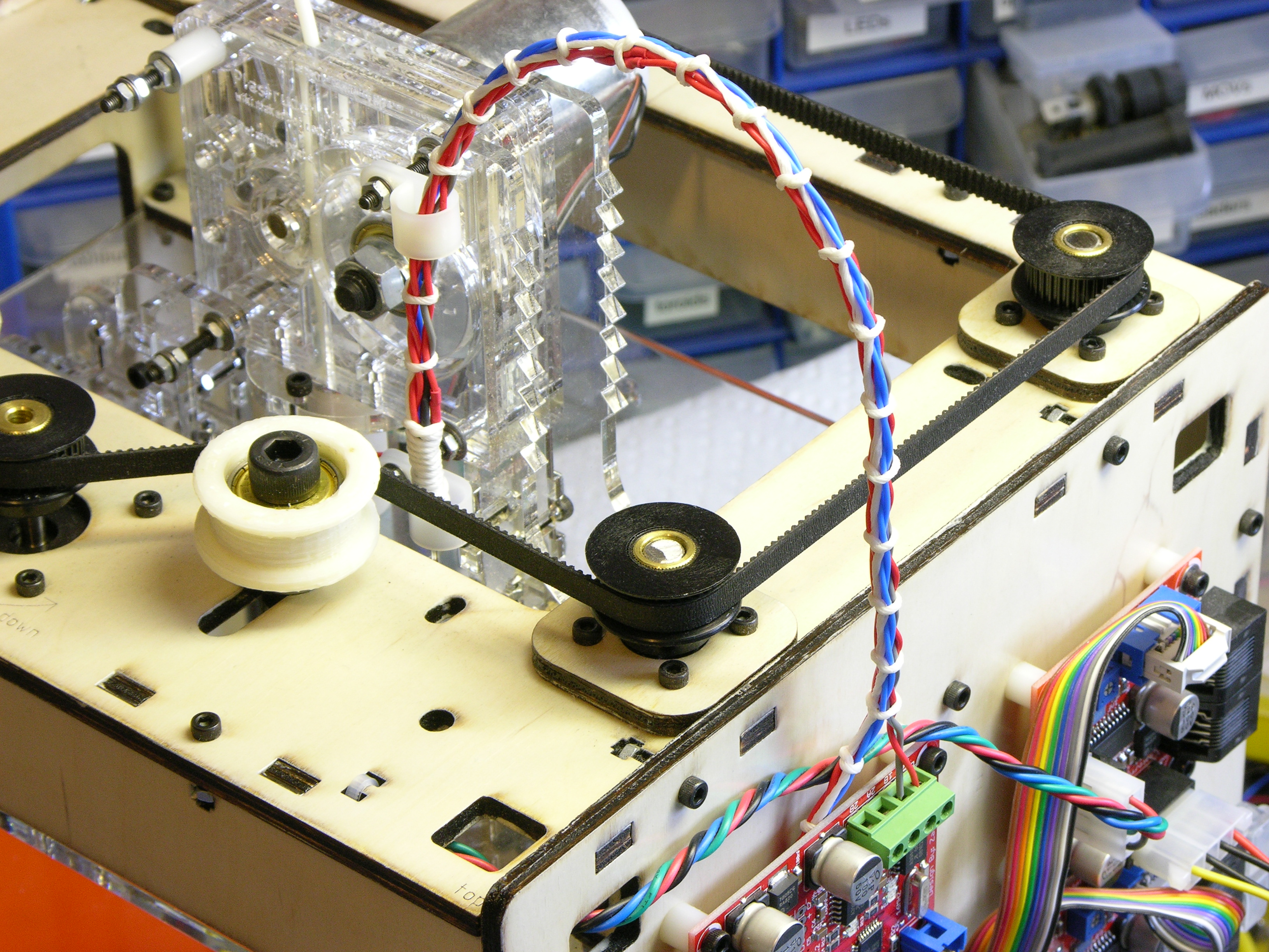
I also got to try my hand at cable lacing, something I’ve long admired in old TVs and vacuum tube organs. I don’t know that it’s the right look for a modern rapid prototyping machine, but the waxed string cost only a pittance and it doesn’t have to be the permanent solution.

The cable clips I had on hand were too big to anchor the mobile end to the extruder properly, but they do help guide the cable until I can buy smaller clips. Initially I had thought I’d need to enclose a piano wire in the cable bundle to help it maintain its arch, but it’s flexing very nicely without additional support.

Extruder Wire Gauge and Current

I’ve been concerned about the ability to deliver enough power to the extruder controller over the ethernet patch cord, especially when people are running heated build platforms off it too. I realized after the fact that I should have checked the wire gauge I was using before extending the heater wires out the top of the machine, but let’s check it now.

Powerstream.com provides a wire gauge and current table and calculator. For the 24-gauge wire I used, they list the maximum amps for chassis wiring as 3.5A, which is a comfortable margin over my actual current of 12V / 6Ω = 2A, so I’m safe.

Toward the bottom of the page they have a load calculator. Entering 24-gauge copper, 12VDC, 1.5′ one-way length, and 2A, they show a round trip .158V (1.32%) drop in the wire and 11.842V delivered to the nichrome heater. Not too bad.

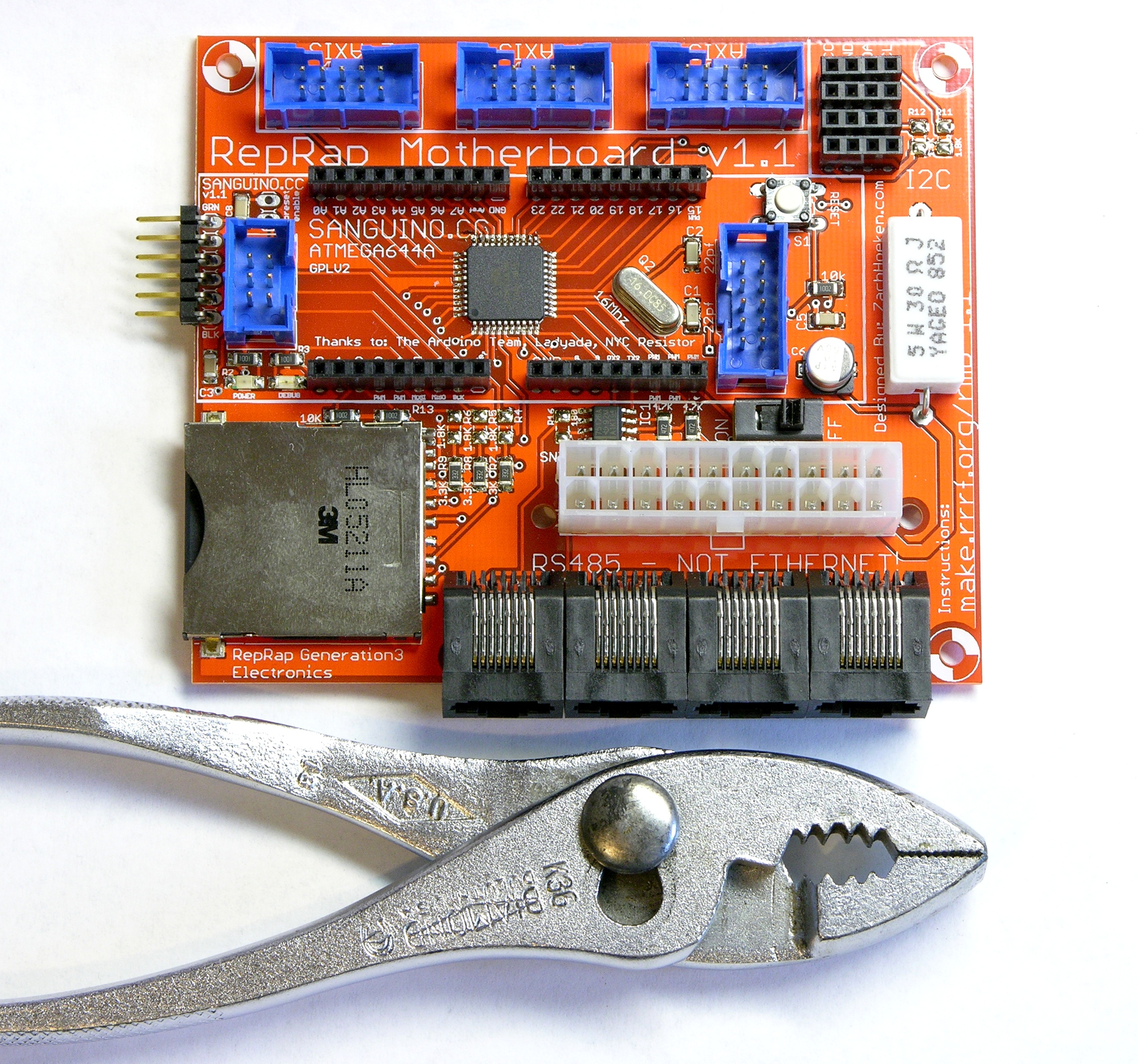
While we’re here anyway, let’s do the math for running both the nozzle and platform heaters from the extrusion controller in its original configuration. The interface uses three wires of the (almost certainly) 24-gauge patch cord for each of 12V and GND, so that’s equivalent to just over a single 20-gauge wire.

The nozzle heater was 2A and I see people talking about 4-6Ω platform resistance for another approximately 3A. The chart says 20 gauge is good for 11A for chassis wiring, which is a comfortable margin. The calculator shows a .314V drop over the 3′ patch cord, still delivering 11.7V to the extruder controller. Quite acceptable and nowhere near as bad as I feared.

Fixing CupCake Build Problems

Thursday, December 24th, 2009

In the last couple of months, I’ve worked through and fixed several major problems with my CupCake hardware and Skeinforge slicer settings that were preventing me from printing any useful models: warped build bed, infill density, printing stalls causing blobs, XY slowdown on curves causing blobs, and bizarrely bad printing.

Making a Less Warpable Build Bed

I switched a while back from the included foamcore build surfaces to a scrap of plexiglas, to which the extruded ABS sticks more securely and from which it releases after the build without damage. Initially I taped the plexi to the build platform at the corners; but as the the model being printed cooled and began to shrink, the plexi warped upward with it and the tape was insufficient to keep the plexi (and model) flat. The warped upper surface of the build then snagged the nozzle, the steppers lost steps, the next layer(s) got out of alignment, and builds were ruined.

MakerBot CupCake build platform with plexiglas build surface

(more…)

Calibrating the CupCake Part 1: Nozzle Temperature

Friday, September 11th, 2009

Measuring width of Spam can at grocery store

Last Saturday I went shopping for lunch with a tape measure.

Frying Spam for lunch

Delicious Spam™, fried up nice and crisp and served with Grannie’s “homemade” [what exactly does that word mean?] mustard. Yummmm!

The behavior of my CupCake during the first week of testing and parts-building had made me think that the nozzle was actually colder than the extruder controller believed it was — barely able to push plastic at allegedly 220°C and much happier at 230°C with not much scorching.

MakerBot CupCake plastruder with nozzle in water

I had previously cross-referenced the extruder’s reported temperature with my infrared thermometer’s reading at room temperature (which I no longer trust) and had dipped the heated nozzle into a small pool of water to try to find the boiling point.

Condition Thermometer Measured Thermometer Converted Thermistor Reported
room temperature 68°F 20°C 16°C
dipping nozzle into water and adjusting set temperature until water boils 105°C

In the 100-115°C range, the water would sizzle when the nozzle heater was on and stop boiling when it was off. It boiled most evenly between heating and cooling at a reported 105°C, so I was guessing that it thought 100°C was really 105°C.

This turned out to be incorrect; but it convinced me to perform a more proper thermal calibration, which is what counts.

(more…)

CupCake First Prints

Thursday, September 3rd, 2009

This post is for anyone thinking about a CupCake and wondering what the extrusion is really like. The rest of y’all, go away for a bit.

MakerBot CupCake test extrusion

First extrusion, no CAM happening, just heating up the extruder and running filament.

(more…)

Programming the CupCake Motherboard and Extruder

Wednesday, September 2nd, 2009

Because the (early batch) CupCake circuit boards are assembled by the customer (me), they’re unprogrammed and the customer (me) has to use an in-system programmer (ISP) to burn the bootloader and then an FTDI USB-serial cable and Arduino development environment to program the firmware. Happily, the prerelease kit included both a USBtinyISP and the necessary FTDI cable, so I was good to go.

I got the bootloader programmed into the motherboard just fine, but I couldn’t get the Arduino IDE to program the firmware into it (and yes, I did install the Sanguino support). The motherboard has a switch to signal the (PC ATX) power supply to turn on and feed all the peripherals; but it’s emphasized that standby power is always provided to the ATmega on the motherboard, so there were no steps needed to power up the ATmega for firmware download. Further, the motherboard power switch didn’t power up the power supply, so I figured it must not be needed yet.

But every time I tried to upload firmware, I kept getting a long timeout and:

Binary sketch size: 15002 bytes (of a 63488 byte maximum)

avrdude: stk500_recv(): programmer is not responding

as though the Arduinoness of the motherboard wasn’t there.

Lots of MakerBot forum posts identify the same problem and talk about jumpering the power supply cable to make it turn on.

C’mon, that can’t be for real. The programming instructions don’t say anything about needing to mess with your power supply cable, and that would be a massive omission.

Maybe another look at the motherboard power switch? Switching it didn’t make anything happen, and the schematic for my V1.1 motherboard shows that the power-on signal to the ATX power supply is under the control of Arduino digital pin 14 — a chicken and egg problem.

MakerBot CupCake motherboard with power supply jumpered for initial programming

After about an hour of searching CupCake and RepRap forums, poring over the schematic for anything I might have missed, trying different random things, and generally getting pretty good and angry, I gave up and used Wikipedia’s ATX power supply entry to help me jumper the power supply’s power-on lead. The power supply came on and the motherboard programmed on the first try.

You’re kidding me. This is a necessary step, it causes so much trouble that everybody posts about it in the forums, and it’s still not covered in the assembly instructions? I honestly still think I must be missing something.

Programming the MakerBot CupCake plastruder controller

Fool me twice, shame on me. When it was time to load firmware on the extruder controller, I found that leaving the USBtinyISP connected from the computer to the PC board’s ISP header is a great way to supply the microcontroller with power for the first Arduino firmware upload.

Yes, by this point the motherboard was correctly controlling the power supply; but this was a handy trick I need to remember.

CupCake Pilot Assembly

Wednesday, September 2nd, 2009

MakerBot CupCake, all motors installed

As of a weekend ago, we are assembled! There are changes to be made, but they’ll clean up along the way.

Notes from the process:

All of the cables will get proper cable management. I won’t show closer pictures of them until they do.

(more…)

Mouse Cables for CupCake Endstops

Tuesday, September 1st, 2009

I finished assembling my CupCake a week and a half ago — more detail in a separate post. For now, information about my decision to use mouse cables to wire up the endstops.

The CupCake comes with CAT5E (ethernet, among other things) patch cords to use to connect everything together. The X stage doesn’t have room for 8P8C (RJ-45) connectors on the Y-axis endstops, so you have to butcher the cables and put one new end on each. Ethernet patch cords are pretty bulky and unsupple; and I figured since I had to terminate my own cables anyway, I might as well use something more to my liking. I don’t fault MakerBot for supplying patch cords — it’s a great choice for most makers, and weirdos like me can always roll their own.

I only needed three conductors and headphone cable is pretty supple; but the very fine stranded wires inside headphone cable can be a bit of a challenge to work with. Cords from dead mice seemed like a better fit, even though they have an extra conductor I didn’t need. So I grabbed some from the “Keith box” at the office and got to work.

Mouse Guts

Interior of optical mouse

For those who haven’t seen it before, here’s the inside of an optical mouse.

(more…)

Assembling the CupCake

Monday, August 17th, 2009

After leaving the case parts outside in the van for a week to cure, by Saturday they were nice and dry and didn’t feel squooshy when I was putting together tight-fitting pieces. Saturday evening I got the case assembled and the Z stage installed:

MakerBot CupCake with Z stage and some electronics installed

And more yesterday afternoon and evening.

(more…)

Finishing CupCake Case

Sunday, August 9th, 2009

I received my CupCake kit around the end of April; it’s now August and I haven’t completed it yet. What’s up with that??? Well, I’ve been finishing the case.

That’s a pun. Here, let me spell it out: I’ve been completing the case by applying wood finish to it.

White “Stain”

I decided early on that I wanted the case to be as light-colored as possible so the interior would illuminate well to watch and photograph builds; but that I wanted to honor the fact that it’s made of plywood and let the wood grain show through.

Back side of plywood from MakerBot CupCake case

That said, the back sides of some of the plywood pieces are a bit rough. (The fronts are all very nice, and both sides of the 1/8″ pieces are nice.) Although the rough sides all face the interior, the interior is where I’m going to be looking and photographing a lot. So a lightening agent with a bit of opacity –but not too much — seemed like a good idea.

Vicki the Paint Lady at Graber’s Ace Hardware led me to a Zar “country white” oil-based wood stain that she had used before and which very closely resembles an oil-based paint. It applies like a stain, but the color particles are white and more opaque than I’m used to from regular wood stain. I had to be a bit careful in the application not to leave it on so thick as to completely hide the wood grain; but I was pleased with the result.

Unfinished plywood against plywood with one coat of white stain

The smaller, upper piece is untreated; the lower background piece has one coat.

(more…)

(Mostly) Assembling My CupCake Motherboard

Monday, May 25th, 2009

The MakerBot CupCake‘s motherboard (RepRap generation 3 motherboard) is Arduino-compatible, connects to all the other boards in the CupCake / RepRap, and has lots of spare connectors to boot.

Ah, spare connectors to prototype, I mean; the spare connectors aren’t needed in order to get the board to boot. Ha ha.

Mostly-assembled CupCake motherboard

I got mine mostly assembled last week. Like every other piece of electronics in my CupCake kit, my motherboard had missing parts — I got five extra 4.7KΩ resistors instead of the five 1.8KΩ resistors. And unfortunately, that was another part for which I couldn’t find replacements at hand — although I did end up sorting and filing a bunch more SMT components while searching.

After waiting a week for the missing resistors as the solder paste was drying out and getting crusty, I gave up and baked the thing without them. I can hand-solder the 1.8KΩ resistors onto the board when they arrive. And because they’re voltage dividers for 5V → 3.3V level conversion to the mini-SD card and pull-ups for the I2C bus — neither of which is needed for basic operation — I can even run the darn thing without them. I just need to get them on there eventually.

Crusty solder paste bakes just as nicely as gooey solder paste, by the way.

Unlabelled R1 on MakerBot Cupcake motherboard

I did spend a while searching for the placement of R1 on the PC board. I eventually found it through a combination of the process of elimination and checking the schematic. As far as I can tell, the name label didn’t make it anywhere onto the silkscreen — can you spot it?