Archive for the ‘MakerBot CupCake’ Category

MakerBot CupCake Aluminum Idler Wheel and Printing in Plaid Due to Motor Shaft Deflection

Tuesday, May 25th, 2010

Aluminum idler wheels for MakerBot CupCake

At the end of March, I broke my MakerBot CupCake idler wheel while trying out my new filament drive worm-pulley. In April, my friends Scott Smith and Ben Wynne in San Diego machined me some aluminum replacement wheels, which are totally awesome.

Broken acrylic and replacement aluminum MakerBot CupCake Plastruder idler wheels

Old and busted; new hotness. Yeah, baby!

This wheel press-fits perfectly onto the bearing, starting by hand and then leaning heavily on it on a countertop. It’s thicker than the original wheel, making precise alignment with the drive pulley less important. It even has a knurled edge — showoffs!

Plaid print from MakerBot CupCake

I’d been experiencing “plaid” printing, in which the filament feed rate dropped at very regular intervals, and attributed it to the (tangible) irregularities of the acrylic idler wheel. But I’m still getting plaid prints, and I don’t think my aluminum wheel (hot off the lathe) is irregular, so the problem must be elsewhere.

MakerBot CupCake filament feed

Hm, look at the deflection of my filament feed motor shaft, all the way to the left of the hole in the enclosure.

MakerBot CupCake filament feed

Hm, look at the deflection of the shaft now, when the flat hits the edge. That would explain why the weak feed is so regular — recovery doesn’t rely on the drive pulley maybe grabbing the filament and maybe being able to spin the idler wheel to a different spot before it gets going again.

Looks like I need a bearing on that motor shaft. I printed a shoulder washer/bushing for it and it helped for a while, but not enough. I think a real, metal bearing is in my future. And perhaps a different drive geometry. A lot of good filament feed designs are being uploaded to Thingiverse.

Glastherm HT Insulation with Glass Standoffs for Hotplates

Monday, May 3rd, 2010

As I discovered a couple of weeks ago, Glastherm HT is not a good enough insulator to protect the acrylic mounting plate under my MakerBot CupCake heated build platform. Last night I tried it with glass standoffs between the hotplate and the Glastherm.

Glass feet taped to underside of MakerBot CupCake heated build platform

I had some leftover glass from having a window cut recently. I bought a glass cutter and cut a half-inch strip off the end of one of the pieces, then cut that into smaller tiles. I smoothed the sharp edges on a diamond file, then pried apart the hotplate sandwich and stuck the glass tiles onto the leftover kapton tape.

Checking insulating value of Glastherm plate on glass standoffs under MakerBot CupCake heated build platform

I repeated my earlier test, standing the sandwich on edge on another piece of insulating material and running the heated build platform up to (and past) operating temperature. (Sorry no laser dot in the picture — I’m not quite coordinated enough to hold the thermometer’s capture button, point it the right direction, hold my hand still, and take a picture all at the same time.)

Plate Temp Back Max Temp Back Min Temp
120°F 85°F
145°F 95°F
175°F 120°F 105°F
Approximate CupCake target temperature
220°F 155°F 135°F
310°F 200°F

The air gap did a considerably better job of insulating than the Glastherm alone. Also when I remembered to measure the temperature separately under the glass feet, the spots were 15-20°F hotter than the rest of the Glastherm, suggesting that smaller glass dots could provide a significant further reduction in heat transfer.

Testing Glastherm insulation on glass standoffs under MakerBot CupCake heated build platform

135°F on the back side is pretty manageable; 200°F is a bit warm to be in contact with plastic. However, as Leon pointed out last time, it’s not just about how hot the back side gets, but about how rapidly the heat is transferred into the backing material.

I set the heated platform onto a spare piece of plexiglass and also dropped some scrap filament onto the top of the platform. Already above operating temperatures, the filament softened nicely and the plexiglass stayed cool to the touch and didn’t warp. Leaving the setup unattended for a while and letting the platform drift up to 340°F, the plexi got a little soft.

I think this is usable for the CupCake, but I’ll need to exercise a little care managing the plate temperature (and I’m overdue hooking up the thermistor for closed-loop temperature control). I think this may not yet be enough insulation to tape my SMT hotplate directly on top of a plastic enclosure and run 290°C (~550°F) soldering temperatures.

Glastherm HT: Not So Good for Insulating Hotplates

Monday, April 19th, 2010

Two pieces of Glastherm HT for aluminum hotplates

I got a care package this week from my friend Scott in San Diego. Half of it was two pieces of Glastherm HT that he cut to fit my soldering hotplate and my MakerBot CupCake heated build platform. Scott and his buddy Ben Wynne are building hotplates and were also planning to use Glastherm to insulate them.

Last night I pried the warped acrylic off the underside of my platform, cleaned the surfaces with alcohol to ensure a good stick, and affixed the Glastherm to the heater PCB with kapton tape. I then set the assembly on edge on another piece of Glastherm and ran it up to operating temperature.

Testing Glastherm HT insulation on MakerBot CupCake heated build platform

The Glastherm was not nearly as good an insulator as I expected. The “cold” side of the sandwich lagged only 25°F behind the hot side as I was heating it from room temperature and once it stabilized at 250°F, (at which point the “cold” side reach equilibrium around 225°F).

I’m surprised that the Glastherm provided so little insulation. Perhaps it’s not intended to be used in direct thermally-conductive contact with a hot surface — although the diagram on their web site certainly suggests that it is.

At any rate, the “cold” side of my sandwich is still far too hot to be in contact with my acrylic mounting plate. And since Glastherm is supposed to be pretty good stuff, I think I’m resigned to finding a way to assemble my sandwich that leaves an air gap between the heater and the mounting plate, which I hadn’t wanted to do.

Threaded Pulley for MakerBot CupCake Extruder

Monday, March 29th, 2010

All along, I’ve been having trouble with the filament feed on my CupCake extruder. Regardless of how closely I position the idler wheel to the drive pulley, the slightest blockage at the extrusion nozzle (even sometimes removing the text extrusion with needlenose if I get too close) causes the timing pulley to ream out a pulley-sized divot from the soft ABS.

There’s then no way for the extruder to move the filament — forward or backward — until I get pliers and apply considerable force to the filament at the intake to move the divot past the pulley.

Brass pulley with threaded groove

In April last year, nophead tested different drive methods and found the threaded pulley (as above) to provide the strongest grip on ABS. (Search in page for “The final test was a threaded pulley” to see his technique and results.)

nophead isn’t the first to use this technique to manufacture a threaded pulley and I’m not the first to copy his notion of using it on a RepRap, but I’ve lost my links to many of those who have done it before.

At any rate, I installed one on my CupCake this weekend and the results are considerably beyond my expectations. Here’s the story.

(more…)

MakerBot CupCake Heated Extrusion Bed Part 4: Putting It All Together

Saturday, March 20th, 2010

Thanks to nophead’s discovery that kapton tape makes a perfect ABS extrusion build surface, I knew that I wanted to cover my heated MakerBot CupCake build platform with it. While Scott was milling me a plate, I ordered a roll of 4″ kapton tape and a roll of 1″ double-stick kapton tape from eBay seller mn-vac, whom I can’t recommend highly enough. He had some long-running auctions that he had updated to indicate that he was out of town and wouldn’t be able to ship for a couple of weeks, but still responded immediately to my questions and had the package shipped to me well before he was even scheduled to return.

Acrylic base and aluminum plate for MakerBot CupCake heated build platform

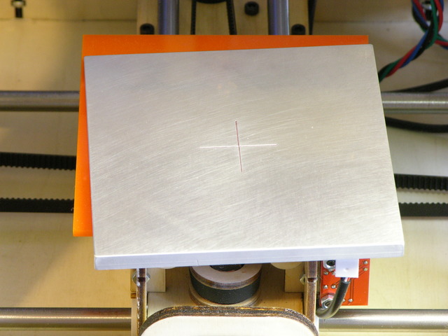
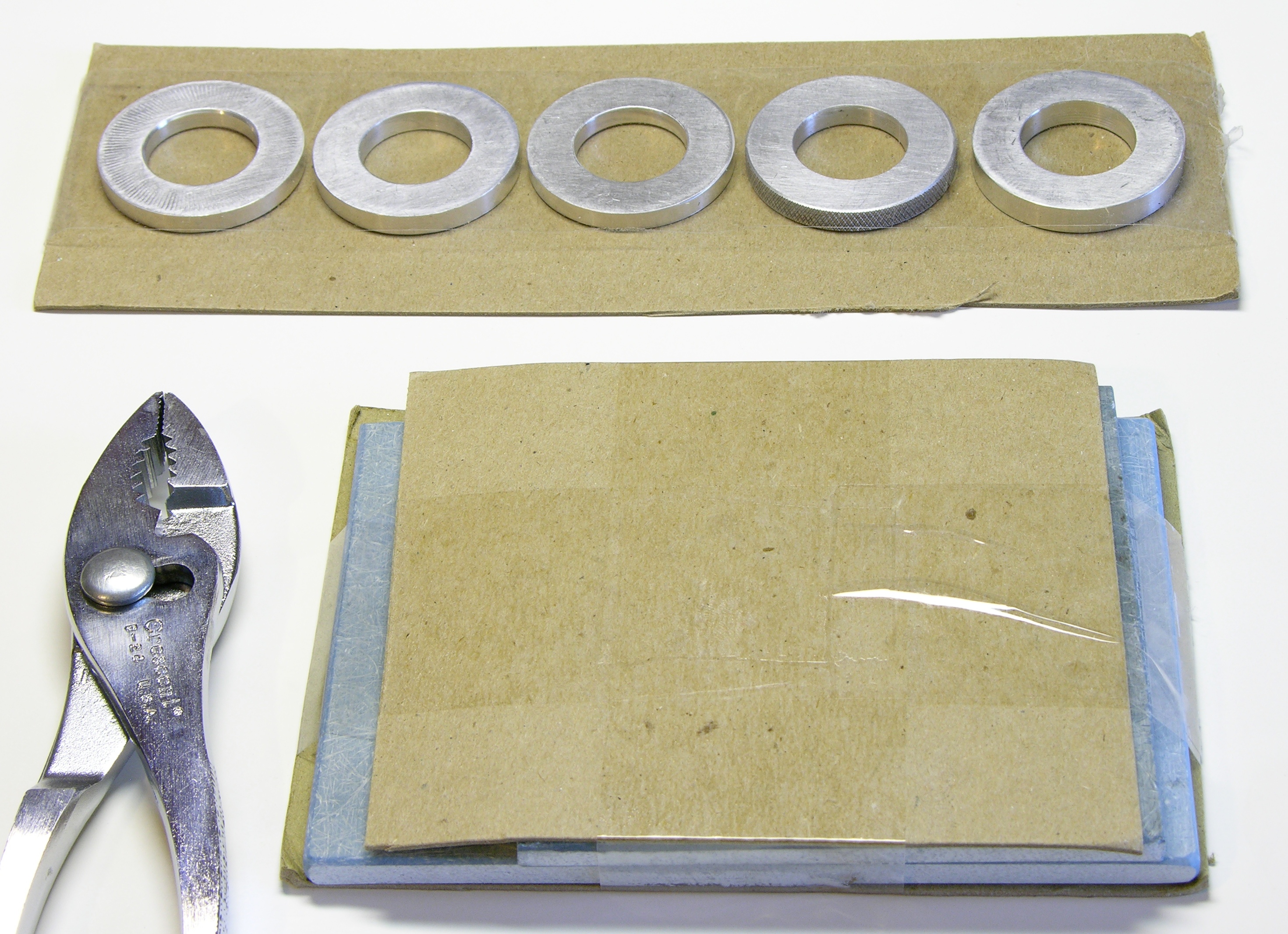
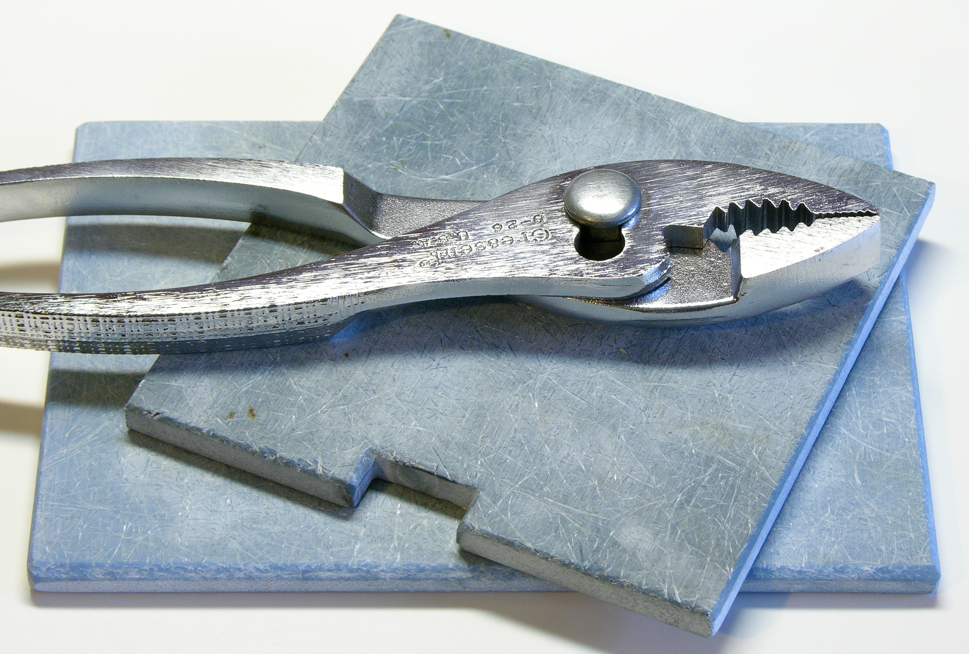
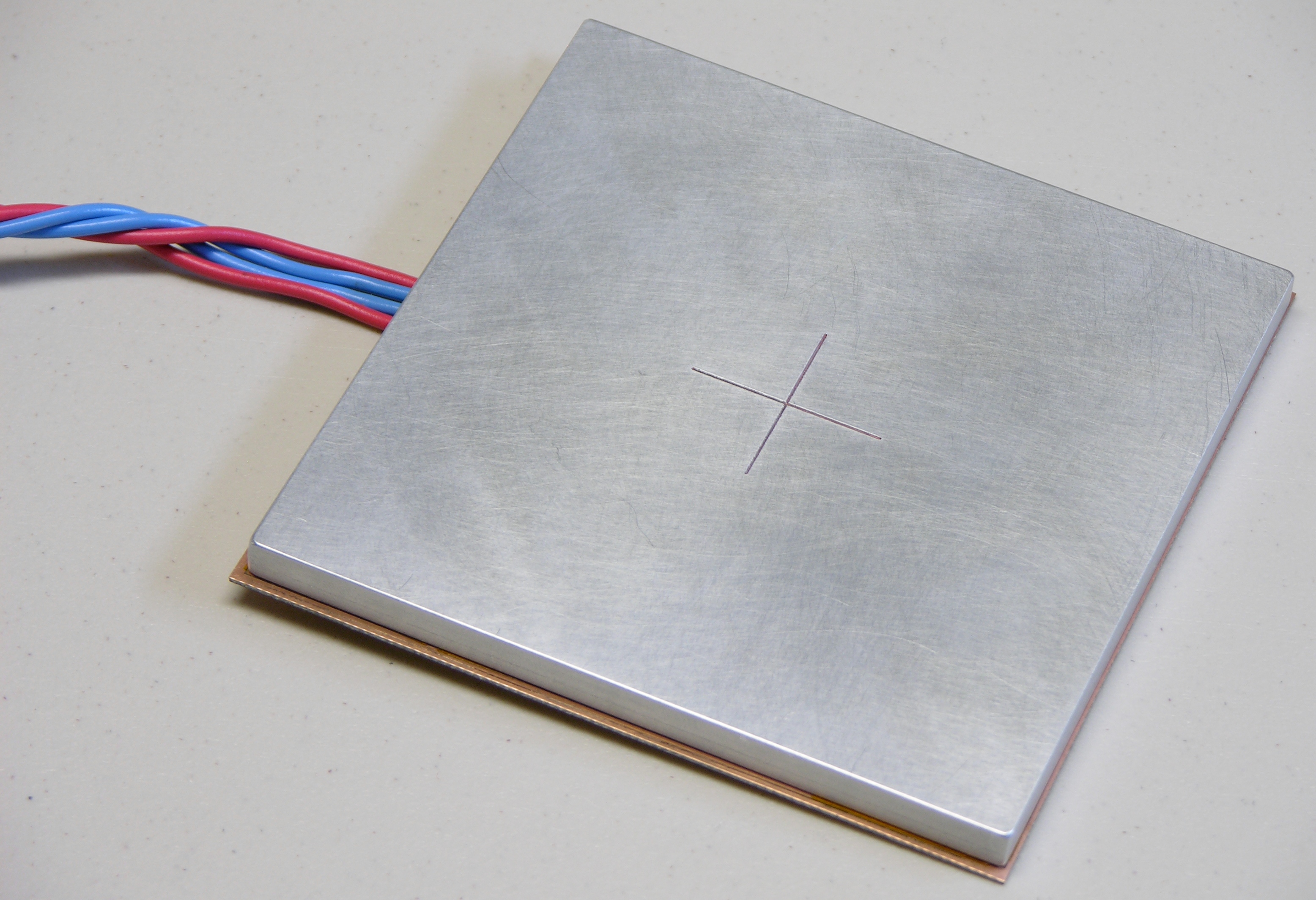
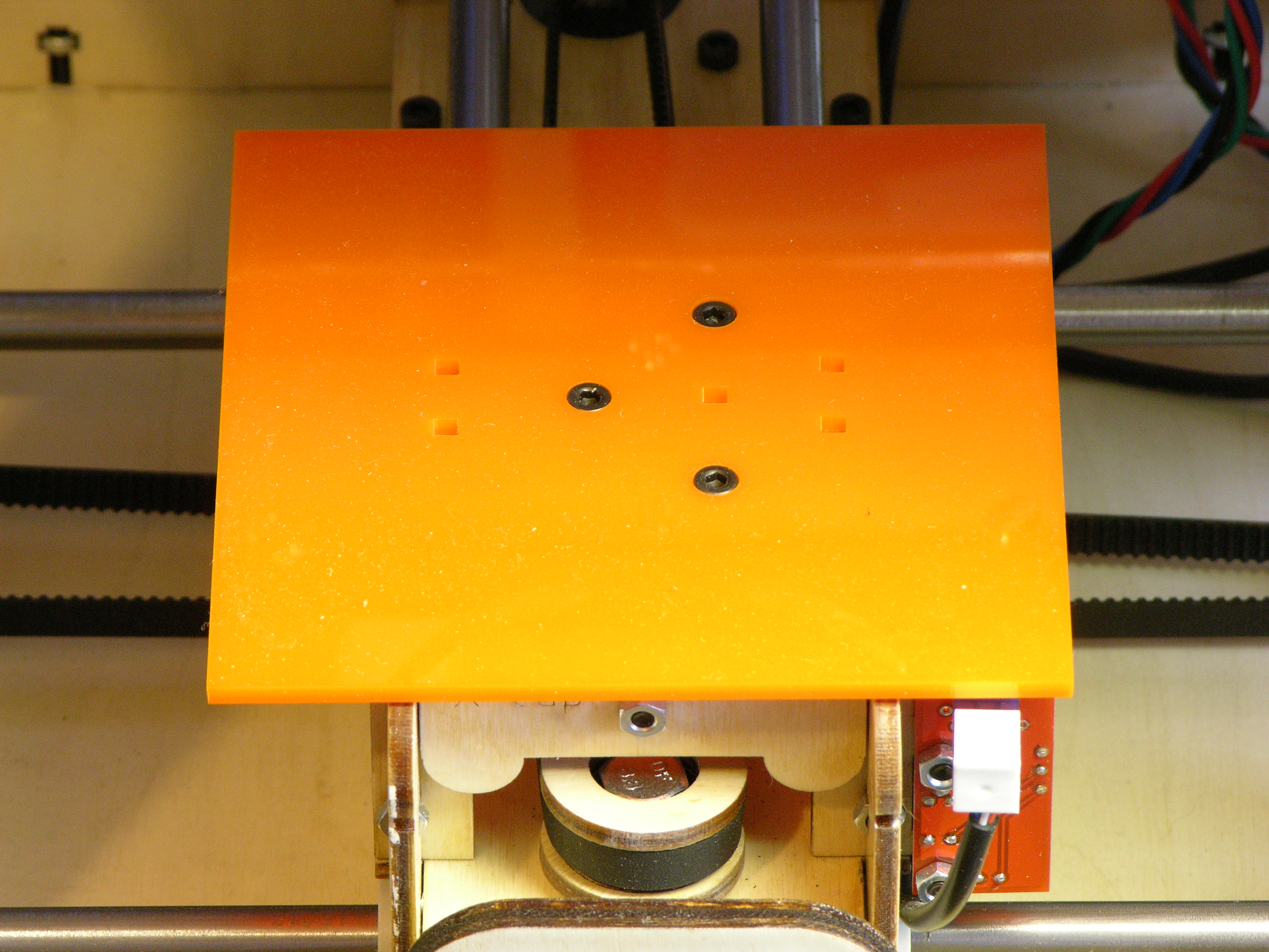
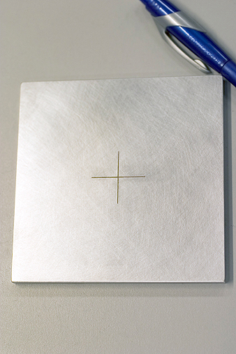
I had my acrylic insulator from Ponoko that press-fits perfectly onto the Y stage and the aluminum plate from Scott.

Acrylic base and milled aluminum plate for MakerBot CupCake heated build platform

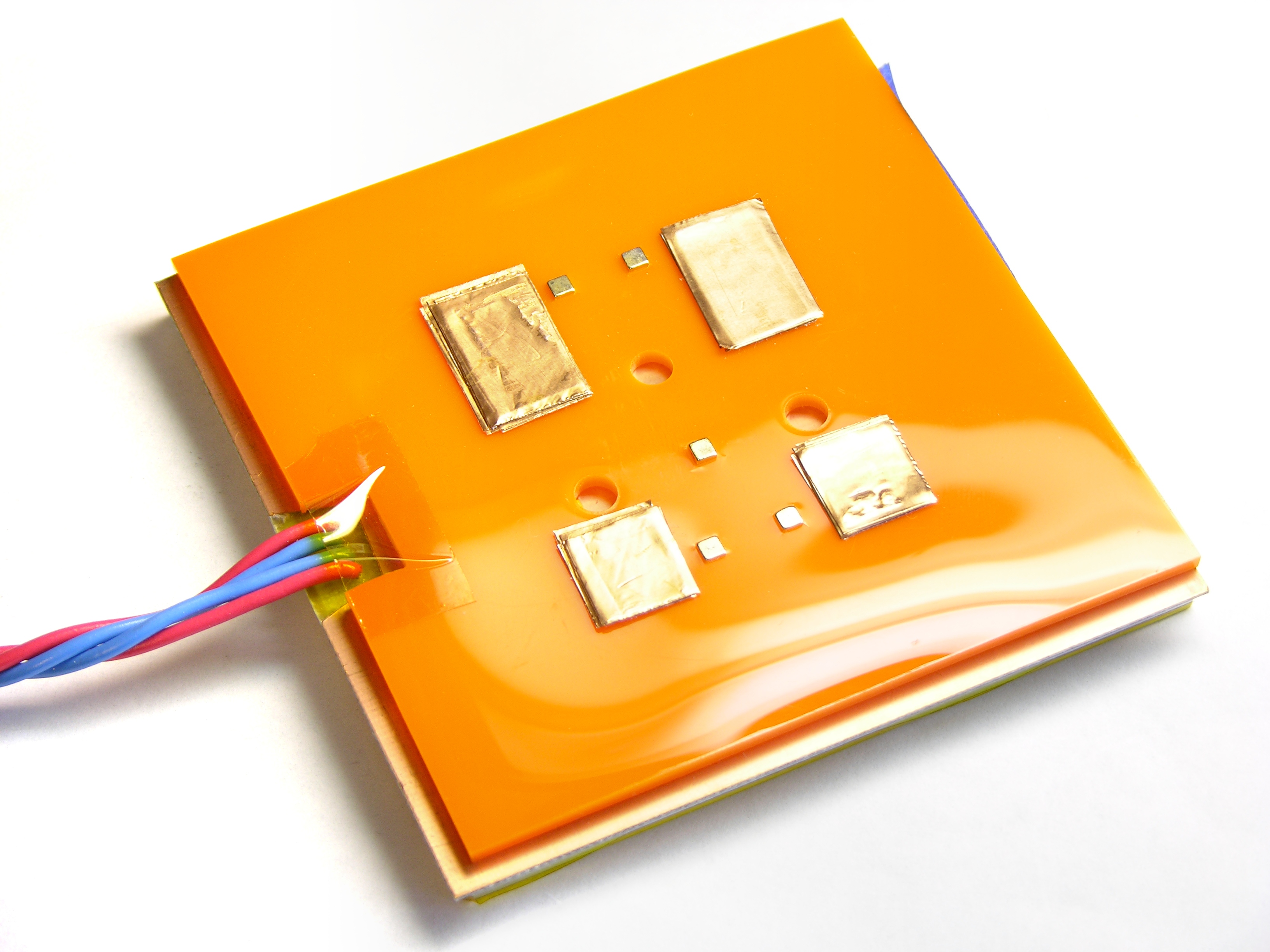
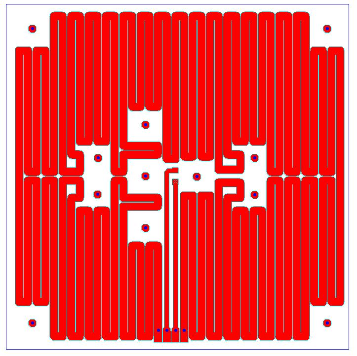
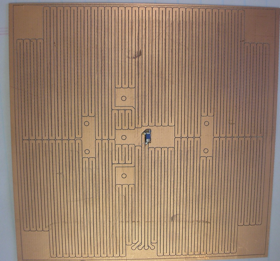
Scott had even milled a recess into the underside of the plate for the SMT thermistor Tom put onto the heater PC board; but because I wasn’t sure exactly what other features would need recesses and where, Scott left them for us to mill.

Two weeks ago Tom and I finally got together to assemble the heater, aluminum plate, and insulator into a tasty heater sandwich.

Tom McGuire milling recess in aluminum

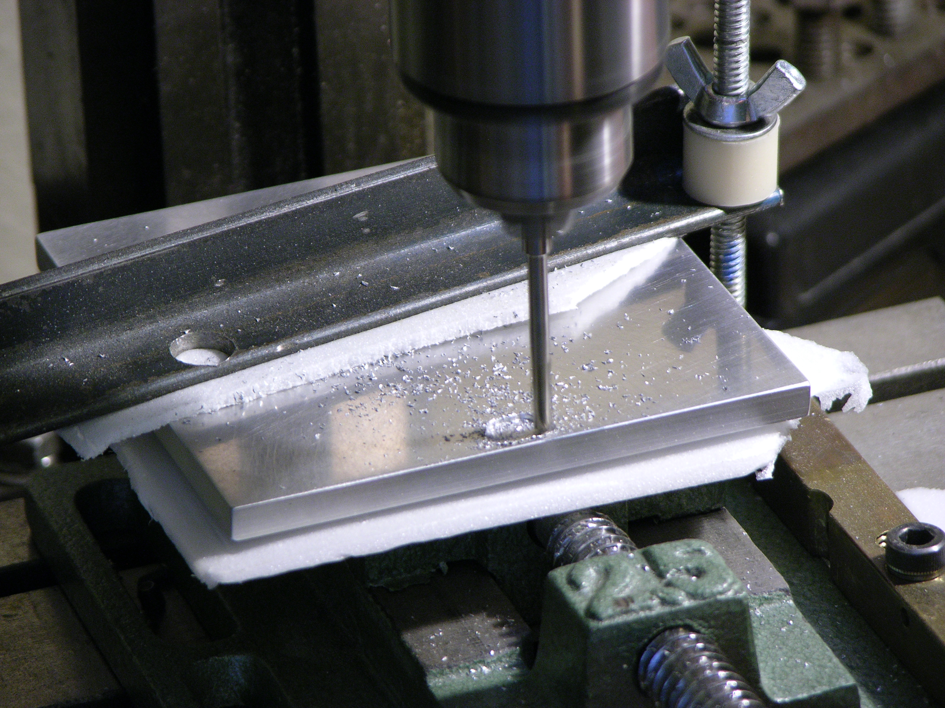
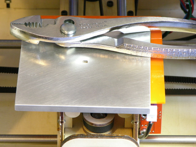
First I marked on the aluminum the location where the wires would connect to the PCB. Tom milled a recess into the aluminum to provide clearance for the solder joints on the top side of the PCB.

Milling recess in aluminum

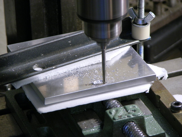
Tom did quite a nice job of milling a trapezoidal recess by hand without any CNC assistance, and was careful to protect the surfaces of my milled plate.

Heater PC board with double-stick kapton tape

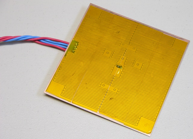
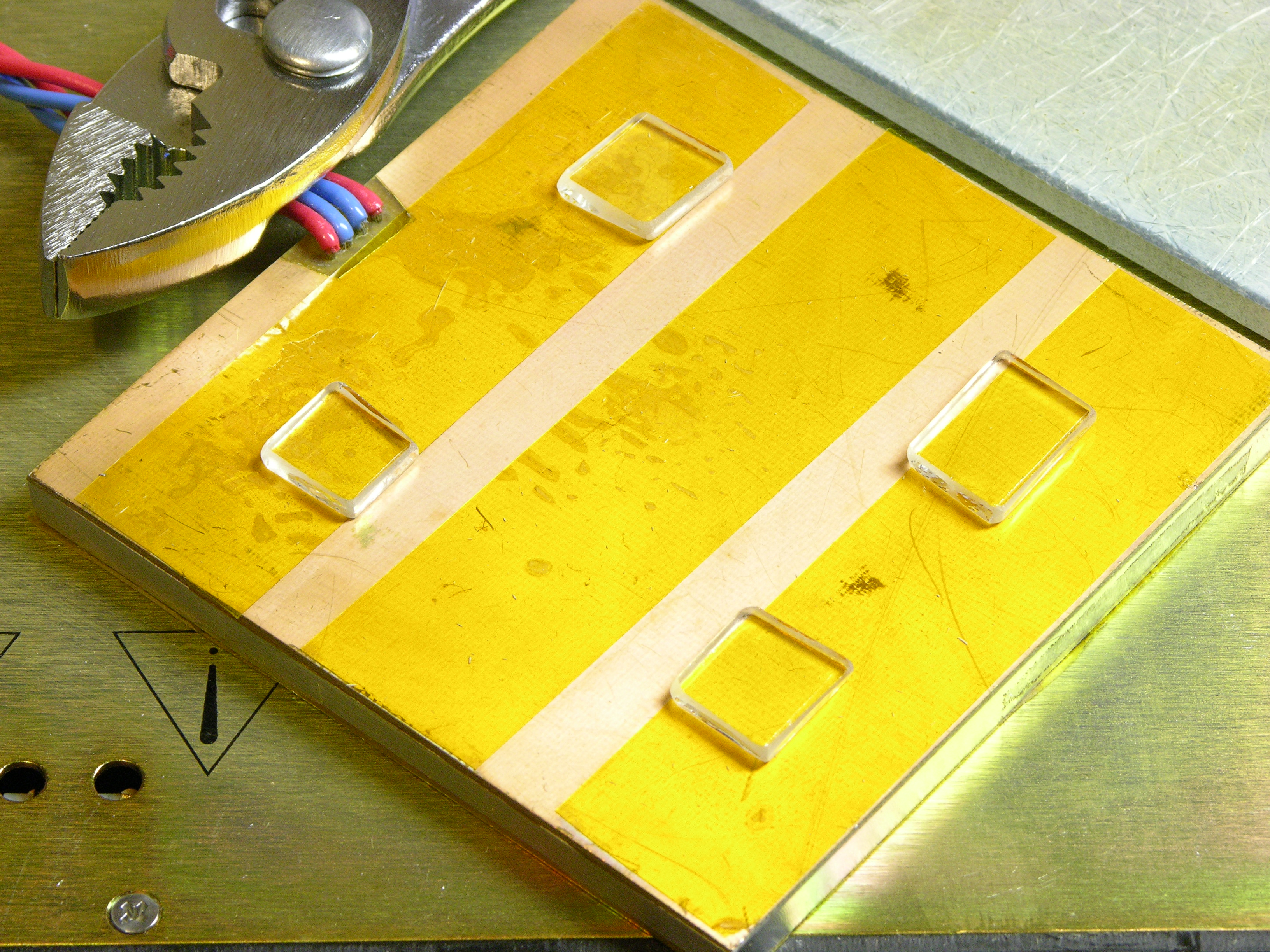
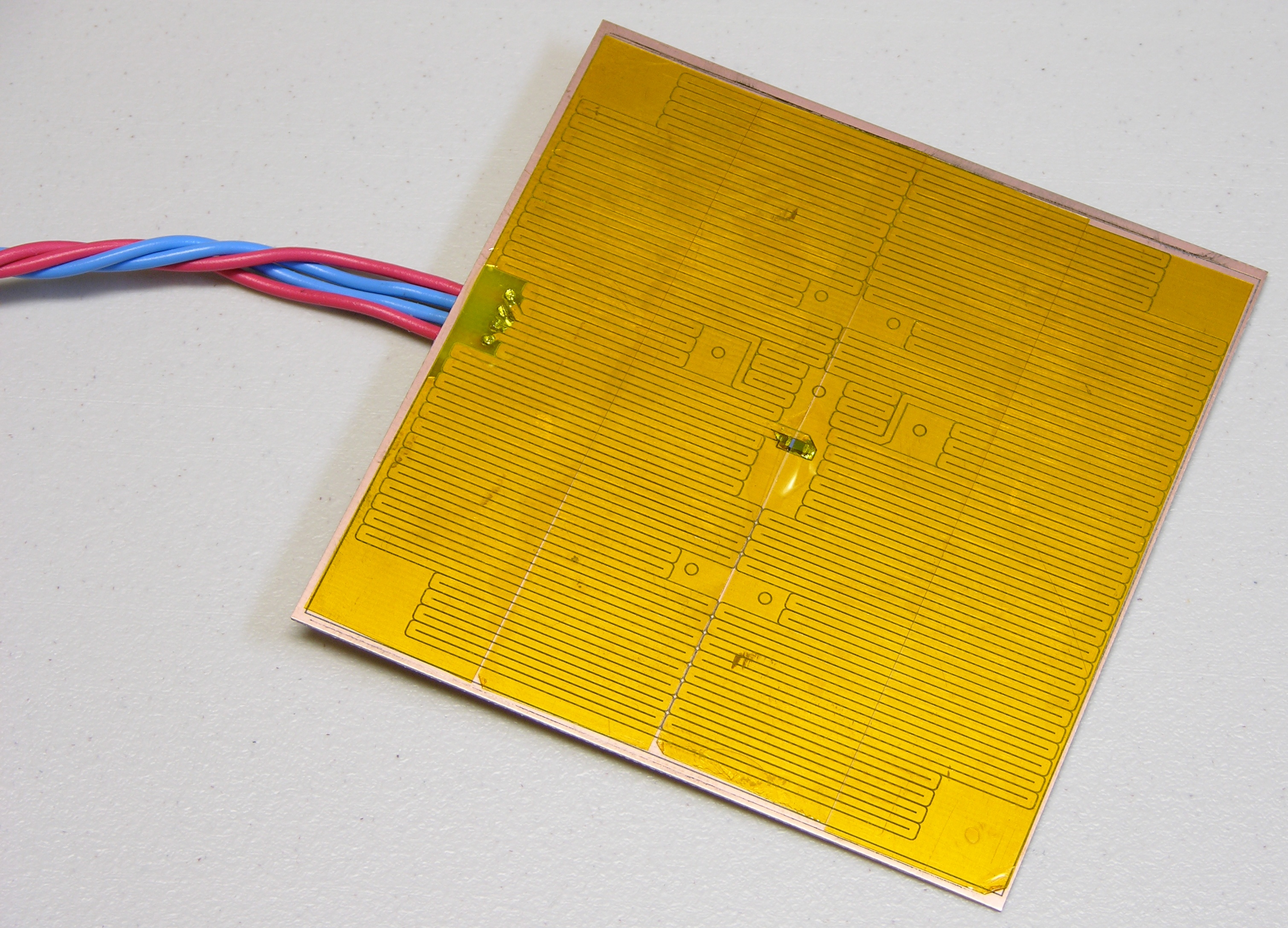
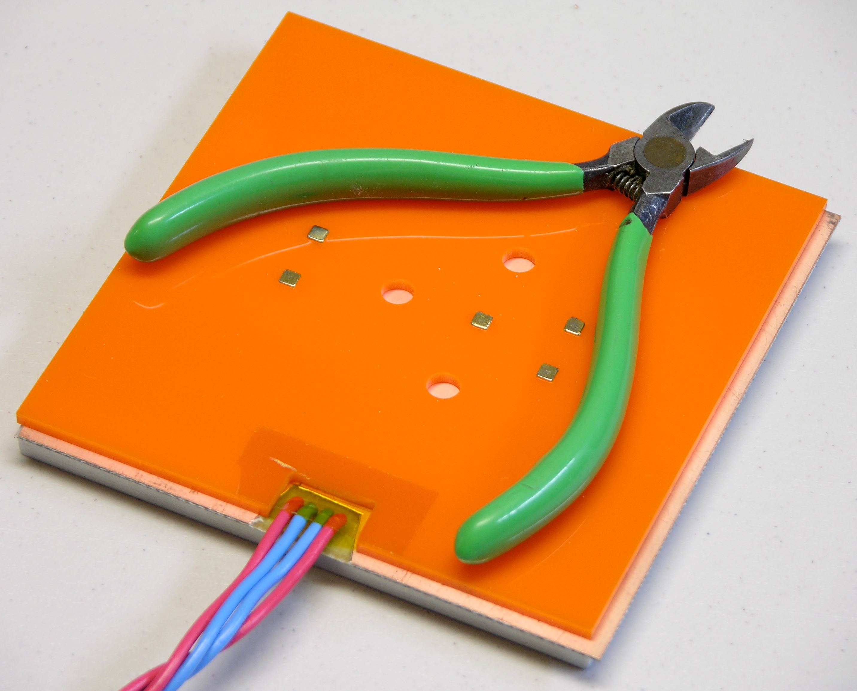
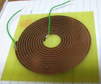
Tom soldered wires to the heater PCB. After confirming that the heater resistance was still about 4Ω at the far end of the leads (the same as the resistance of the heater trace on the board) to make sure we hadn’t shorted anything, we covered the PCB with double-stick kapton tape.

Aluminum plate attached to PC board heater for MakerBot CupCake build platform

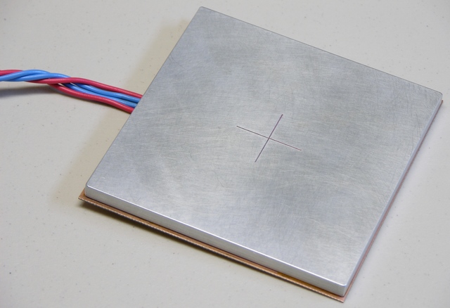
The PCB was slightly oversized, so I had fit the pieces together first to mark the correct alignment. I set one edge of the aluminum into place on the double-stick tape, leaned it down and rechecked alignment against my marks, then pressed it into place.

Besides holding the pieces together, the tape insulates the PCB traces and the thermistor from shorting on the aluminum. We re-measured the heater resistance at 4Ω just to be sure we hadn’t shorted anywhere.

MakerBot CupCake heated build platform underside showing wire routing

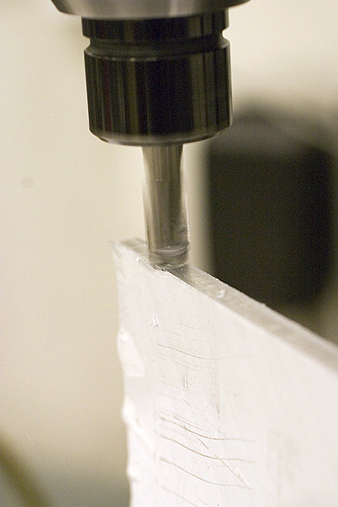
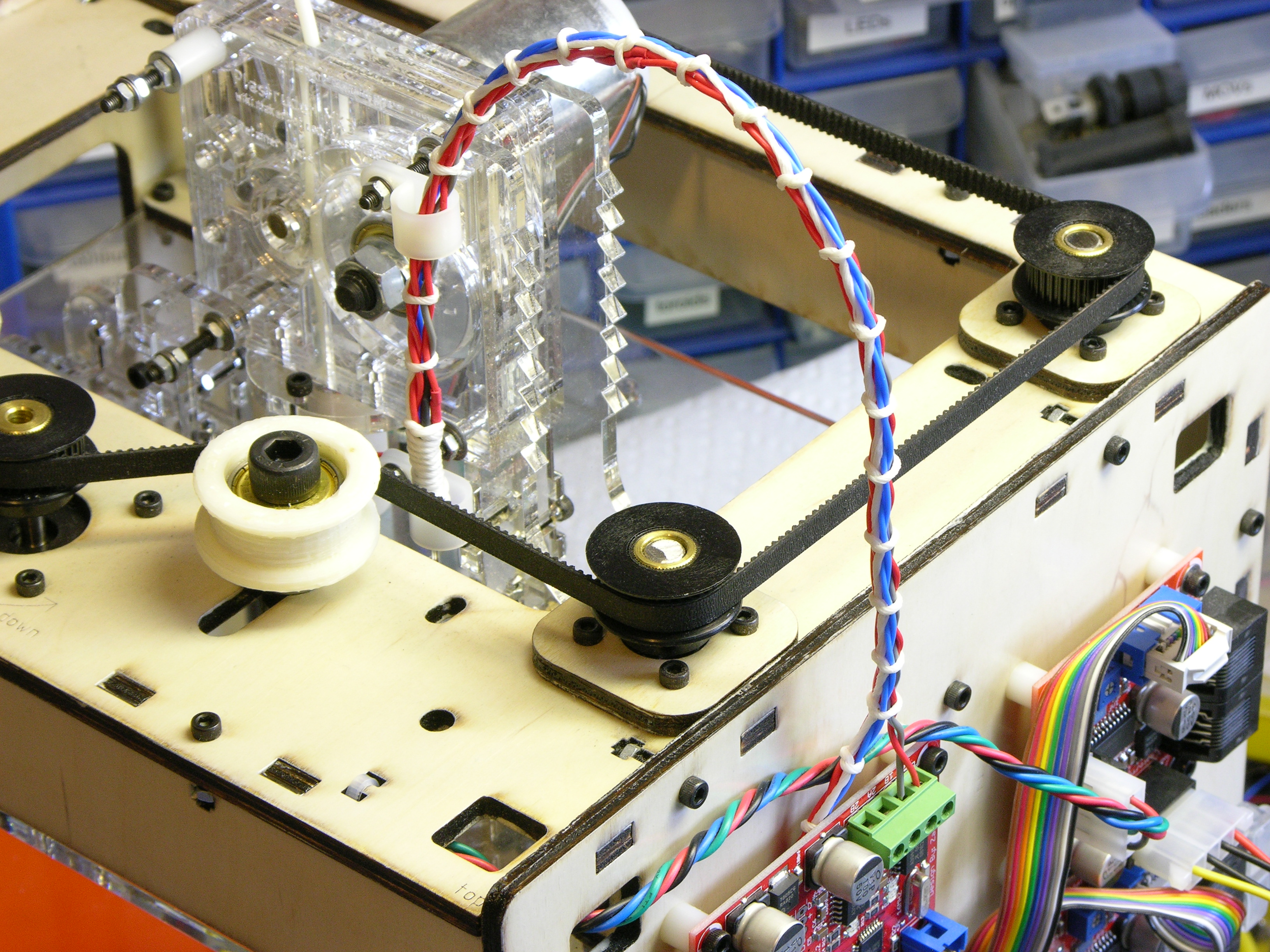
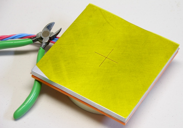
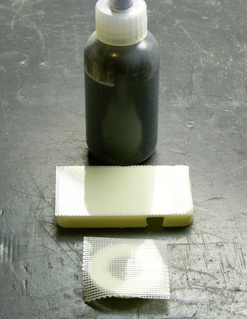
While Tom was milling the aluminum, I had marked, cut, and filed a notch in the acrylic to route the wires out the back of the heater assembly.

We attached the acrylic to the sandwich in similar fashion and put a little piece of kapton over the wire recess, more for show than because it actually provides much holding power. I could fill the recess with a heat-safe gasket compound, but the wires have been doing okay so far and I like knowing I can disassemble this for repair or upgrade.

Note how Tom peeled the copper off the back side of the PCB around the wires’ through-holes.

MakerBot CupCake heated build platform with sloppy kapton tape surface

I hadn’t realized how difficult it would be to apply 4″-wide tape to a square platform. The 1-mil tape is really schlimmery and hard to align straight where it first touches and grabs onto the aluminum, hard to squeegee down without bubbles, hard to press down straight without creating wrinkles, etc. I’m pretty good at squeegeeing screen protectors onto PDAs straight and bubble-free using a credit card, but the kapton tape was having none of that. An edge of the tape also tore coming off the roll. (It looked like it was bunched up where it had been sheared at the factory.)

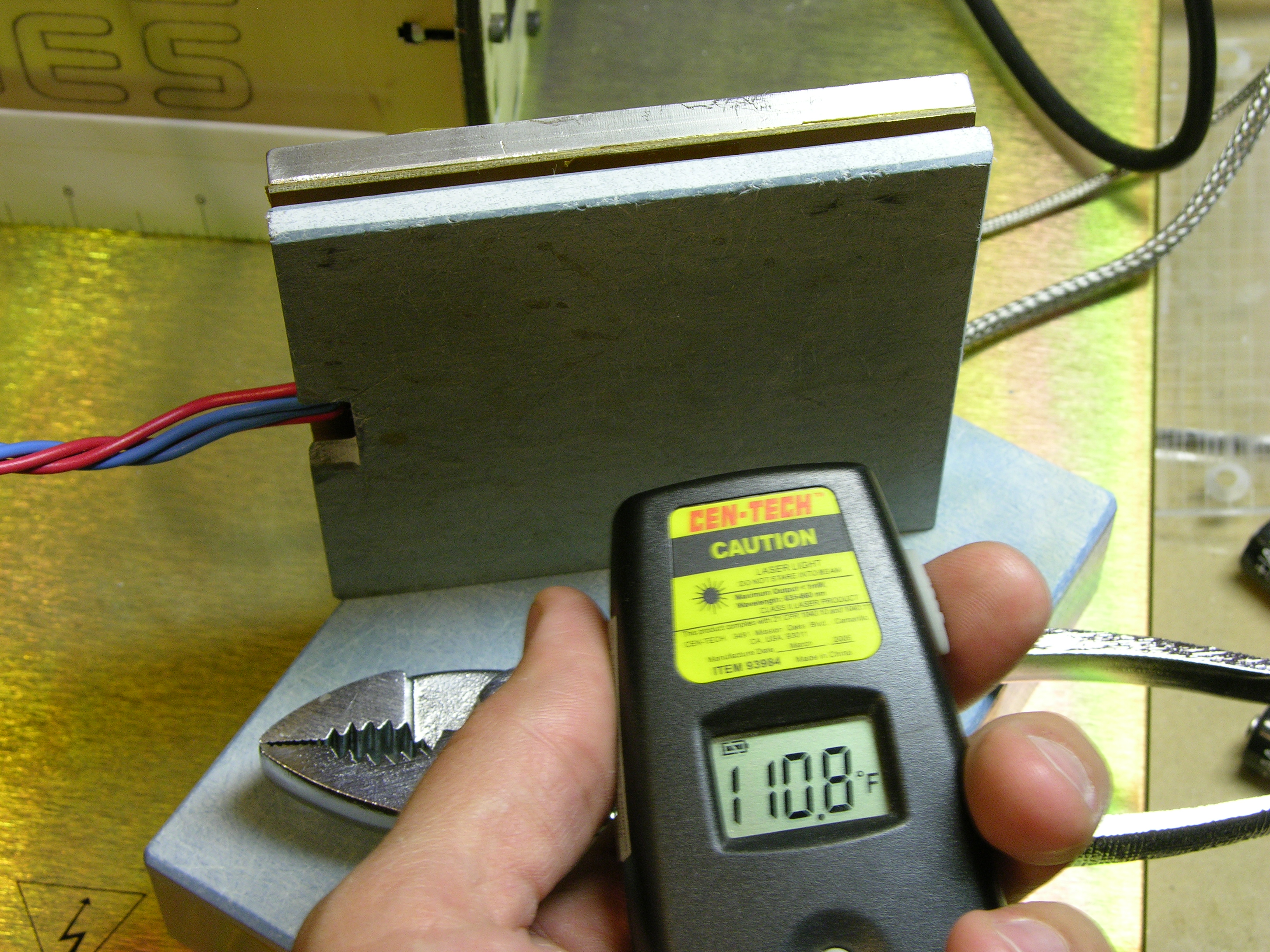
Oh, and it didn’t help that the aluminum was still hot from a test firing and Tom and I were both halfway juggling it trying to hold it and the tape. :-)

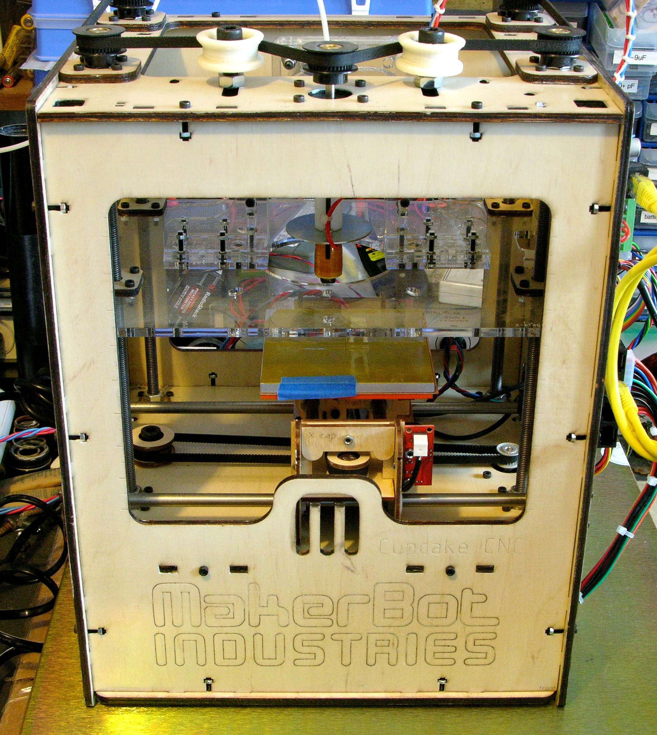
Printing on the Heated Platform

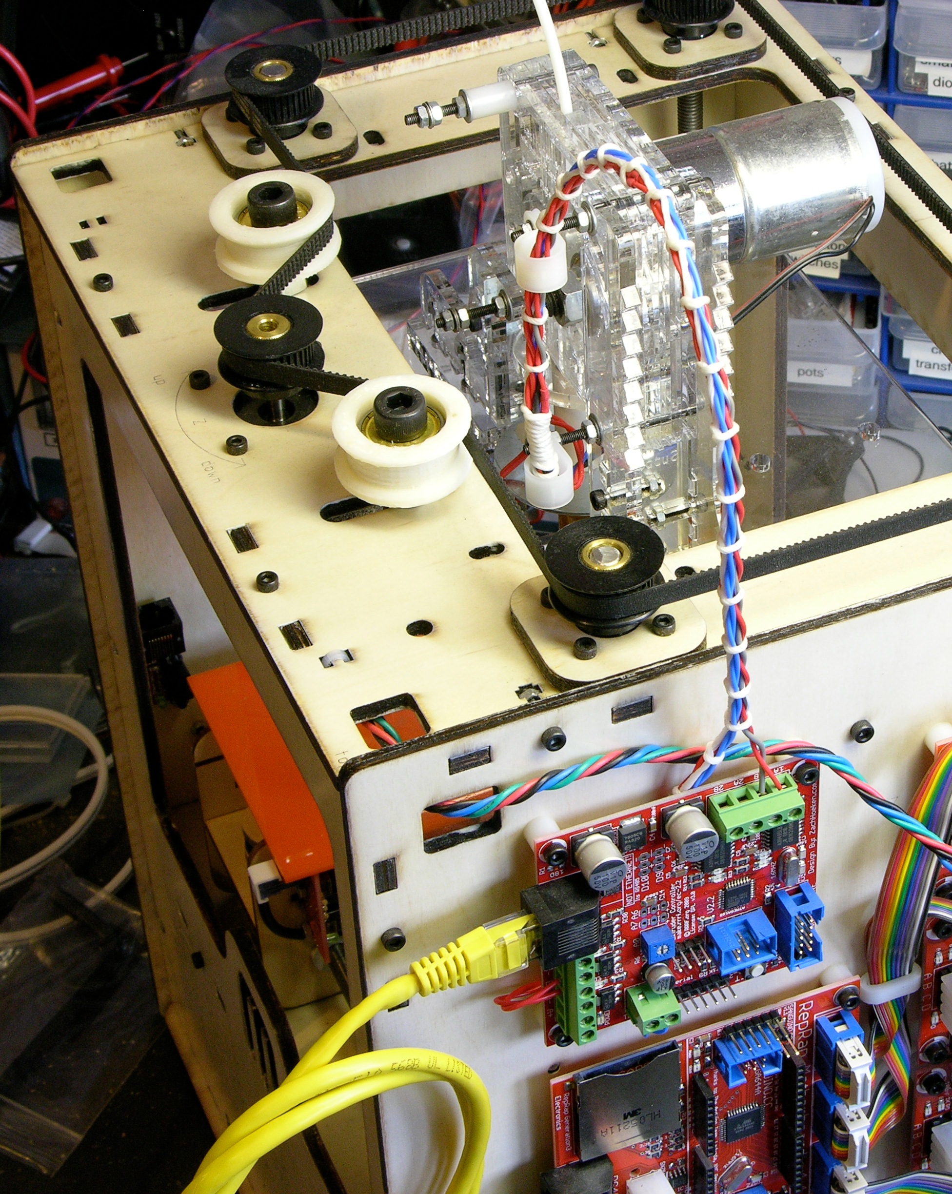
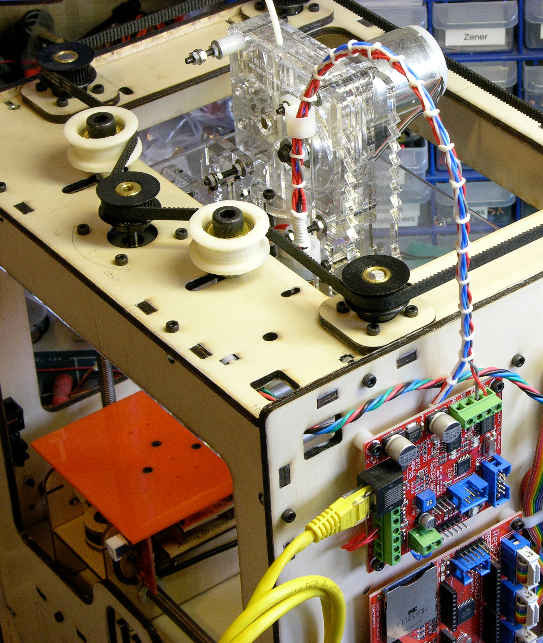
Many folks building heated build platforms are powering them from the extruder and hacking the firmware to control the platform temperature. I’m not averse to this idea in the long run; but for expedience, I brought a variable power supply and we used it to power the new heater.

Tom ran the supply up to about 24V to heat the platform quickly and then dropped it back to 12V to maintain a fairly steady temperature somewhere in the 180-200°F range. (It wasn’t varying that much; I just don’t remember exactly where Tom set it.) The power supply’s current meter showed a reassuring V / 4Ω the whole time.

Partial pulley extruded onto heated build platform showing pliability of raft

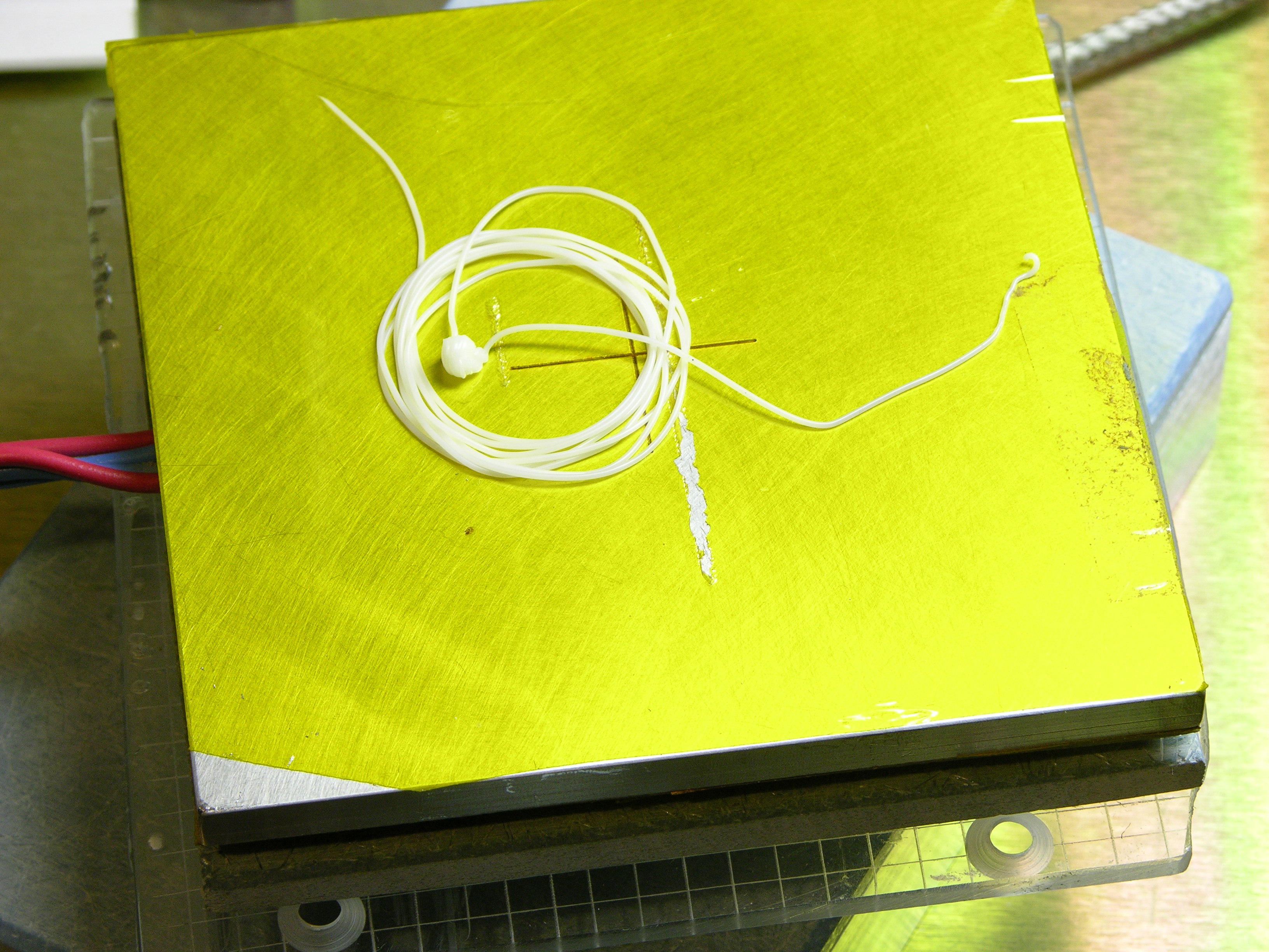
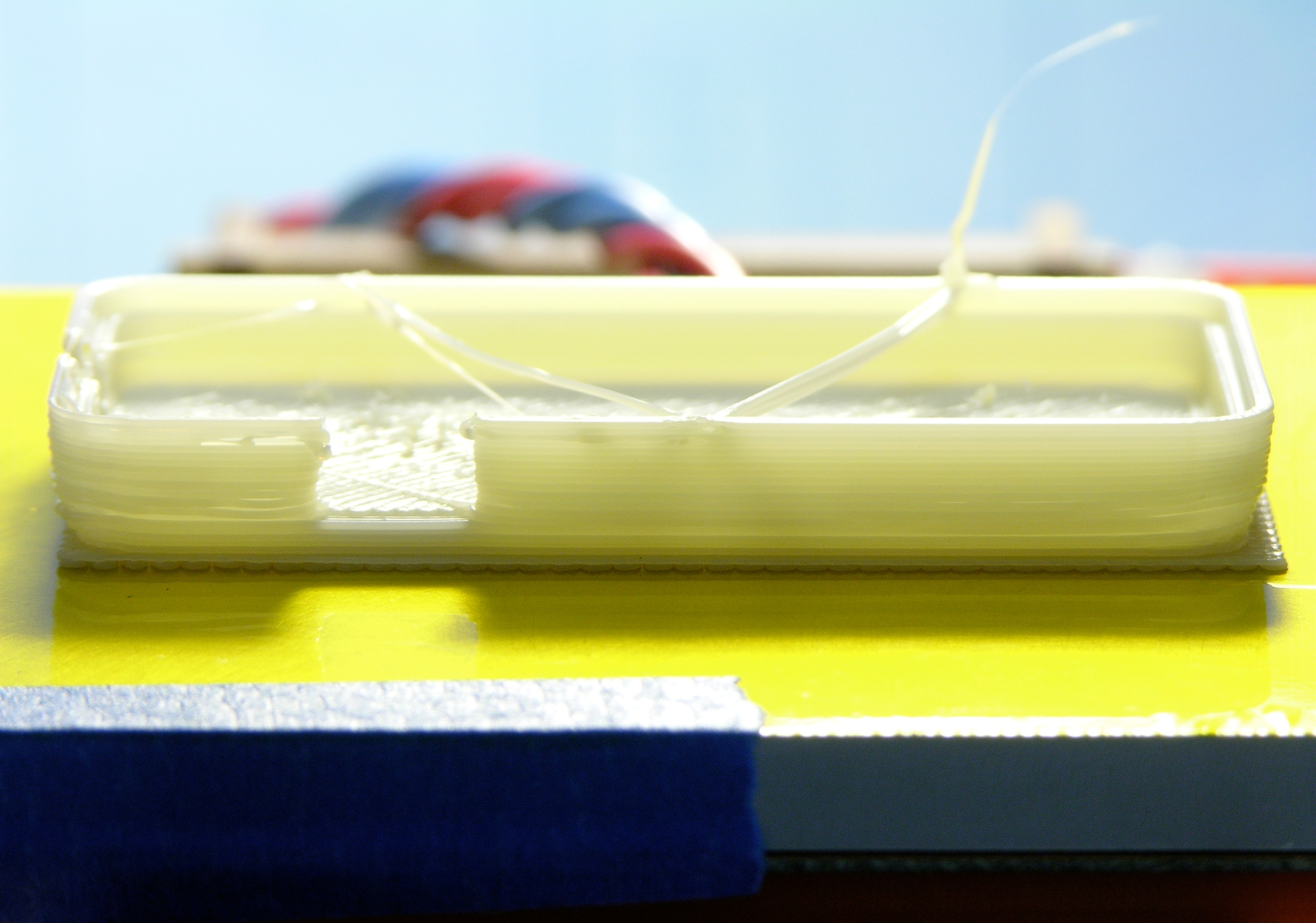
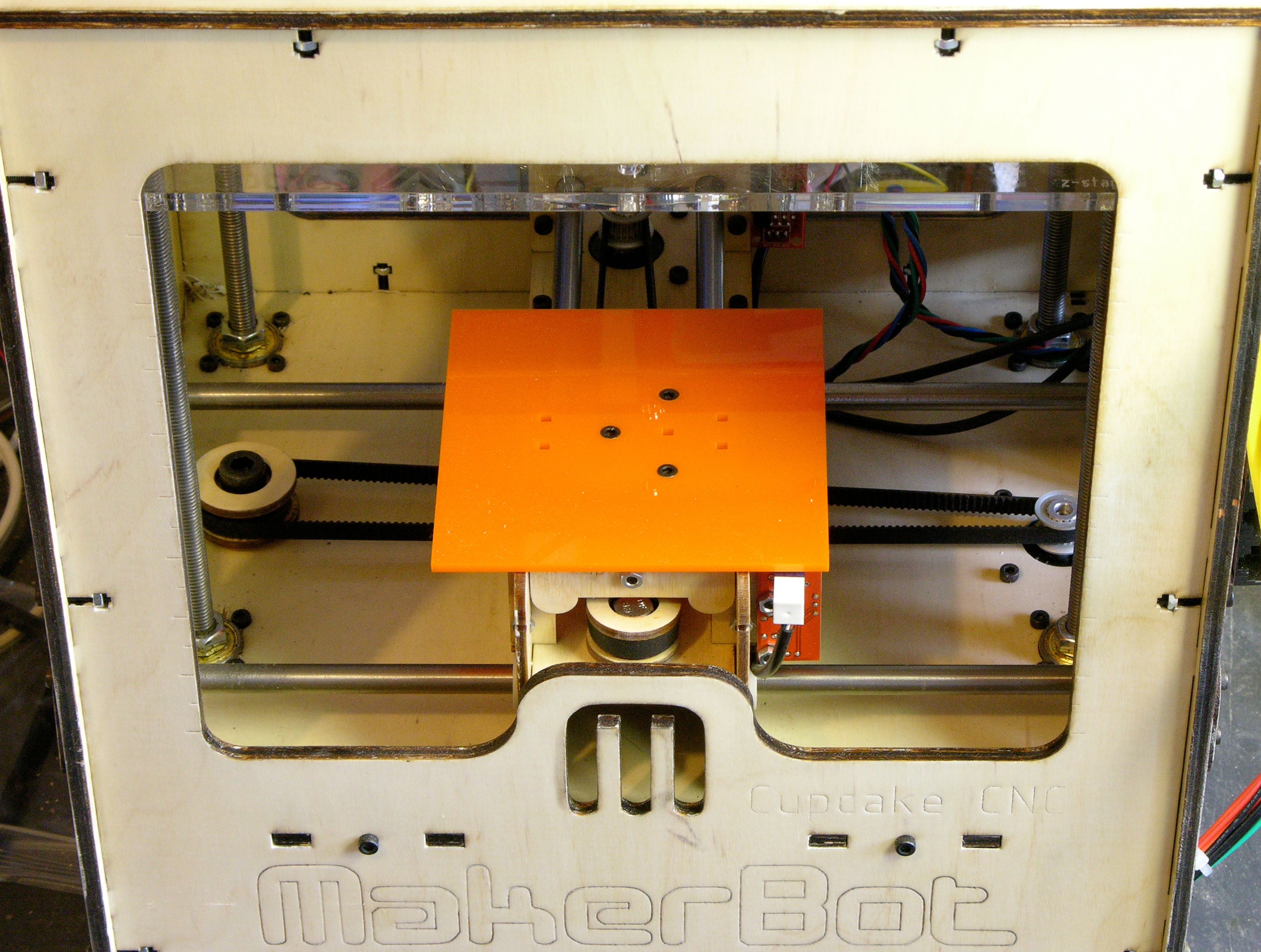
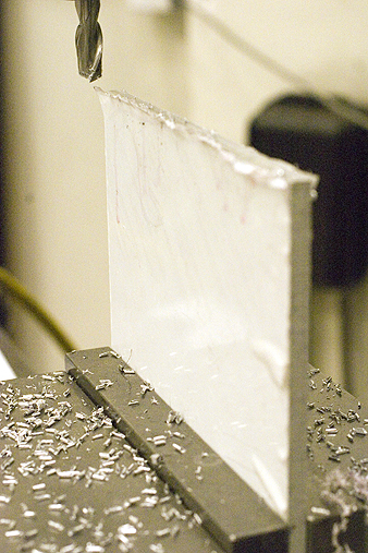
The first printing attempt was Zach’s idler pulley. I have other settings wrong (the perimeter density is too low), but the raft adhered perfectly to the kapton. The lifted corner is where I started to peel up the still-pliable ABS without having let the platform cool quite enough.

Tom added the blue tape, by the way, to create a non-specular surface for the IR thermometer we were using.

Fob case extruded onto heated platform -- no warping!

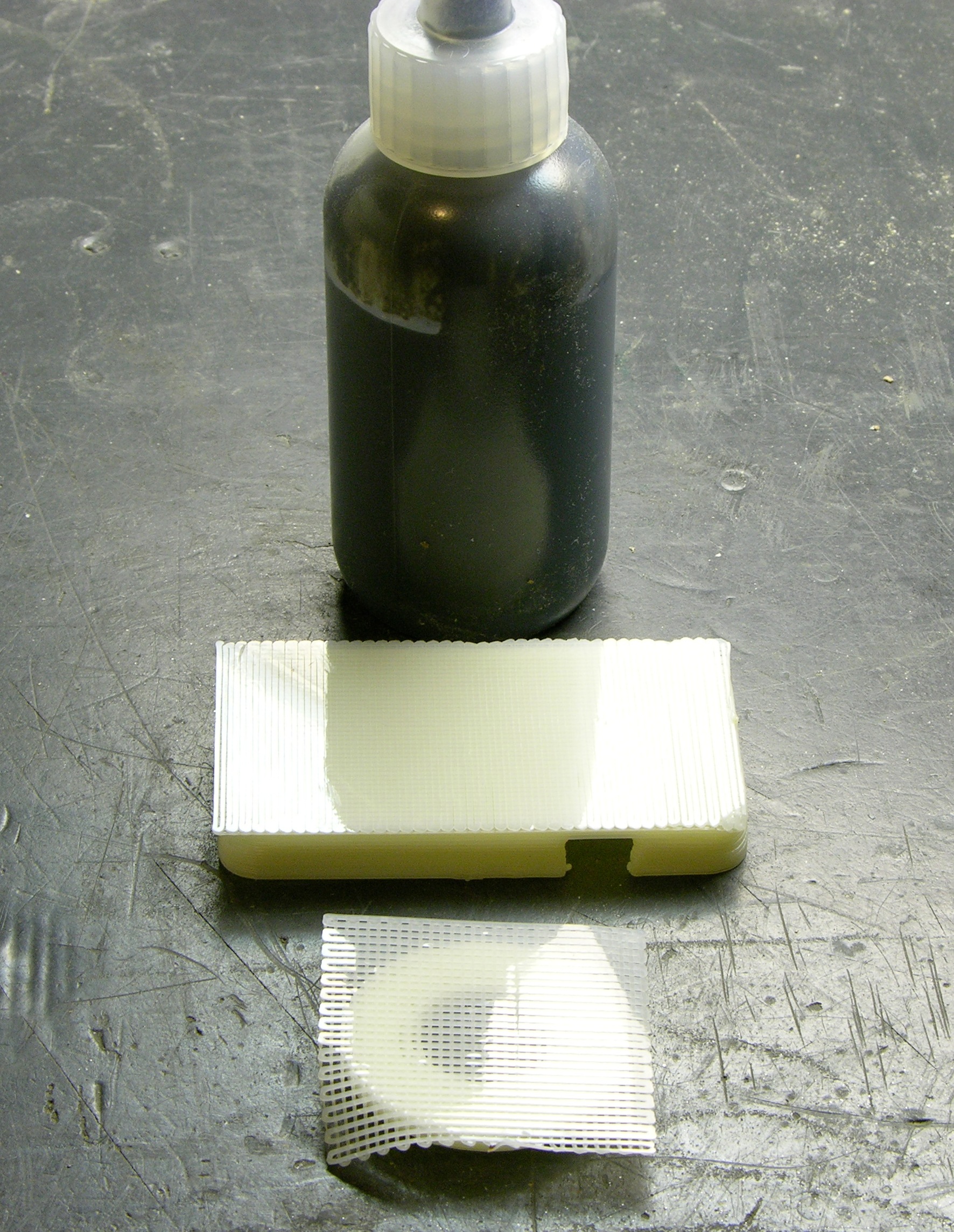
Skeinforge had some wacky ideas and my densities were off again, but a fob case built perfectly flat with no lifting or warping as well. I let the fob cool longer than I had the pulley before trying to remove it, and it popped right off the kapton with only slight deformation in the corner where I wedged the knife blade (still too soon).

reflections off raft bottoms

As nophead did on his initial tests, I got delightfully smooth and reflective surfaces where the ABS conformed to the hot kapton.

Next Steps

Living in Times of Raft-Free Printing

As zaggo described in Living in Times of Warp-Free Printing, I no longer need to print a raft under my builds. I’ve not yet installed the Skeinforge Raftless module, which prints a leader into the first layer to give you time to fine-tune the nozzle height (and amount of extrusion squish) and slows down the feed rate of the first layer to help smoosh it onto the platform. But with judicious live Z-axis tweaking, I’m getting reasonably good results.

Flatness and Leveling

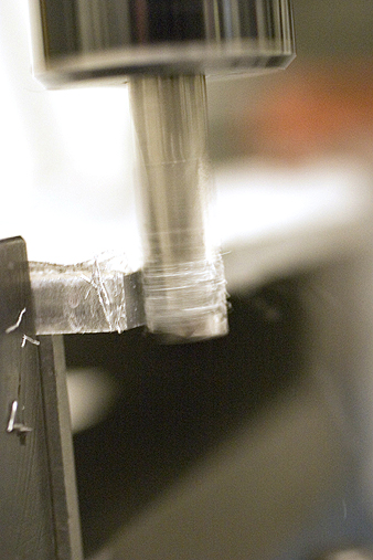
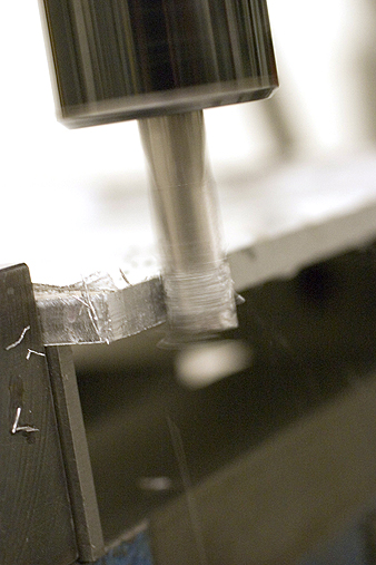
The aluminum plate appears to be dead flat, as it should be (and as I had hoped). It is not, however, dead level with (parallel to) the X and Y axes, causing the first layer of large objects to be tightly smooshed at one edge and not quite sticking to the platform at the other edge.

Copper tape on underside of MakerBot CupCake heated build platform

Tom and I stacked copper tape scraps on the underside of the platform in a quick and dirty attempt to level it, but the copper tape appears to be just squishy enough that it probably won’t provide reliable leveling.

Worse, you can see that the heater gets a bit too warm for the acrylic and my “insulator” is starting to warp after only a few hours of use. I’ll need to add a sheet of real insulating material between the heater PCB and what I believe I shall rename the acrylic “mounting plate.”

Warped MakerBot CupCake Y stage

Also the left edge of the Y stage plywood is not fastened down to the walls, so there’s more play in the height / level of the left edge there. I’ll probably glue that together to make it rigid enough to use as a good base.

I’m thinking that nylon set screws in miniature T-nuts set into the Y stage may be the best way to level the platform. There’s not a lot of room to spare in the Y stage; I may have to cut a larger, replacement stage top. (Ponoko again.)

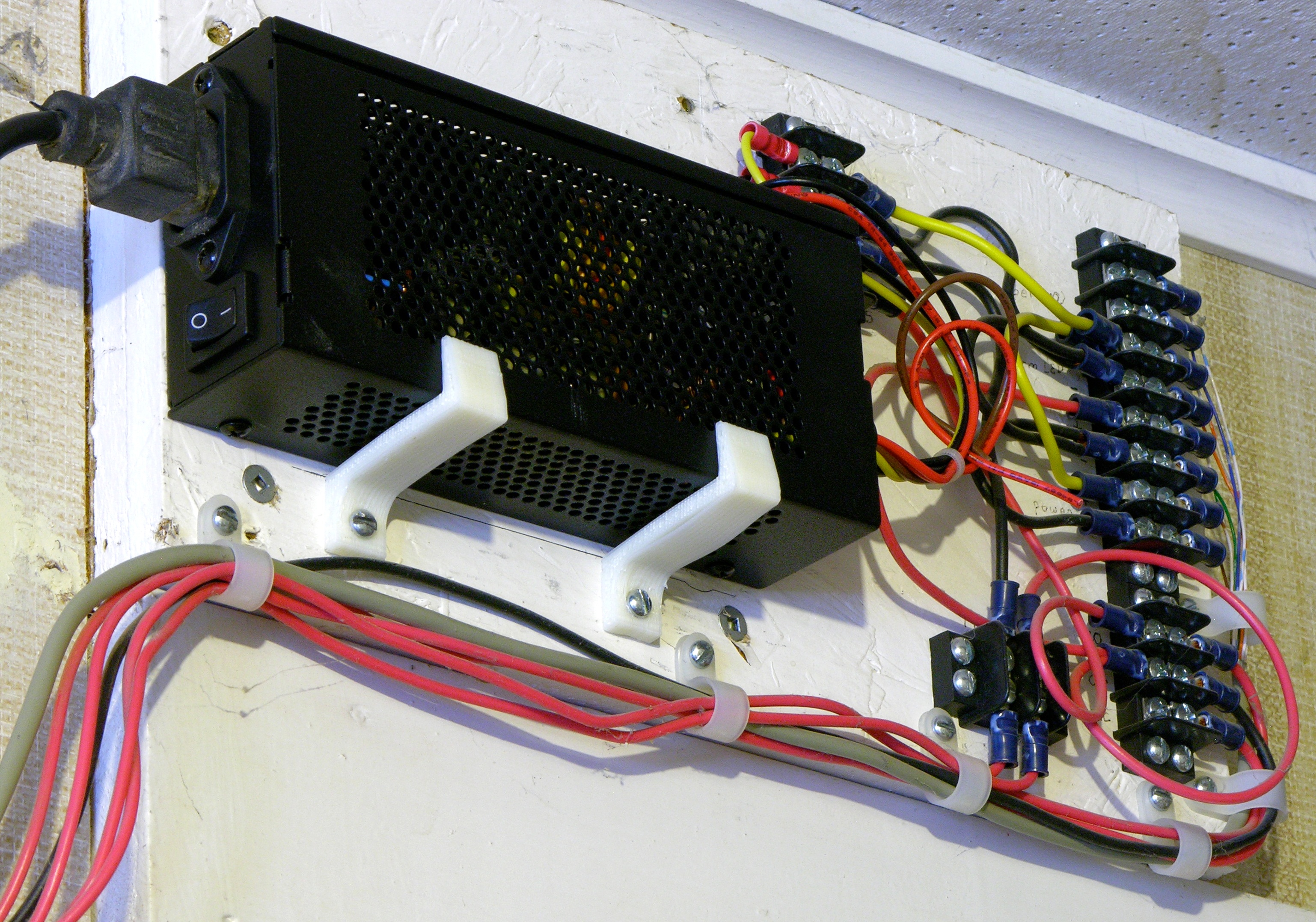
Thermistor, Power Supply, and Enclosure

I had assumed I’d use the thermistor for closed-loop feedback, but at Tom’s house 12V seemed like the perfect supply to keep the plate at the desired temperature and I considered wiring it straight to the PC power supply.

Since then I’ve used it in my colder utility room and had to turn the supply higher than 12V to get the plate warm enough. That suggests both that I will need to use the thermistor and that the CupCake’s PC power supply may not be an adequate power source for this heater. We may need to make a second PCB heater with slightly lower resistance — although I’m leery of increasing the heater current too much, lest the lead wires start heating up too.

MakerBot CupCake

Alternatively, rather than cranking up the power, I’m considering making plexiglass doors or panels to cover the CupCake’s openings and retain more of the heat from the platform. It seems like a more efficient approach; and it would also help warm the whole chamber, which should further reduce warping on objects that are both tall and wide.

Even though the extruder pokes through the top of the CupCake when at its highest elevation, quite a bit of the CupCake top could still be enclosed — and the Z platform itself nearly spans the CupCake interior, helping trap heat in the part of the chamber containing the heated platform and the extruded model. Again a good thing.

MakerBot CupCake Heated Extrusion Bed Part 3: Ponoko Laser-Cut Acrylic Insulator

Wednesday, March 10th, 2010

Looking back at my notes, I see I got parts 2 and 3 out of sequence; I actually sent off to have an acrylic insulating plate manufactured before Scott milled me the aluminum bed. No matter; I didn’t receive the package of insulators until well after Scott had sent the aluminum. :-)

Orange acrylic sub-bed on MakerBot CupCake build stage

After Tom offered and built me the McWire PCB heater, I was thinking about how best to attach it to the CupCake’s Y stage. The Y stage has M3 machine screw heads poking out the top, which are actually nice for maintaining registration of the build platform; and it has five magnets embedded in it to keep the platform securely attached to the stage.

Although Tom left clearance in the heater PCB for all of these things, I wasn’t sure I really wanted to have to drill through the PCB and into the aluminum plate to fit the PCB/plate sandwich onto the Y stage. I also didn’t think I really wanted to put a heater directly onto the Y stage. Even at temperatures not intended to melt the extruded plastic but only to keep it warm, I wasn’t sure whether the heater would scorch the wood, cause it to warp, or do something else undesirable.

While puzzling over how to attach magnets to the heated build platform, it occurred to me that I should simply do what MakerBot did in the first place — press-fit the magnets into lasercut holes. And the rest was obvious.

MakerBot CupCake build platform

Ponoko is an online service billing itself as “the world’s easiest making system.” You upload drawings in your choice of a couple of different vector formats, select materials, and confirm what you want done. They laser-cut your drawings and ship you the results.

Out of the wide range of materials they offer, I settled on acrylic. Its melting point is close to that of ABS and the heater isn’t supposed to melt the ABS, just slow its rate of cooling. The heater PCB’s heating traces are on the top side, so there’s a thin layer of fiberglass substrate between the heating element and the lower surface. Acrylic is supposed to be a fairly good insulator, which not only helps protect my wooden Y-stage but also should make handling the heated platform easier. And they had it in 3mm sheets, which turned out to be exactly the dimensions of the magnets. (In retrospect, I’d probably use 5mm next time and let the magnets “disappear” into the interior of the sheet’s thickness.)

To prepare for Ponoko, I downloaded the same CupCake Y-stage DXF file from Thingiverse that I had sent Tom to find the hole spacing for the heater PCB. I installed a demo copy of QCAD and in a single one of the 10-minute sessions its demo allows opened the DXF, deleted everything from the Y-stage file but the build platform, moved the platform to the origin, deleted the lettering from it (because it’s no longer a build platform), and saved it as an SVG. (Whew!)

Rambling sidebar: By the way, I interpret the CupCake’s CAD files’ CC-GPL license as indicating that I may legally copy the CAD files and make derivative works. CC-GPL refers throughout to programs and it’s not clear how it applies to designs for physical objects; but also it takes effect not when you modify but when you distribute modified works. The original MakerBot build platform does not contain a copy of the GPL as it would be required to were it a program being distributed under the GPL, thus I don’t think that my insulators need to contain a copy of the GPL even if I distribute them, as they would if they were programs. However, I want to be true to the spirit of the license attached by the creators; and if this works out, I’m glad to make available the SVG files I created and used.

MakerBot CupCake heated build platform insulator, single

I loaded Ponoko’s “P1″-sized template into Inkscape, imported the modified platform SVG I had saved from QCAD, changed its line color and width to the settings Ponoko uses to indicate cutting (versus etching), and saved a copy. I uploaded it to Ponoko, selected 3mm acrylic as the material, and ran through a shipping quote — which due to an incorrect default setting on my Ponoko account was going to make the part in New Zealand and ship it to me at a cost of about $80.

MakerBot CupCake heated build platform insulator, 3x3

While I was straightening that out, I loaded a “P2″ template and placed nine insulators on it. (Although I left more space between copies than I needed, there was definitely not enough room to get four copies along either edge.) I got my “manufacturing country” set correctly and ran an estimate on the 3×3 P2 version.

size make material shipping total yield each
P1 $.83 $2.50 $5? $8.33? 1 $8.33?
P2 $7.73 $8.66 $9.88 $26.27 9 $2.92

I don’t think I reran shipping on the exact P1 shown above, but I had run another P1 and got shipping in the $5 range. So I could get one insulator for ~$8 or nine for $26.27 ($2.92 each). I submitted my P2 order for nine insulators.

I was shocked to see an estimated delivery time of four weeks — it didn’t seem like it should take that long to slip a sheet of plastic into a laser cutter, run my design, and throw it in the mail. But I think Ponoko is doing well and has a lot of business, so it makes sense that they’d have a backlog.

Ponoko package

Ponoko sent me updates as my order was being validated, prepared, cut, and packaged. It shipped two weeks after I uploaded my file and arrived about a week after that. Opening the package was a bit anticlimactic — the protective paper on both sides of the plastic is rather boring to look at and visually disappears into the shipping cardboard. But I had lovely orange parts inside!

Orange acrylic sub-bed on MakerBot CupCake build stage

I had originally thought that the kapton tape I intended to use on top of the aluminum plate would look oranger than it ended up, so I had tried to find an orange translucent acrylic to match it, but it was out of stock. I picked the orange opaque, which I find rather striking, and probably like better than the yellow translucent I would have picked had I had my tape on hand already.

The acrylic insulator press-fits perfectly onto the machine screw heads — it feels like I wouldn’t even need the magnets to hold it in place!

MakerBot CupCake Heated Extrusion Bed Part 2: Milling an Aluminum Plate

Tuesday, March 9th, 2010

On January 5, nophead wrote of his serendipitous discovery that ABS sticks well to hot kapton tape and releases well from warm kapton tape. Coupled with difficulties I’d been experiencing with my plexi build platform not being rigid and flat enough, I knew immediately that I wanted the top of my heated build bed to be aluminum plate covered in kapton.

When Tom McGuire built me a PCB heating element, he offered me some sheet aluminum for the top; but although not thin, it wasn’t thick enough to be as rigid as I wanted it to be. I contacted my friend Scott Smith who has taken up machining and he offered to mill me a piece from some 1/4″ plate he had on hand. I sent dimensions and he did the rest, including taking pictures and sending me the following commentary.

February 6:

Having rough-cut a 100mm square piece of polished flat 0.25″ aluminum on the band saw, it’s time to square off the edges.
Milling first square edge on aluminum plate

After one edge is flat, I can flip the piece over and mill the opposite side. Once done, I have at least two sides that are guaranteed parallel.
Milling parallel edge on aluminum plate

When I rough-cut the piece, I left some extra so that I could square the piece off without losing too much material. Now both sides are parallel.
Milled parallel edge on aluminum plate

Next, I lay the piece flat in the vise with the non-parallel edges on the left and right sides. I can run the mill in the Y direction to square these last two edges off.
Squaring third and fourth edges on aluminum plate

Using a macro lens in rather low-light, so I had to crank up the ISO and open up the aperture. Still, my shutter speed was too slow to catch individual chips flying around…
Chips flying while milling aluminum plate

Once the piece is square, I use an edge finder to zero out the CNC at the center. The stop is placed in the vice so that when I flip the piece over, I don’t have to re-center the CNC again.
Aluminum plate in vise with stop

The crosshair is made using an 60 degree engraving bit at high speed.
60-degree engraving bit

To zero out the Z axis, I wiggle a piece of paper back and forth under the engraving bit as I slowly lower the spindle. When the paper stops moving freely, I set the Z position to the thickness of the paper.
Lowering engraving bit to aluminum plate

After engraving there were burrs around the crosshairs. Before I use Scotch Brite to clean it up, I take a red sharpie and ink in the grooves.
Inked crosshair grooves in aluminum plate

The Scotch Brite takes any excess ink off of the surface, but leave the ink in the grooves. Hard to see in this photo, but the crosshair is red.
Deburred aluminum plate with inked crosshair grooves

MakerBot CupCake Heated Extrusion Bed Part 1: McWire PCB Heater

Tuesday, March 9th, 2010

Over the holiday break, I had written about using a hairdryer to heat my CupCake build chamber.

On January 11, 2010, Tom McGuire wrote:

Hey Keith, I haven’t caught up with your blog for some time. Looks like you got a lot done in the last couple weeks. It’s good to see you’re getting results from your CupCake.

Can I help you with a hot plate? I could make you a thin aluminum plate about 4″ square that gets up to 200°C. I guess you would need it to be insulated on the bottom to keep from burning your stage. Do you have a low voltage with lots of current available, say 12V @ 10A or may be 5V @ 20A. What do you think?

What did I think??? I thought it sounded great! The heated chamber was helping my prints, but I was still getting some warp. I knew a heated platform was the way to go and it had been my goal all along.

Spiral PCB heater

We started discussing the way other folks were making their heated platforms and Tom went on to say:

Oh 100°C would be no problem for PC board material. I was thinking at first to place a bunch of low ohm surface mount resistors around on a 4″ square PC board but then I remember we did this other project that was supposed to be in inductive coil for an induction heating system. It turned out to be more of a heater coil itself. I could do something like this but in a square pattern and leave openings for your screws and magnets.

Because I wasn’t sure yet whether the heater PCB would mount fairly directly to the Y stage (and thus need holes for screws and magnets) or be raised above it (far enough that it wouldn’t need holes), I pointed Tom at the CupCake CAD files on Thingiverse.

PCB heater board layout

He downloaded the DXF for the original build platform to get the hole size and spacing, then laid out this heater PCB with traces fitting around all the necessary openings.

PCB heater with SMT thermistor

Then he showed up for lunch with a milled heater PCB that ended up measuring 4Ω resistance (an extremely convenient value) and with an SMT thermistor already soldered in the middle.

Relocating the MakerBot CupCake Extruder Controller

Monday, March 8th, 2010

I’ve been dissatisfied with having the CupCake’s extruder controller attached to the front of the extruder. The PC board (being opaque) blocked the view of the feed mechanism. As much trouble as I have with filament feed, it’s pretty important for me to be able to keep an eye on it.

Actually, as many times as I’ve had to disassemble the feeder (replace broken idler pulley, reglue idler pulley, remove broken feed pulley flange, replace broken plastic?, etc.), I also got tired of having to remove the PCB every time.

And <whine>the patch cord didn’t route nicely from the side of the machine facing forward to the top of the machine facing up.</whine>

MakerBot CupCake with extruder controller moved to main body side panel

I’d previously mounted the extruder PCB up on the highest two screws of the extruder housing, placing it above the feeder face instead of covering it, but that was pretty fragile and I was constantly worrying about bumping it and snapping it off. This weekend I moved the extruder controller to its new permanent home on the right side of the CupCake in the empty space above the motherboard. It fits nicely and shares a mounting screw with the upper Z-axis endstop.

MakerBot CupCake with extruder controller moved to main body side panel

It does block access to the SD card slot, but I don’t use SD cards anyway. Even if I do someday, I think I’m most likely to put a card in it once and leave it there for doing prints without a host computer connected. Now that I’ve eliminated printing stalls and blobs, I don’t have a lot of reason to try uploading designs to a card every time before printing, nor save designs to a card from the host to then install into the machine.

When I have time, I’ll make a shorter (4″?) patch cord to jumper from the motherboard to the extruder controller without all the excess I currently have coiled up.

Cable Lacing

MakerBot CupCake with extruder controller moved to main body side panel

I also got to try my hand at cable lacing, something I’ve long admired in old TVs and vacuum tube organs. I don’t know that it’s the right look for a modern rapid prototyping machine, but the waxed string cost only a pittance and it doesn’t have to be the permanent solution.

The cable clips I had on hand were too big to anchor the mobile end to the extruder properly, but they do help guide the cable until I can buy smaller clips. Initially I had thought I’d need to enclose a piano wire in the cable bundle to help it maintain its arch, but it’s flexing very nicely without additional support.

Extruder Wire Gauge and Current

I’ve been concerned about the ability to deliver enough power to the extruder controller over the ethernet patch cord, especially when people are running heated build platforms off it too. I realized after the fact that I should have checked the wire gauge I was using before extending the heater wires out the top of the machine, but let’s check it now.

Powerstream.com provides a wire gauge and current table and calculator. For the 24-gauge wire I used, they list the maximum amps for chassis wiring as 3.5A, which is a comfortable margin over my actual current of 12V / 6Ω = 2A, so I’m safe.

Toward the bottom of the page they have a load calculator. Entering 24-gauge copper, 12VDC, 1.5′ one-way length, and 2A, they show a round trip .158V (1.32%) drop in the wire and 11.842V delivered to the nichrome heater. Not too bad.

While we’re here anyway, let’s do the math for running both the nozzle and platform heaters from the extrusion controller in its original configuration. The interface uses three wires of the (almost certainly) 24-gauge patch cord for each of 12V and GND, so that’s equivalent to just over a single 20-gauge wire.

The nozzle heater was 2A and I see people talking about 4-6Ω platform resistance for another approximately 3A. The chart says 20 gauge is good for 11A for chassis wiring, which is a comfortable margin. The calculator shows a .314V drop over the 3′ patch cord, still delivering 11.7V to the extruder controller. Quite acceptable and nowhere near as bad as I feared.

New Power Supply for (Home) Electric Lock System

Saturday, December 26th, 2009

For over a decade, my (self-installed) electric lock system from the garage to the utility room has been running on a used PC power supply. The cooling fan had stopped turning, the power supply was discarded, I peeled up the foil sticker over the bearing and added oil, and the fan worked again for another five years until its next service appointment.

This fall, the power supply stopped altogether; and that became the impetus to install a smaller, silent (passively-cooled), non-PC power supply.

Electric lock wiring panel and power supply

Power supply via Extreme Recycling of Topeka; mounting brackets courtesy of MakerBot CupCake. The slight delamination on the right bracket is because I’m still tweaking the best extrusion width over height and the perimeter was too sparse.