Archive for the ‘MakerBot CupCake’ Category

(Mostly) Assembling My CupCake Motherboard

Monday, May 25th, 2009

The MakerBot CupCake‘s motherboard (RepRap generation 3 motherboard) is Arduino-compatible, connects to all the other boards in the CupCake / RepRap, and has lots of spare connectors to boot.

Ah, spare connectors to prototype, I mean; the spare connectors aren’t needed in order to get the board to boot. Ha ha.

Mostly-assembled CupCake motherboard

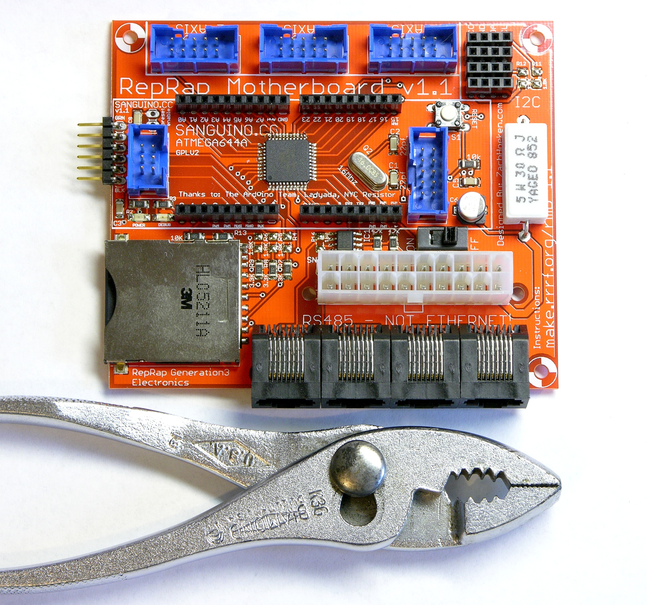
I got mine mostly assembled last week. Like every other piece of electronics in my CupCake kit, my motherboard had missing parts — I got five extra 4.7KΩ resistors instead of the five 1.8KΩ resistors. And unfortunately, that was another part for which I couldn’t find replacements at hand — although I did end up sorting and filing a bunch more SMT components while searching.

After waiting a week for the missing resistors as the solder paste was drying out and getting crusty, I gave up and baked the thing without them. I can hand-solder the 1.8KΩ resistors onto the board when they arrive. And because they’re voltage dividers for 5V → 3.3V level conversion to the mini-SD card and pull-ups for the I2C bus — neither of which is needed for basic operation — I can even run the darn thing without them. I just need to get them on there eventually.

Crusty solder paste bakes just as nicely as gooey solder paste, by the way.

Unlabelled R1 on MakerBot Cupcake motherboard

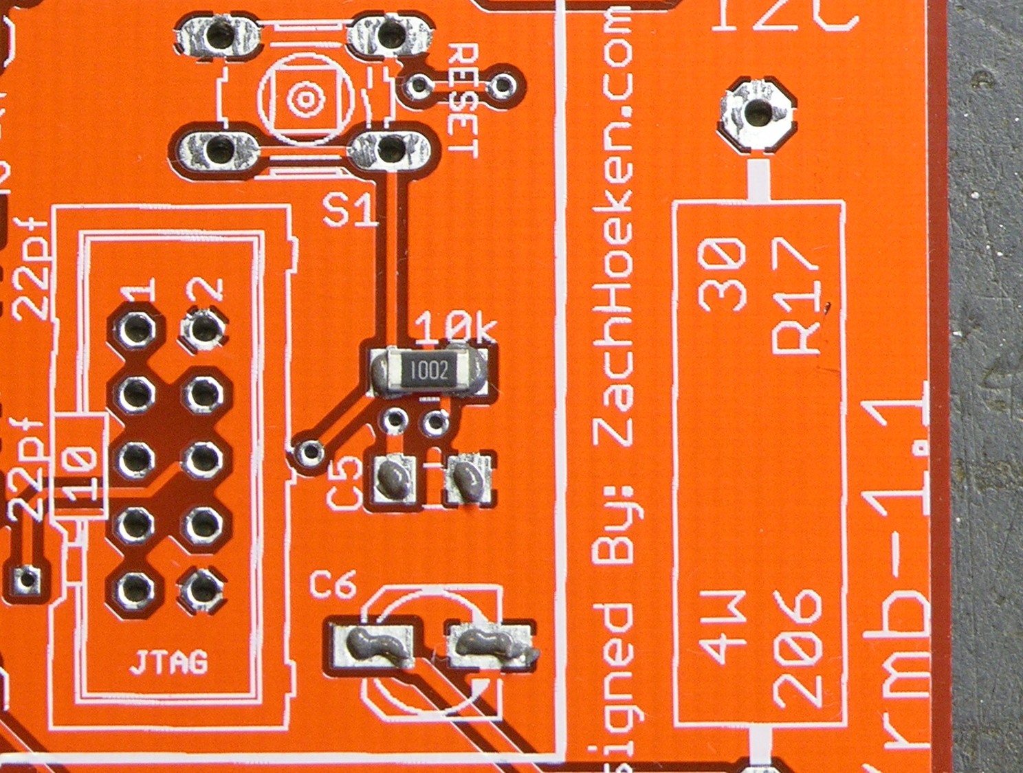
I did spend a while searching for the placement of R1 on the PC board. I eventually found it through a combination of the process of elimination and checking the schematic. As far as I can tell, the name label didn’t make it anywhere onto the silkscreen — can you spot it?

Soldering My Last Two MakerBot CupCake Stepper Boards

Monday, May 18th, 2009

Over the weekend I received the three missing electrolytics, and yesterday I built the other two stepper driver boards.

MakerBot CupCake stepper driver board with flowed, half-melted solder paste

Just one noteworthy item — I meticulously lined solder paste on every IC pad, and then during the “soak” period of reflow (also known as “the time it takes my 500W heater to creep the plate up to 185°C”) the paste all slumped together anyway. (Forgive the poor focus in the picture; my camera’s not very good and that’s the best I could get.)

When the solder paste reflowed, surface tension pulled it all into nice little fillets anyway.

Lesson: Don’t bother tracing every IC pad with solder paste; just run a bead perpendicular to the leads and trust surface tension.

Also, I had one solder bridge during reflow. I took a small screwdriver and poked it between the leads, breaking the surface tension and the bridge. Nice trick, and a quicker (and cleaner!) fix than anything you can do after the solder cools.

Assembling the MakerBot CupCake Extruder

Monday, May 18th, 2009

I’ve been plugging away at the CupCake “Plastruder” in the evenings, and I now have the mechanical assembly mostly finished, pending the arrival of some custom parts.

MakerBot Plastruder plastic extruder

I’m delighted by the clear plexiglas design. And having the mechanical assembly — particularly the extruder — put together really highlights how small this thing is. That’s not a bad thing — for a given build capacity, the smaller the machine is, the better.

(more…)

Soldering the MakerBot CupCake Extruder Controller

Friday, May 8th, 2009

Over the last two evenings, I got my CupCake’s extruder controller assembled.

RepRap extruder controller

I have just a few notes below following up on solder paste, hotplate soldering, and missing and unlabeled parts.

(more…)

Assembling the MakerBot CupCake Stepper Controller (or My First Reflow Solder)

Tuesday, May 5th, 2009

Having got my reflow soldering hotplate assembled Sunday, last night I sat down to build the first stepper controller for my CupCake rapid prototyper. Besides being the first of the CupCake’s stepper controllers, this is also the first thing I’ve ever reflow-soldered, EVAR (although not the first SMT I’ve soldered, as I’ve done that by hand before).

RepRap (MakerBot CupCake) stepper driver on hotplate, assembled and ready to reflow solder paste

There are lots of solder paste and solder reflow tutorials online, and that this ain’t. This is just my observations about parts of the process I hadn’t previously picked up from reading.

(more…)

Makerbot Cupcake Opto Endstops

Friday, May 1st, 2009

I’ve been massively interested in the RepRap project since I first heard of it a few years ago. RepRap — short for replicating rapid-prototyper — is a CNC machine to extrude hot plastic and build up a model additively, like a robot hot-glue gun. It promises to lead the affordable desktop fabrication revolution, printing at home on a sub-$1000 machine what the aviation lab at work printed for me on a $30 000 machine (which itself is already orders of magnitude less expensive than the ones I saw in use when I worked at Cessna Aircraft).

The RepRap can replicate many of its own parts — so once you get one, it’s a matter of feeding it plastic and a few hours (and motors, and circuit boards, and commonly-available hardware) and you can have another one for your friend. It should be pretty viral once it gets going — but getting going is the problem. Even with various “RepStrap” (RepRap bootstrap) designs, the barrier to entry to build my own from scratch was still a bit too high for me — particularly for the heater/extruder nozzle.

So when I saw that Zach “Hoeken” Smith (a member of the RepRap team who’s designed most or all of the current-generation electronics), Bre Pettis (the “talent” on the first Make Magazine videos I remember seeing), and a couple of guys I don’t recognize (sorry, couple of guys!) had teamed up to found MakerBot and were selling the CupCake CNC kit, a complete set of parts to build a RepRap-compatible machine, I was onboard in a heartbeat. The price still feels a bit steep, but the time was right and I got one of 20 presale kits.

It came last week and what with other obligations, I haven’t even had time until last night to start working on it. So I’ll be doing this a slow step at a time; and the first step was assembling the through-hole optical endstop PC boards.

Complete set of Makerbot CupCake opto endstops

The CupCake calls for six endstops — two for each axis — and they use RJ-45 cables for most of the connections, but three-pin headers for the Y axis due to space considerations.

The boards are nicely made; I like it a lot that they’re no larger than they need to be; and I really enjoy the red.

RepRap opto endstop optointerruptor alignment

I have only a couple of cautions for assembling these. First, as noted in the CupCake electronics assembly instructions, the PC board’s optointerruptor footprint is a little off, and it takes some shoving to get the mounting holes aligned. This does matter because these holes are how the board mounts to the chassis, so take the time to get them as close as possible.

RepRap opto endstop RJ-45 jack modification

Second, use a chisel to shave off that spacer tab on the underside of the RJ-45 jacks. If you don’t, they won’t sit flush, and that bothers me.

RepRap opto endstop RJ-45 jack fit with and without modification

Take my word for it, it’s way easier to do this before you start soldering the pins.