Archive for the ‘Repairs’ Category

Modifying a Car USB Adapter to (Finally) Charge My Cell Phone

Saturday, May 28th, 2011

A couple of years ago, I received this automotive USB-connector power adapter as a promotion at a conference. I use it to keep my iPod nano charged in the car, but I’ve noticed it doesn’t charge my Blackberry well. To be precise, it doesn’t charge my Blackberry. In fact, I’ve never been clear whether it even slows the rate of discharge, and sometimes it seems like it speeds it. The Blackberry shows the lightning bolt charging symbol (The charging symbol is a lightning bolt, srsly? Ben Franklin is personally charging my phone?) but nobody’s home.

Note that I don’t blame the vendor whose logo happens to be on it — I’m sure they didn’t manufacture it.

Automotive USB power adapter

After driving two and a half hours a week ago starting with a half charge on my BlackBerry, plugging it in midway through the trip, and arriving to have the BlackBerry finally shut off its radio due to depleted charge; and due to being in the presence of Cort; I decided it was time to see why the adapter couldn’t provide enough charge for the BlackBerry.

Inside the Power Adapter

Sample step-down circuit using RT34063APS DC-DC converter

(more…)

Crisitunity: SSD for the MacBook

Tuesday, April 12th, 2011

A couple of weeks ago, I had my MacBook plugged in and open, but idle for a while, so it parked the hard drive. When I came back and hit a key to wake it, it started saying, “ting wssh wssh wssh.” This is not the kind of language I like my computers to use. The hard drive hasn’t spun up since.

Cort had told me of his impressive performance boosts after upgrading his MacBook to a solid-state drive (SSD) and I’d been interested anyway, so I took advantage of his research and ordered a 115G Other World Computing Mercury Extreme Pro for $230.

MacBook with dead hard drive and new solid state drive

It shipped promptly and I swapped drives that weekend. The rubber shock rails in the MacBook had come loose, so I wasn’t able to slide the old drive out and the new one in through the battery compartment and ended up dismantling the entire MacBook case bottom to make the switch.

I had to reinstall the OS and all of my applications; but fortunately I keep a personal wiki with the download links and installation instructions for all the software I run and instructions to duplicate every configuration change I make to every built-in and third-party application, so reinstallation was a breeze. Also fortunately, I had a synchronized copy of most of my work, so I lost very little data.

The new SSD is just unbelievably fast. Installing apps now happens in the blink of an eye rather than the drag of a progress bar. The boot sequence is still perceptible but the login screen pops up before I’m even quite ready for it. OpenOffice launches so quickly I hardly have time to take a bit of a sandwich, much less go make one.

Hammond XB-2 Drawbar Decoding Diagnosis and Repair

Saturday, March 5th, 2011

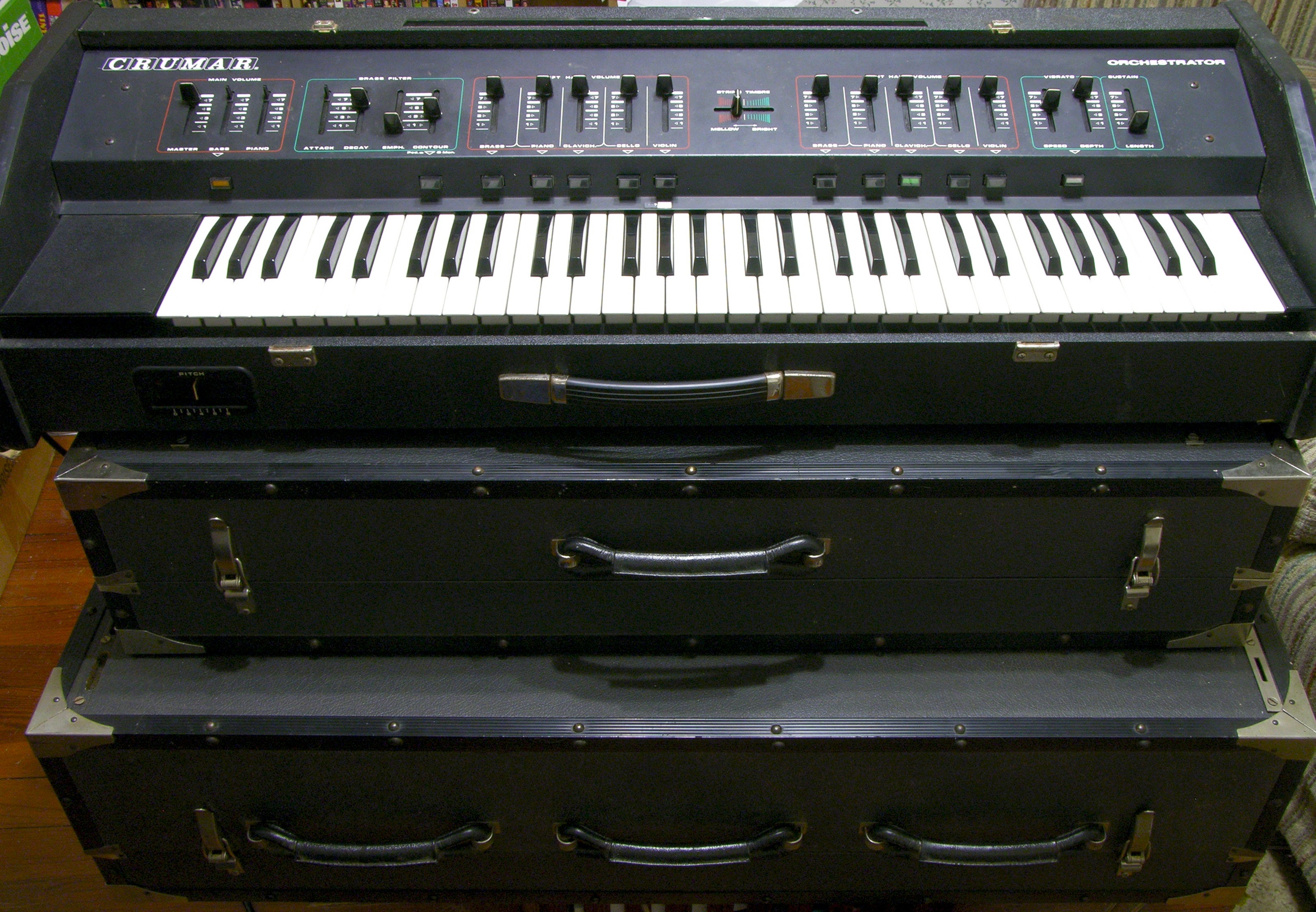
A couple of weekends ago I took the two XB-2s that I had (at the time) over to Ron’s shop to have a little more room to spread out and test things. Like real Hammond tonewheel organs, the XB-2 has “drawbars” that represent different harmonics (or subharmonics) of the fundamental frequency of each key being pressed; you draw out the bars to mix different amounts of the different harmonics to get the timbre you want. This is additive synthesis at its most visceral.

Hammond XB-2 drawbars

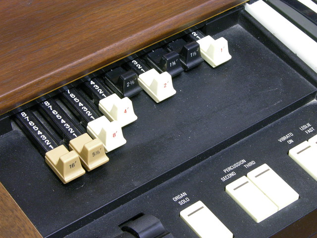
On the XB-2, the drawbar positions (either live or recalled from memory) are displayed on an LCD below the manual (keyboard). In live mode, the bar graphs move in and out in synchrony with the physical drawbars.

Hammond XB-2 drawbar display

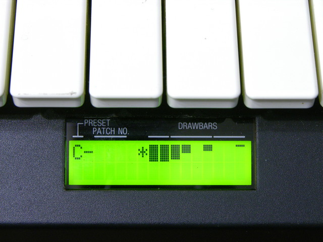
On one of the two XB-2s, the LCD bar graphs didn’t match the drawbars — a couple of drawbars appeared to work properly, but some didn’t work at all and others moved multiple bar graphs on the display. Since the drawbar decoding is a relatively independent section of the organ, it seemed like an easy repair to tackle first.

Hammond XB-2 drawbar schematic

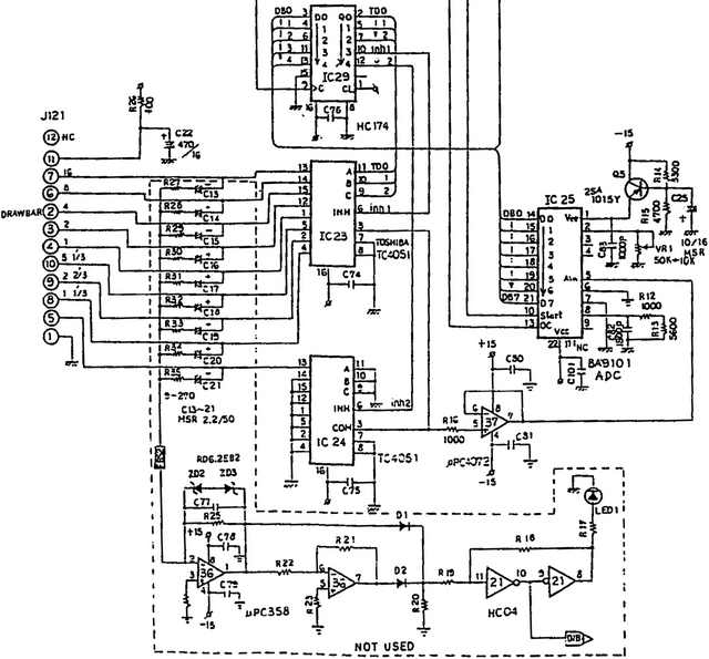
The drawbar’s wiring harness plugs into the main board on J121, at the left of this section from the service manual. Each drawbar is a detented slide potentiometer, so variable voltages are arriving on J121. The section enclosed in the dotted line and marked not used truly isn’t populated on the circuit board, so I omit it from discussion.

The nine analog drawbar voltages are delivered to IC23 and IC24 (TC4051 analog multiplexers). The multiplexers receive their enable and select signals from the output of IC29 (74HC174 hex D flip-flop) which is latching signals previously delivered from the system data bus. (In other words, the 74HC174 is the drawbar select register; its own address is decoded elsewhere in the schematic.)

The chosen (enabled) TC4051 analog mux selects which input to pass to its output on pin 3, which is then op-amp buffered and delivered to the input pin of IC25 (BA9101 analog-digital converter). When selected (more system address bus decoding), the ADC writes the digital value of the drawbar’s position onto the system data bus.

Side note: For the drawbars only having nine detents (0-8), IC25 sure delivers a lot of bits of ADC resolution to the data bus.

I put a scope on IC23 (analog mux)’s output pin and I was able to view on the screen the time-division multiplexing of the drawbar positions (analog voltages) onto the single line going to the ADC. It mostly matched what I saw on the LCD, although there were some quirks with a few of the drawbar time divisions appearing narrower than others. Ignoring the odd widths and recording which drawbar occupied which time division:

Drawbar Time-Division Multiplexing Behavior
Drawbar 16 8 4 2 1 5 1/3 2 2/3 1 1/3 1 3/5
IC23 Pin 13 14 15 12 1 5 2 4 (IC24)
IC23 Input Good MB 0
(000)
1
(001)
2
(010)
3
(011)
4
(100)
5
(101)
6
(110)
7
(111)
(IC24)
Bad MB 0
(000)
1
(001)
7
(111)
7
(111)
0
(000)
1
(001)
7
(111)
7
(111)
(IC24)

On the working XB-2 motherboard, the drawbars were selected and sampled in numerical order. On the broken motherboard, as you can see, any time the analog mux’s select bit A1 was enabled, the mux behaved as though bits A2 and A0 were enabled as well. Further, select bit A2 didn’t work on command as it should when drawbars 4-7 should have been chosen.

4051 Address Pins
Name C B A
Function A2 A1 A0
Pin 9 10 11

It could be a bad 4051 mux; but as we had already replaced a leaky electrolytic capacitor in the neighborhood, it seemed worth another look at the circuit board first. The 4051′s select lines are on pins 9-11, and what’s this?!

Hammond XB-2 main board, drawbar section

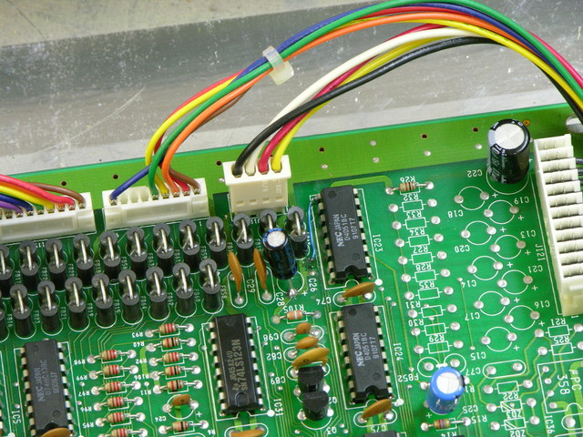
I became suspicious of a damaged via on a trace that turned out to connect to pin 9 (A2). A continuity test showed that the via — even its top side — was no longer connected to IC23; the trace up to the via had been eaten away by the leaking capacitor. The via — even its top side — did have continuity to its next stop on the PCB, so the via itself was intact.

Ron heated the solder that had wicked into the via during reflow, inserted a piece of wire-wrap wire, and soldered the other end directly to IC23 pin 9. The drawbars now work perfectly. I suspect the floating select input on the CMOS mux was picking up enough signal from the PCB trace inductively coupled to its neighbor to trigger.

My hypothesis is that the previous owner put the keyboard away because of larger (ROM / CPU / Muse) problems; the capacitor leaked and damaged the drawbar multiplexer trace while it was sitting idle; and the owner never even knew about the drawbar problem. At any rate, it was easily fixed and the troubleshooting was a rewarding mental exercise.

Hammond XB-2 ROMs?

Saturday, February 12th, 2011

I have two secondhand Hammond XB-2 Hammond clones (c’mon, even if it had made by Hammond proper before being bought by Suzuki, a solid-state, digital audio synthesis keyboard is still a clone) which both appear to have bit rot in their firmware EPROMs, apparently a common problem with these keyboards.

I’d be extremely grateful for pointers to where I could get new EPROMs or download images to burn myself, or to another XB-2 owner willing to read out their EPROMs to assist. Heck, I’ll burn you another copy so you have a fresher set when yours bit-rot.

They’re IC16 and IC17 and they’re 27256es.

Fixing Jeremy’s Ford Mach 460 Bass Amplifier

Saturday, October 2nd, 2010

Sometimes you get lucky.

Ford Mach 460 bass amplifier

My friend Jeremy has a 1995 Mustang that had the factory premium sound system in it when he bought the car used. The CD player was broken and he had the head unit replaced within a couple of weeks of owning the car. He later added a subwoofer.

I’ve always thought the stereo lacked clarity in the bass, and the head unit and EQ have had some quirks. Recently Jeremy pulled the head unit and found all sorts of interesting techniques used by the aftermarket installer that will be the subject of a later monologue … but one of the things we discovered is that the amplifier for the door woofers wasn’t working at all. Swapping it with the amp for the rear deck woofers caused them to go silent and the (shot) door woofers to work again (after resoldering their cut cables).

Turned out to be a delightfully easy fix.

(more…)

Repairing a Crumar T1 Organ Swell Pedal

Friday, August 6th, 2010

Crumar stack

Both my Crumar T1 and T2 “portable” organs (the lower two cases in the stack) came to me without swell (volume) pedals. Each has a rotary potentiometer on its control panel for master volume, but I really want to be able to change the volume dynamically while playing. I’ve been using a Dunlop volume pedal (built into a rocker case identical to the CryBaby wah) on the organ’s output; but (at least when used with the organ) all of the pedal’s action is in about the lower quarter of its physical range, so it’s very finicky to use.

Crumar T1 organ swell pedal

I recently bought this original T1 swell pedal on eBay, listed as untested / project. That usually means tested / didn’t work / can get more money if I don’t admit that I already know it doesn’t work; but I figured I could fix whatever was wrong with it. And I have.

Crumar T1 organ swell pedal photoresistor enclosure

(more…)

Repairing a Bad Horsie 2 Wah Pedal with Power Damage

Wednesday, July 7th, 2010

Bad Horsie 2 wah pedal

I recently ran across on Craigslist a

Bad horsie 2 that was plugged into the wrong power supply and messed up, and needs some minor electronic work.

I was intrigued by the challenge (I’m such a sucker for broken things, dang it) and bought it. When the seller and I exchanged the pedal for my cash, he remarked that he read on a forum that it probably just needed a resistor changed, and that if I were handy with a soldering gun I could probably do it myself.

Uh huh. Resistor.

Let’s dig in.

Bad Horsie 2 wah pedal circuit board

The circuit board has a hole in the top for a foam battery “cage” attached to the enclosure, something clever that I haven’t seen before. And it had no obviously damaged components.

(more…)

Installing Batteries in a Liebert GXT2-2000RT120 UPS

Sunday, June 27th, 2010

A while back, I bought a secondhand Liebert GXT2-2000RT120 uninterruptible power supply (UPS) on eBay. The GXT2 is a series of online UPSes, meaning that the output power always comes from the inverters off the battery bank; it doesn’t switch from utility power to battery power like an offline UPS. Besides eliminating any possible switchover glitches, online UPSes always deliver conditioned power at a constant voltage. The 2000RT120 is a 2000VA unit with 120V output — large enough to power all my servers for a good little while.

Liebert GXT2-2000RT120 UPS with battery cage disassembled

The batteries were due for replacement and the seller removed them to save on shipping costs. I got a UPS with a set of wires and no instructions on how to connect them.

Liebert GXT2-2000RT120 UPS battery wiring

Also one of the wires was compromised … but since it appears to be a ground wire, I figured no big deal if it shorts out against the cage. KIDDING!

Yesterday I figured out the wiring, installed batteries, and got the UPS set up in my server rack.

(more…)

Repairing a Patch Cord

Monday, May 31st, 2010

Recently a couple of pieces of audio processing equipment I’ve bought used have had bad left channels. After recognizing the pattern, I finally thought to swap out the patch cord I had left plugged into the “test” channel on my keyboard mixer, and voila! Left channels fixed.

Audio patch cord, disassembled

I’ve always been curious about the construction quality of commercial patch cords — just how good are the connections buried under those lovely molded jackets and strain reliefs?

Naturally, the faulty end was the last one I disassembled. (Logic joke!)

(more…)

Replacement Headphone Cables?

Thursday, May 20th, 2010

I have a whole box of what I believe to be moderate- to high-quality over-the-ear headphones with worn-out, shredded cords.

Anyone know a source for replacement headphone cables, preferably straight (not coiled) with 1/4″ plugs, and absolutely with supple cable and alreadying Y-ing out to both ears? 6′ cable would be okay and 10′ would be fantastic.