MakerBot CupCake Heated Extrusion Bed Part 1: McWire PCB Heater

March 9th, 2010 by Keith Neufeld

Over the holiday break, I had written about using a hairdryer to heat my CupCake build chamber.

On January 11, 2010, Tom McGuire wrote:

Hey Keith, I haven’t caught up with your blog for some time. Looks like you got a lot done in the last couple weeks. It’s good to see you’re getting results from your CupCake.

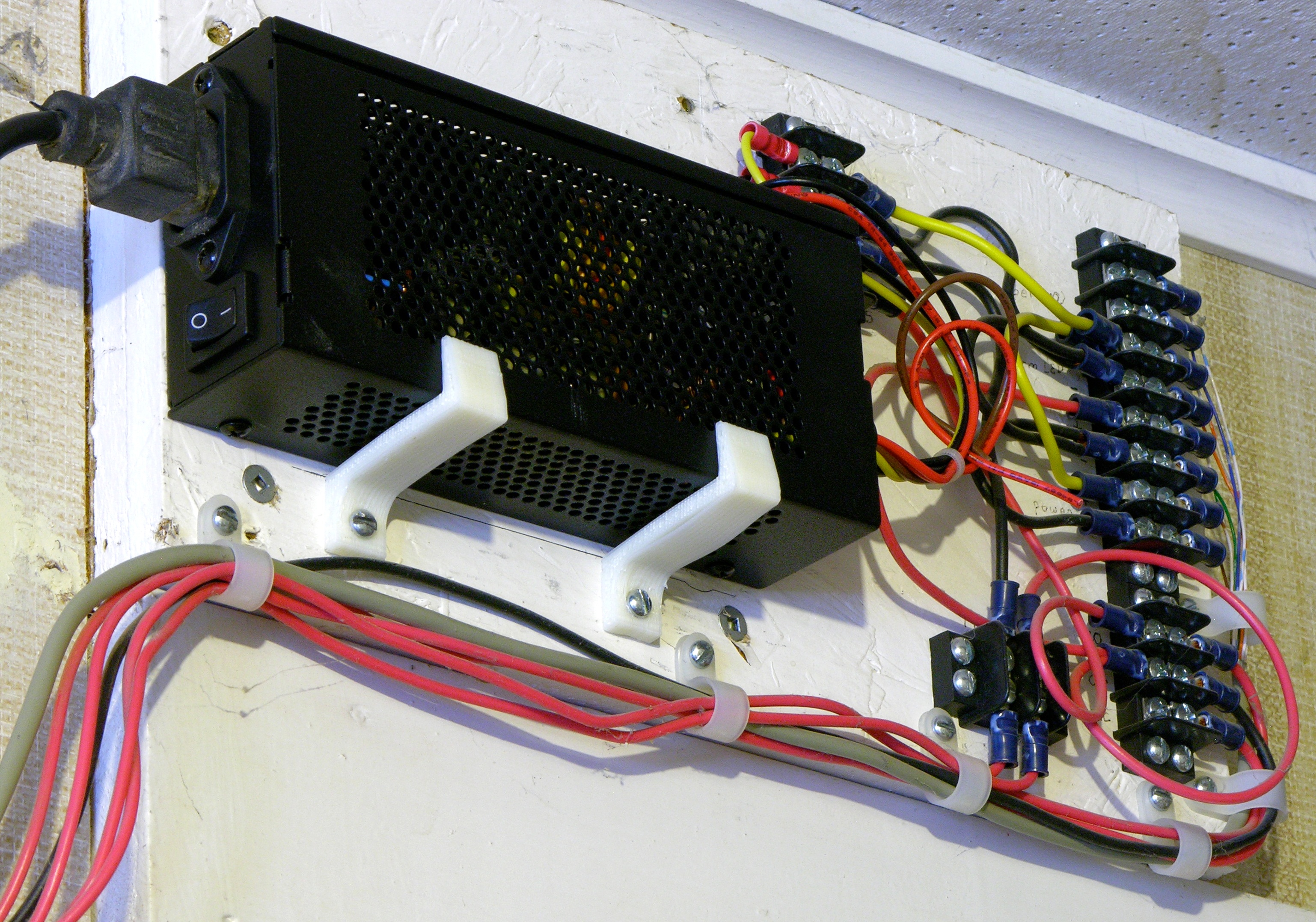
Can I help you with a hot plate? I could make you a thin aluminum plate about 4″ square that gets up to 200°C. I guess you would need it to be insulated on the bottom to keep from burning your stage. Do you have a low voltage with lots of current available, say 12V @ 10A or may be 5V @ 20A. What do you think?

What did I think??? I thought it sounded great! The heated chamber was helping my prints, but I was still getting some warp. I knew a heated platform was the way to go and it had been my goal all along.

Spiral PCB heater

We started discussing the way other folks were making their heated platforms and Tom went on to say:

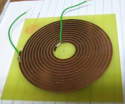
Oh 100°C would be no problem for PC board material. I was thinking at first to place a bunch of low ohm surface mount resistors around on a 4″ square PC board but then I remember we did this other project that was supposed to be in inductive coil for an induction heating system. It turned out to be more of a heater coil itself. I could do something like this but in a square pattern and leave openings for your screws and magnets.

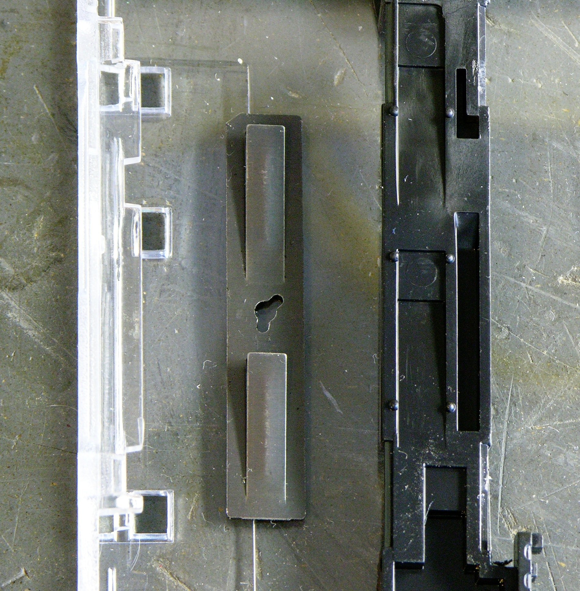
Because I wasn’t sure yet whether the heater PCB would mount fairly directly to the Y stage (and thus need holes for screws and magnets) or be raised above it (far enough that it wouldn’t need holes), I pointed Tom at the CupCake CAD files on Thingiverse.

PCB heater board layout

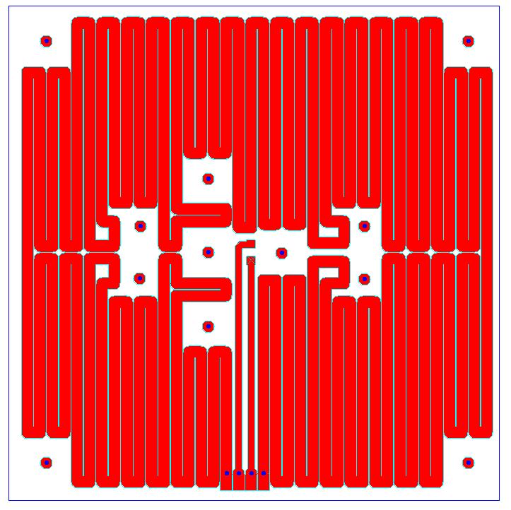
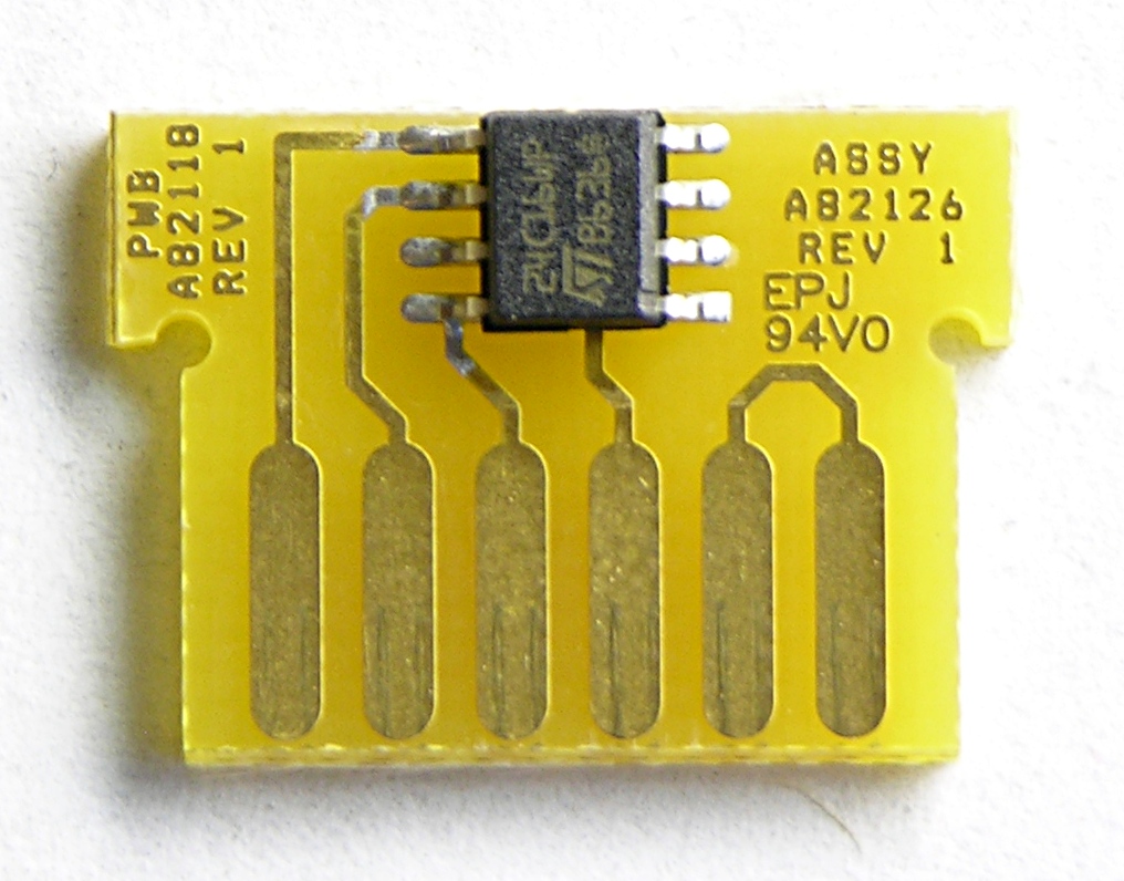
He downloaded the DXF for the original build platform to get the hole size and spacing, then laid out this heater PCB with traces fitting around all the necessary openings.

PCB heater with SMT thermistor

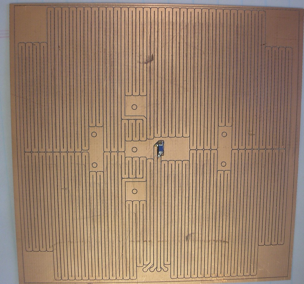
Then he showed up for lunch with a milled heater PCB that ended up measuring 4Ω resistance (an extremely convenient value) and with an SMT thermistor already soldered in the middle.

Relocating the MakerBot CupCake Extruder Controller

March 8th, 2010 by Keith Neufeld

I’ve been dissatisfied with having the CupCake’s extruder controller attached to the front of the extruder. The PC board (being opaque) blocked the view of the feed mechanism. As much trouble as I have with filament feed, it’s pretty important for me to be able to keep an eye on it.

Actually, as many times as I’ve had to disassemble the feeder (replace broken idler pulley, reglue idler pulley, remove broken feed pulley flange, replace broken plastic?, etc.), I also got tired of having to remove the PCB every time.

And <whine>the patch cord didn’t route nicely from the side of the machine facing forward to the top of the machine facing up.</whine>

MakerBot CupCake with extruder controller moved to main body side panel

I’d previously mounted the extruder PCB up on the highest two screws of the extruder housing, placing it above the feeder face instead of covering it, but that was pretty fragile and I was constantly worrying about bumping it and snapping it off. This weekend I moved the extruder controller to its new permanent home on the right side of the CupCake in the empty space above the motherboard. It fits nicely and shares a mounting screw with the upper Z-axis endstop.

MakerBot CupCake with extruder controller moved to main body side panel

It does block access to the SD card slot, but I don’t use SD cards anyway. Even if I do someday, I think I’m most likely to put a card in it once and leave it there for doing prints without a host computer connected. Now that I’ve eliminated printing stalls and blobs, I don’t have a lot of reason to try uploading designs to a card every time before printing, nor save designs to a card from the host to then install into the machine.

When I have time, I’ll make a shorter (4″?) patch cord to jumper from the motherboard to the extruder controller without all the excess I currently have coiled up.

Cable Lacing

MakerBot CupCake with extruder controller moved to main body side panel

I also got to try my hand at cable lacing, something I’ve long admired in old TVs and vacuum tube organs. I don’t know that it’s the right look for a modern rapid prototyping machine, but the waxed string cost only a pittance and it doesn’t have to be the permanent solution.

The cable clips I had on hand were too big to anchor the mobile end to the extruder properly, but they do help guide the cable until I can buy smaller clips. Initially I had thought I’d need to enclose a piano wire in the cable bundle to help it maintain its arch, but it’s flexing very nicely without additional support.

Extruder Wire Gauge and Current

I’ve been concerned about the ability to deliver enough power to the extruder controller over the ethernet patch cord, especially when people are running heated build platforms off it too. I realized after the fact that I should have checked the wire gauge I was using before extending the heater wires out the top of the machine, but let’s check it now.

Powerstream.com provides a wire gauge and current table and calculator. For the 24-gauge wire I used, they list the maximum amps for chassis wiring as 3.5A, which is a comfortable margin over my actual current of 12V / 6Ω = 2A, so I’m safe.

Toward the bottom of the page they have a load calculator. Entering 24-gauge copper, 12VDC, 1.5′ one-way length, and 2A, they show a round trip .158V (1.32%) drop in the wire and 11.842V delivered to the nichrome heater. Not too bad.

While we’re here anyway, let’s do the math for running both the nozzle and platform heaters from the extrusion controller in its original configuration. The interface uses three wires of the (almost certainly) 24-gauge patch cord for each of 12V and GND, so that’s equivalent to just over a single 20-gauge wire.

The nozzle heater was 2A and I see people talking about 4-6Ω platform resistance for another approximately 3A. The chart says 20 gauge is good for 11A for chassis wiring, which is a comfortable margin. The calculator shows a .314V drop over the 3′ patch cord, still delivering 11.7V to the extruder controller. Quite acceptable and nowhere near as bad as I feared.

Making Mini Extension Cords / Testing New Solder and Heatshrink Techniques

March 7th, 2010 by Keith Neufeld

When you cut up an extension cord for speaker cable (I’m no golden-eared audiophile; I just need some copper to get a few hundred watts from place to place), save the ends to reassemble into mini extension cords. They’re perfect for plugging wall warts into receps and power strips without making adjacent receps unusable too.

I’ve spliced a lot of different kinds of cables — sometimes repairs for friends, sometimes Frankensteining things together for a project — and I’ve always been dissatisfied with the aesthetics when I’m done. Covering the joint in heatshrink hides the ugly splices from direct view, but the heatshrink tapers where it falls off the edge of the cable’s jackets and has unsightly bumps covering the solder joints.

This weekend I tried out a couple of ideas for achieving a smoother splice. The basic method was sound; and although the results aren’t yet what I hope to accomplish, I think they’re leading in the right direction.

Extension cord with jacket ends cut for splicing

My first idea was based on a woodworking scarf joint — a fancy term for cutting ends on a diagonal to make a joint less visible. I sliced each jacket lengthwise about an inch and a half from the cut end, then attempted to cut the peeled jackets into smooth diagonals.

Offset solder joints in a cable splice

I tied the jacket pieces out of the way with velcro, preloaded the wires with heatshrink to cover the splices, and soldered the individual wires together. Note that the individual joints are all offset so that even if the heatshrink were to fail or be abraded, the exposed joints still couldn’t come into contact and short out.

Cable splice with jacket pieces not quite fitting

It turns out that eyeballing the mating jacket shapes before putting the cable back together is a bad idea (or at least that I’m not very good at it). I left a fair bit of gap, uh, everywhere — if I were to try it again, I’d wait to cut the scarf (scarves?) until the reassembly stage, at which point I could do a better job of mating them.

Note that the way the jackets flare out where they come from the unaltered cables into the joint is due to heat while heatshrinking the individual wires, not due to the bulk of the splice area.

Spliced cable with lumpy heatshrink

The result is arguably smoother than my previous methods; but because the lumps don’t logically derive from the splices inside, I actually find it more aesthetically displeasing.

Spliced cable with jacket rewrapped over joint

On the second cord I spliced, I slit the left jacket but didn’t shape the split end and I cut the right jacket completely off the cable. After soldering and heatshrinking the wires, I wrapped the left jacket back around the joint, covering it pretty cleanly. The gap where the two ends’ jackets meet is quite evident, but this shows that rewrapping the wires in the cables’ own jacket is a considerable improvement over just heatshrinking the joint.

Two spliced extension cords

Two short cords, ready to use with wall warts.

For next time, I’m most interested in retrying the scarf joint and cutting the two jackets to mate after finishing splice. I think it offers a good chance of minimizing the gap at the end of each jacket, and I think the long diagonal gap under the heatshrink could be nearly invisible with a little care.

Obligatory cautions: Electricity is dangerous. Splicing cords is a bad idea. Don’t burn your house down. Make sure extension cords are unplugged before soldering. Do not taunt mini extension cords.

Folder Structure Standardization and Unison for File Synchronization

February 16th, 2010 by Keith Neufeld

We’re smart, electronics- and computer-savvy folks, right? So why is it that when I’m trying to figure out which of my computers a particular EAGLE project is on, I have to envision where I was sitting:

  • couch or kitchen == iBook or MacBook
  • home office == workstation
  • work is unlikely but == work computer

and about how long ago it was:

  • more than a year == iBook
  • less == MacBook

? Shouldn’t all of my files be available to me wherever I am? Why should I have to guess and look around and always have them in the wrong place?

Oh, sure, when I upgraded from the iBook to the MacBook, I could have used Migration Assistant to copy everything over; but it seemed like a great time to declutter, organize, and start fresh. And it was, until I didn’t get around to the organizing part and needed EAGLE files I hadn’t brought over yet. Like, now.

I’ve been home sick from work today yesterday and today, and during the parts that I was awake I got files synced across my different platforms. I haven’t been playing sick to get a chance to sync up my computers — whatever I have is making me sniffle, speak about an octave lower than normal, drink gallons of orange juice, and listen to Madonna CDs. You don’t want what I have, and neither do the people I work with.

Unison Background

For a long time, I’ve been intending to install Unison for syncing my electronics project files (entire hierarchies, actually) across the different computers I use. Now I’ve actually done it.

Read the rest of this entry »

Need a Name for a New Site Feature

January 31st, 2010 by Keith Neufeld

I have a lot of old electronics equipment that I thought I wanted to save at the time I got it but is of no particular use to me. I’d love to find new homes for it; some I’d give away for the cost of shipping and some I’d take offers.

I’m thinking about setting up a new area on my web server to post pictures of and information about things I have available, and I’d like a good name for it so I can link it as http://something.neufeld.newton.ks.us/ and http://www.neufeld.newton.ks.us/something/, but I don’t know what that name should be.

I’d love to call it http://free.neufeld.newton.ks.us/, but it won’t all be quite free. I don’t want to call it “store” because I’m hoping to turn a couple of my projects into kits soon and I’d like to reserve that name for information about the kits.

The best I’ve come up with so far is “fleamarket,” and I’m not wild about that.

Suggestions welcome. Free junk for the “winner.” :-)

Electronic Circuit in Panduit Labelmaker Cartridge

January 18th, 2010 by Keith Neufeld

Panduit labelmaker cartridge

I don’t remember exactly where at work I found this empty labelmaker cartridge, but this view isn’t what caught my attention.

Panduit labelmaker cartridge, PC board visible

Here’s what piqued my interest — a tiny PC board inside the cartridge.

Panduit labelmaker cartridge, edge view

I’m aware of inkjet printer manufacturers adding PC boards to their ink cartridges and then perverting the intent of the Digital Millennium Copyright Act‘s anti-circumvention measures to prohibit third parties from producing compatible ink refills. Would Panduit stoop to such depths? I had to know. What was that chip???

PC board from Panduit labelmaker cartridge

Easily answered — the sole IC on the PC board looks like a harmless 24C16 I2C serial EEPROM. It probably informs the labelmaker of the label size and shape. No big deal!

And now I have another 24C16 in my parts bin.

Blu-ray Theft-Prevention Case and Hard Drive Magnets

January 18th, 2010 by Keith Neufeld

I don’t have a Blu-ray player yet, but I’m doing the same thing I did when I switched from VHS to DVD — buying in the new media when I think prices are reasonable, then buying a player after I have enough media to justify it.

Blu-ray movie in theft-prevention case

Here’s one of my first such purchases, with the cover image obfuscated to protect the copyright-holder’s interest in their artwork. (Note that this is one of my highly-favored movies and I already have two different DVD editions. Wouldn’t want anyone to think this was the first copy I was buying.)

You can see that Target somehow neglected to remove my purchase from their theft-prevention case. I don’t know how that happened, but I do have the receipt. I could easily have ruined the case (bandsaw) to remove my movie, but that would have been so inelegant.

Please use this information only for good.

Blu-ray movie case theft-prevention mechanism

The case hinged open at the bottom of the movie and was held closed by a sliding black plastic strip at the top, shown disassembled here. The strip locks the case shut and in turn is prevented from sliding to the open position by two ratcheting leaves protruding from a metal strip that’s pinned to the case.

Examining the case, I couldn’t find holes where pins could enter to withdraw the leaves, so I guessed magnets. The metal strip did seem to be attracted to magnets, but the ones I had on hand weren’t strong enough to pull the leaves. I knew I had to find a sacrificial hard drive to take apart.

Seagate Barracuda hard drive with PC boards torn away

I got this drive that had been removed from a decommissioned PC at work and, um, “read-protected” by one of our technicians. (I’m afraid it may not have been zeroed first, and I’m hanging onto the platters until I can figure out whether I have something strong enough to degauss them.)

Magnets on Blu-ray movie case

The permanent magnets from the head-positioning assembly retract the leaf springs quite nicely, allowing me to slide the locking strip and open the case. Of course I actually held one magnet on each spring to unlock it, but I wasn’t able to keep them that way for the photo.

Voila! One open case, and one more Blu-Ray movie for Keith.

“New” Crumar T2 Organ Part 2: Easy Fixes and Investigation

January 4th, 2010 by Keith Neufeld

As mentioned previously, I recently bought a Crumar T2 organ manufactured in 1978 and started ascertaining its condition. Here’s what I’ve been able to fix so far and what I’ve been able to determine about the parts I haven’t yet fixed.

Crackly Volume Knobs and Stuck Master Tuning Potentiometer

Several of the volume knobs were pretty crackly.

Crumar T2 organ with control panel lifted

Most Crumar keyboards are wonderful to service because of how easy it is to get inside. After removing a few screws, the top panel lifts back on its rear hinge, without even having to take the knobs off all the controls.

Read the rest of this entry »

Reconing an Eminence JAY7010 Subwoofer Driver

January 3rd, 2010 by Keith Neufeld

Earlier this year I bought some PA speakers at auction. The auction company was cagey enough to list them all as “untested / condition unknown,” but I suspect they had a pretty good idea of the condition.

Eminence JAY7010 18-inch driver on chair

I ended up with a Yamaha SW1181VS 18″ 500W subwoofer, a Yamaha Yamaha CW218V dual 18″ 1220W subwoofer, and a spare Eminence JAY7010/7011 18″ driver. All four of the Eminence drivers were nonfunctional — some dead shorts, some open. This was a bit disappointing.

My four drivers all look the same, but are labeled JAY7010, J7010, and J7011. From what I can tell, Eminence OEMed these drivers for Yamaha and they don’t seem to be available for direct sale. I found a speakerplans.com forum post with specs sent by Yamaha listing the drivers as 600W. I also found a Google listing summarizing an expired eBay auction claiming that these are the same as the Eminence Sigma Pro, which is a 650W driver widely available at around $160.

For the prices I paid for the Yamaha speakers, new drivers at $160 each would go a long ways toward the cost of entire new speakers — the CW218V (dual) is available from Musician’s Friend for a little over $700 with free shipping.

I had never before heard of reconing drivers, but quickly ran across it in my Google searches for J(AY)7010/11s. The idea is that the basket and permanent magnet are still good, that a new voice coil and cone cost less than the whole thing, and that you can replace them yourself at home with a little time and care. Eminence offers recone kits for all their consumer drivers, but recone kits for custom and OEM drivers are available only to the OEM customer.

Although soundspeakerrepair.com has a great instructional video on the reconing process, I ended up getting my kit from reconekits.com for $69.23 + $13.95 USPS Priority Mail flat rate. Over the holiday break, I took the time to install the kit, and the results have been fantastic.

The Kit

Speaker reconing kit instructions: contents

Speaker reconing kit in box

Read the rest of this entry »

New Power Supply for (Home) Electric Lock System

December 26th, 2009 by Keith Neufeld

For over a decade, my (self-installed) electric lock system from the garage to the utility room has been running on a used PC power supply. The cooling fan had stopped turning, the power supply was discarded, I peeled up the foil sticker over the bearing and added oil, and the fan worked again for another five years until its next service appointment.

This fall, the power supply stopped altogether; and that became the impetus to install a smaller, silent (passively-cooled), non-PC power supply.

Electric lock wiring panel and power supply

Power supply via Extreme Recycling of Topeka; mounting brackets courtesy of MakerBot CupCake. The slight delamination on the right bracket is because I’m still tweaking the best extrusion width over height and the perimeter was too sparse.