Treasures from Slim

December 11th, 2007 by Keith Neufeld

An ice storm was predicted for today; and in anticipation, the university shut down. Even faculty and staff don’t go in for a full shutdown.

Icy trees on my street in North Newton

Temperatures must have been quite a bit higher than expected; because although there’s some ice on trees, all the freezing rain that hit the ground stayed wet and is draining away.

Icy tree looming over garage

So here I am at home, waiting for more limbs from my neighbors’ tree to fall on my garage, and catching up on some electronics.

Another Weekend of Cleanup

Cort and I went to Pittsburg this past weekend to help Maeve clean up more of Slim’s stuff. The focus this time turned out to be books, but we each plundered other areas as well.

Ohmite resistor cases

I adore these vintage resistor storage cases. The drawers are about 1/2″ high — you don’t need much more than that to store resistors — and they’re totally dreamy. (Um, yup, I’m a geek. :-) )

Engler Hour Meter

Cort and I found this on a shelf in Slim’s garage:

Engler hour meter, angle view

It’s an Engler Instrument Company hour meter model 10N, and I think it’s absolutely gorgeous.

Engler hour meter, face

It wants to be built into a rich walnut case for something. (I’m not an active steampunker, but I definitely admire real and faux antique gear with wood and brass and glass and gleaming chrome and flicking needles with paper scales behind them.)

Engler hour meter, back

Give it 110VAC and it counts hours. The case is riveted shut, so there’s no resetting it. Still, it wouldn’t be that hard to run it long enough to reset — only about 35 months. (I’m going to need a good reason to do that, though . . .)

Slim’s Microcontroller Development Drawer

Slim's microcontroller development drawer

I’m not sure which cabinet this came from, but Maeve had taken a whole drawer full of Slim’s microcomputer and microcontroller development gear out to the garage. Cort and I picked through it, boxed it all up, and brought it home.

Some of the detail that follows is as much an inventory for Cort and me so we know what we have and where it’s packed, as it is intended to be of general interest.

PIC sticks

Lots and lots of microcontrollers and related chips: Two sticks of TL064 op-amps, three sticks of PIC16C55s, three of PIC16C56es, two of PIC16C57s and two UV EPROMable chips, two sticks of PIC16C71s, a stick of ISD 4004-16MP 16-minute audio recording chips, a stick of ADCs, a bunch of miscellaneous Mozer Digitalker chips, an XC68HC705K15, and a couple of MC68HC811E2INs.

Circuit Cellar RTC52 and RTCIO kits

Circuit Cellar RTC52 and RTCIO kits, unassembled. I was never a subscriber, but these appear to have been the foundation of many Circuit Cellar control and automation projects; see for example this touch-tone remote-controllable home automation system from 1991.

PICBASIC development kit

A PICBASIC development kit.

Microcontroller development boards

Various microcontroller development boards, at least two of each, and heavily biased toward Motorola.

M68HC705KICS development board

An M68HC705KICS programming board, adorably fitted in a box with cutouts for the power leads and ribbon cable, so it never has to leave its nest.

SWTPC boards

A RAM board and two MP-09A CPU boards from a Southwest Technical Products Corporation 6800/6809 computer, circa 1978. I would really like to find a good home for these with a SWTPC collector. I think there’s a related chassis in storage as well, which I’ll dig out next time.

LCD screens

Couple of LCD screens in “widescreen” format. :-)

Speech synthesizer board

A very funky, battery-powered speed synthesizer board. Cort said Slim picked this up somewhere (probably at the Dayton Hamvention) and the two of them (particularly Cort) poked at it for a long time figuring it out. They were able to get it to make noise, and it has both recorded phrases and a phoneme generator, but they never found any documentation about the dictionary and weren’t willing to spend the time to catalog it by trying every address. Cort also said it draws half an amp.

Huge pushbutton switch

And a very large, datacenter-style pushbutton switch. Sweet!

Garrett’s Wife’s PC Stopped Working

December 6th, 2007 by Keith Neufeld

Damaged CPU

LED Puck Design Questions

December 1st, 2007 by Keith Neufeld

Cost: Realistically, I see this thing climbing into the $15-30 range for materials. That’s more than I’d pay to buy a puck from ThinkGeek, but not more than I’d pay to construct one myself that I helped design. Anyone else?

Battery: Seems like we’d get a lot better power density (translating to smaller size and longer runtimes) if we used an RC-style LiPo battery, I’m thinking about the size of a matchbook or so. This’ll be more expensive; but I’m concerned that fitting in 2-3 AAA or AA cells will make the puck bulky that it’s not cool anymore. How do you feel about having to buy a special battery for it?

Charge circuit: I can find a charge-control chip and use the datasheet’s sample implementation as well as the next guy; but that’s really just a starting point, and I understand there are often subtleties involved in getting the best real-world performance. Does anyone have a lot of charging circuit design experience, or know someone who does, who’d be willing to design that portion and contribute it to an open-source hardware, community-developed project? We might want to look at LadyAda’s WaveBubble or the Chumby design for reference.

Voltage-boost circuit: Depending on what battery, microcontroller, and LEDs are used, we may need to boost the battery voltage. Same questions as on the charge circuit.

Surface-mount components: I don’t think there’s room to use through-hole technology. I’m envisioning at least the microcontroller, LED driver, and optional real-time clock chips being SMT. LEDs need to be through-hole, in my opinion, both for rated brightness and so they can be aimed slightly away from the center for better light dispersion. Will a few SMT components be enough to keep anyone from building this who would otherwise be interested?

Enclosure: My first thought was pouring this thing in resin, but I’d really like to be able to take it apart and service / enhance it. I’m now leaning toward a two-piece milled enclosure (probably lexan) that would sandwich the PCB edges in rubber for shock control and hold together with recessed screws underneath. Add an appropriate O-ring and the whole thing could probably be made watertight — which in my book counts as another feature. :-) Thoughts?

What Features Do You Want in an LED Puck?

November 28th, 2007 by Keith Neufeld

Underworld: Evolution features hockey-puck-sized bombs that click open, disperse visible vapor, and then blow up real good.

Why should the destructive guys have all the fun? I’m inspired to make design an LED puck, for special-purpose lighting. Power goes out and you need to enough light to shut down the UPS-protected computers? LED puck. Camping and you need to find your gear inside your tent? Puck. Kidnapped and locked inside a trunk? Puck. (Also “cocktail party,” but that’s a different movie.) It’s dark and you want to show off a cool gizmo? Puck!

My friend Joel can help me cast it in clear resin to protect the LEDs — but casting it in resin makes it harder to tweak later, so I’d like to get the feature set right on the first try.

What would make for a cool LED puck? Here’s my list.

  • Fairly even light dispersion through a hemispherical pattern. That is, it illuminates the room, not just the ceiling.
  • Enough light to read by at 5′.
  • Can use rechargeable AA or AAA cells. And/or:
  • Can use “Joule thief” technology to use all of an alkaline.
  • Hardy enough to toss around. Like the bombs.
  • Physical on/off switch.
  • Jack for (wired) remote on/off control. (Increases flexibility to use as something other than a lantern.
  • Wireless, addressible remote control. Can control multiple pucks individually. Keyfob. Choop-choop sound. Okay, forget the choop-choop.

Found My Tube Tester

November 24th, 2007 by Keith Neufeld

I found it up in the garage attic, where I suspected it would be. It’s a Precision Series 912 Electronamic Tube Tester from my uncle’s auction.

Precision Series 912 Electronamic Tube Tester

I found a manual for it online at http://www.geocities.com/precision_testers@sbcglobal.net/. It’s a scan and occasionally a bit hard to read, so I’ve rekeyed the four pages of text and posted it here. The last page of the original is a schematic showing that the tester comprises a many-tapped transformer and a bunch of selector switches to different socket pins.

Between the instructions and the schematic, I’ve come to the conclusion that this tester is pretty much a filament continuity tester, and little more. What kind of tester would I need if I wanted to test tubes quantitatively to put together matched pairs? Pointers to eBay auctions for <= $30 welcome.

I was intrigued by the power plug:

plug

It’s not polarized, and both leads are fused. Today we’d think of that as a great way to inadvertently open the neutral connection and make the whole device hot, but I suppose it made sense at the time.

Gas Detector No Longer Needed

November 21st, 2007 by Keith Neufeld

Today my boss mentioned a gas leak scare at his home (the service company found a slightly loose exterior fitting that happened to be near a vent in the side of the house), and I took the opportunity to ask whether he was still interested in a gas detector for the trailer at the farm.

Nay. They have a new trailer, and the old one leaks water (as well, presumably, as gas), and they don’t use the old one any more.

So I probably won’t go any further with my flammable gas detector project. But it was still enjoyable figuring out as much as I did.

Replacing My Visor Prism’s Battery

November 19th, 2007 by Keith Neufeld

I still use my Handspring Visor Prism PDA for my calendar, contacts, and some notes and lists. I like the Windows version of the Palm Desktop better than any other calendaring application I’ve seen (way better than iCal), which results in my having a low-end PC under my desk running Palm Desktop, and Synergy to use one keyboard and mouse across my two Mac monitors and one Windows monitor. And I like the color Visor Prism better than my original greyscale Visor because the white backlight makes the screen easier to read than black on grey-green.

The Prism was the first Handspring product to contain an internal, rechargeable Li-Ion battery; and my battery life has dropped over the last five years from weeks of standby / well over an hour of use to a couple of days of standby / a few minutes of use.

I found a replacement battery on eBay for $5.95 plus shipping from enessysales, whom I can heartily recommend. I bought and paid for my battery Thursday and received it tonight (Monday) via USPS. These folks are on the ball.

Battery Replacement

I have a tendency to open things to see what’s inside; but strangely, I had never opened the Prism before. As it turns out, battery replacement was straightforward. Remove the six Phillips screws:

Visor Prism, six screws for disassembly

Then gently pry apart the sides with a thumbnail. With the screen facing down, fold the Visor open on the right, with the speaker and battery leads trailing across.

Visor Prism interior

The battery is fastened to the back cover with double-stick foam; so pry it loose, then disconnect the plug.

Visor Prism original and replacement batteries

The replacement battery is smaller than the original, but at 1600 mAh, I believe higher capacity. The original battery is also now stuck to my desk with double-stick foam. Errrrr.

Visor Prism interior with replacement battery

Being only slightly smaller, the replacement really doesn’t have a lot of room to move, so a small bit of foam that stayed behind is plenty to hold it in place.

There’s a small ridge of blue plastic just above the upper left corner of the battery. I had to poke the wires so they went to the left of it before I could close the case, after which reassembly was quite easy.

All Data Lost (As Expected)

The original Visor and Visor Deluxe had small batteries inside to retain memory while you were replacing their AAA cells. The Prism, having an internal rechargeable battery, apparently does not have a memory retention battery. After the replacement, it came up in touchscreen calibration mode, with date and other preferences unset and all my programs and data gone.

No matter; I’ll resync at work tomorrow. It’s a good opportunity to make sure I’ve backed up my few third-party programs correctly. (I use FileZ to twiddle the backup bits on various softwares, hopefully to make my backup strategy smarter than the default, but one never knows until one tries.)

And I’m looking forward to checking the new battery life.

Update: All applications and data restored as expected.

60,000 mcd Sure Sounds Bright

November 18th, 2007 by Keith Neufeld

I’m still interested in building a sunrise alarm clock, to gradually lighten the bedroom up to full daylight brightness when it’s time for me to wake up. I’d enjoy making it with LEDs, and a blog reader suggested I check out some yellow LEDs from this eBay seller.

They had fifty 10mm 60,000 mcd yellow LEDs for $6.98 plus $8.98 shipping and $2.00 insurance, so $17.96 for the lot or 36¢ each. Seemed very reasonable, and I was the only bidder on that batch, so I won the auction.

The LEDs arrived, and they’re the first 10mm LEDs I’ve bought, and they’re huge. But I put them in my LED tester, and they don’t seem that bright, even at 50 mA. So tonight I put them in a breadboard with 100Ω resistors and cranked up my variable bench power supply. They still don’t seem that bright.

10mm and 5mm LEDs on breadboard

Here’s the layout, so you can see I’m not lying and using different resistor values for different LEDs. The LEDs on the left are the 60,000 mcd yellows, and the ones on the right are the 5mm 10,000 mcd blues I’m using in the LED clock.

10mm yellow and 5mm blue LEDs on breadboard, lit

The yellows are a little more directional than the blues, which was making comparison difficult, so I scuff-sanded all of them to get a frosted, diffuse effect and level the playing field. The blues are pretty clearly brighter.

ceiling

Here’s the ceiling above the breadboard. The yellows are still more directional even after frosting — the whole ceiling is bathed in pleasing, blue light with only a small patch of slightly brighter yellow in the center.

I know that candelas are a measure of brightness within the coverage pattern of a directional light source, whereas lumens are a measure of total light output. Here’s my favorite mcd and viewing angle to lumen calculator, which makes it easy to convert. The seller’s information for the yellows says they have a 10° viewing angle, and I should have thought more carefully about its impact before buying.

At 3 lumen each, and with a 60W incandescent outputting about 800 lumen, I’m probably not going to be able to use these to simulate full daylight. I’ve been starting to consider using dimmable fluorescents instead, in spite of the hassle of having to build an enclosure to protect the bulbs.

I wonder what application only needs a 10° viewing angle.

Lesson: Always check viewing angle and lumen output of LEDs before buying.

I Love These Cables!

November 18th, 2007 by Keith Neufeld

This is the back side of an aging SGI cluster that we host in our data center at work for the high-performance computing group.

SGI cluster cabinet

For a sense of scale, this is a 23″ rack, and that’s a grey CAT5 patch cord stretched down the left portion. The white cables are close to an inch thick.

Huge SGI cluster cables

The fat cables with the beautiful, tough braided jackets seem almost synthetic-organic to me. They always make me think of Bishop after he’s been torn in half by the alien.

Reverse-Engineering a Flammable Gas Detector

November 4th, 2007 by Keith Neufeld

My boss’s in-laws have some property in the country where they like to camp out on weekends, and they have a trailer parked there with propane heat for cold evenings. This summer or fall, my boss asked me whether I knew of a gas leak detector; his dad-in-law thinks the tank or plumbing is leaking, and they’d like to fix the leak before using it much this winter.

I said that I didn’t know where to buy one and he could Google for them as easily as I could; but (only half tongue-in-cheek) that I could build him one. He said he needed it by this winter (harrumph!) and went on his way.

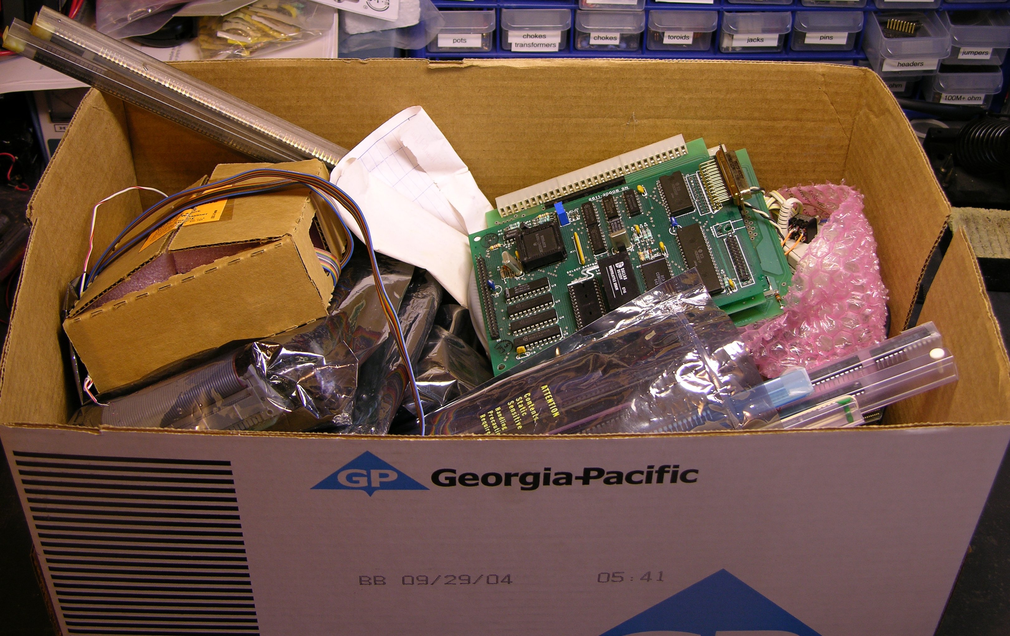
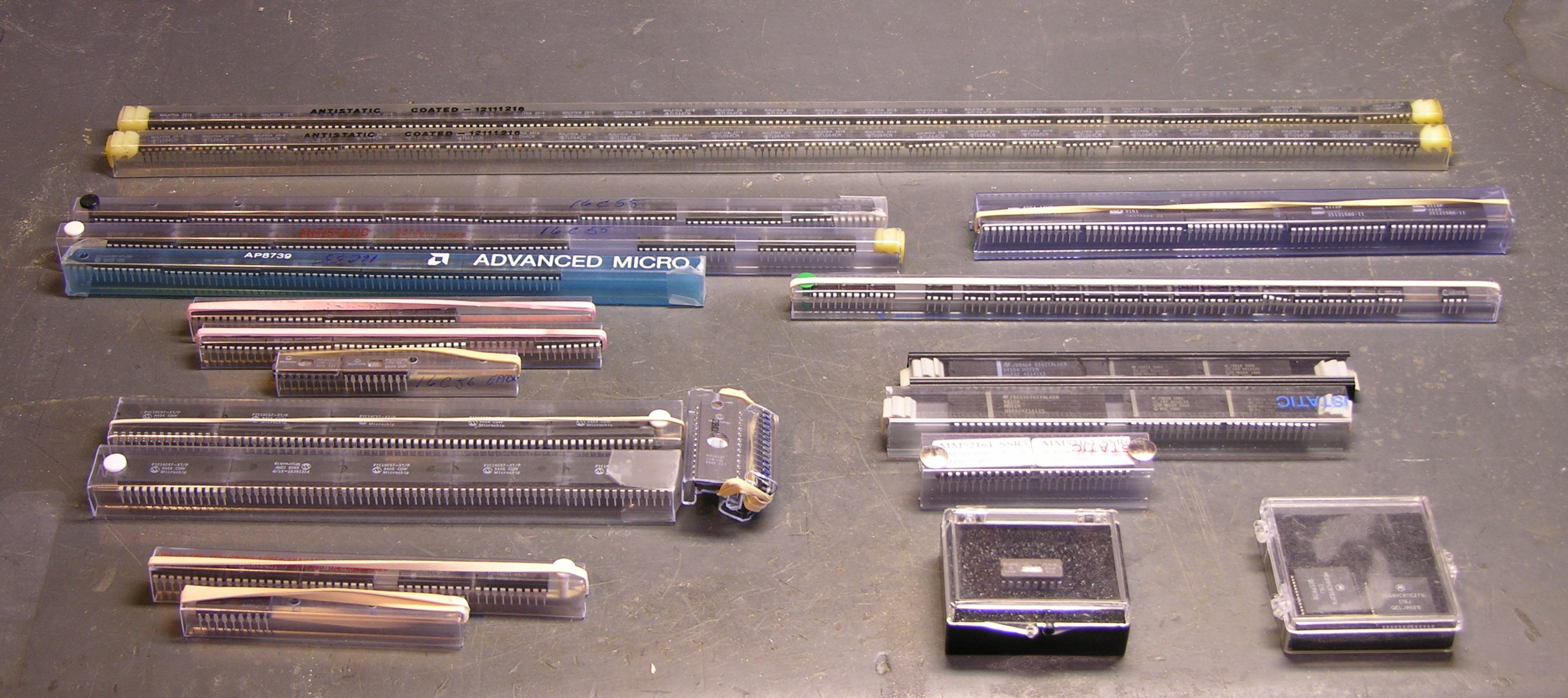
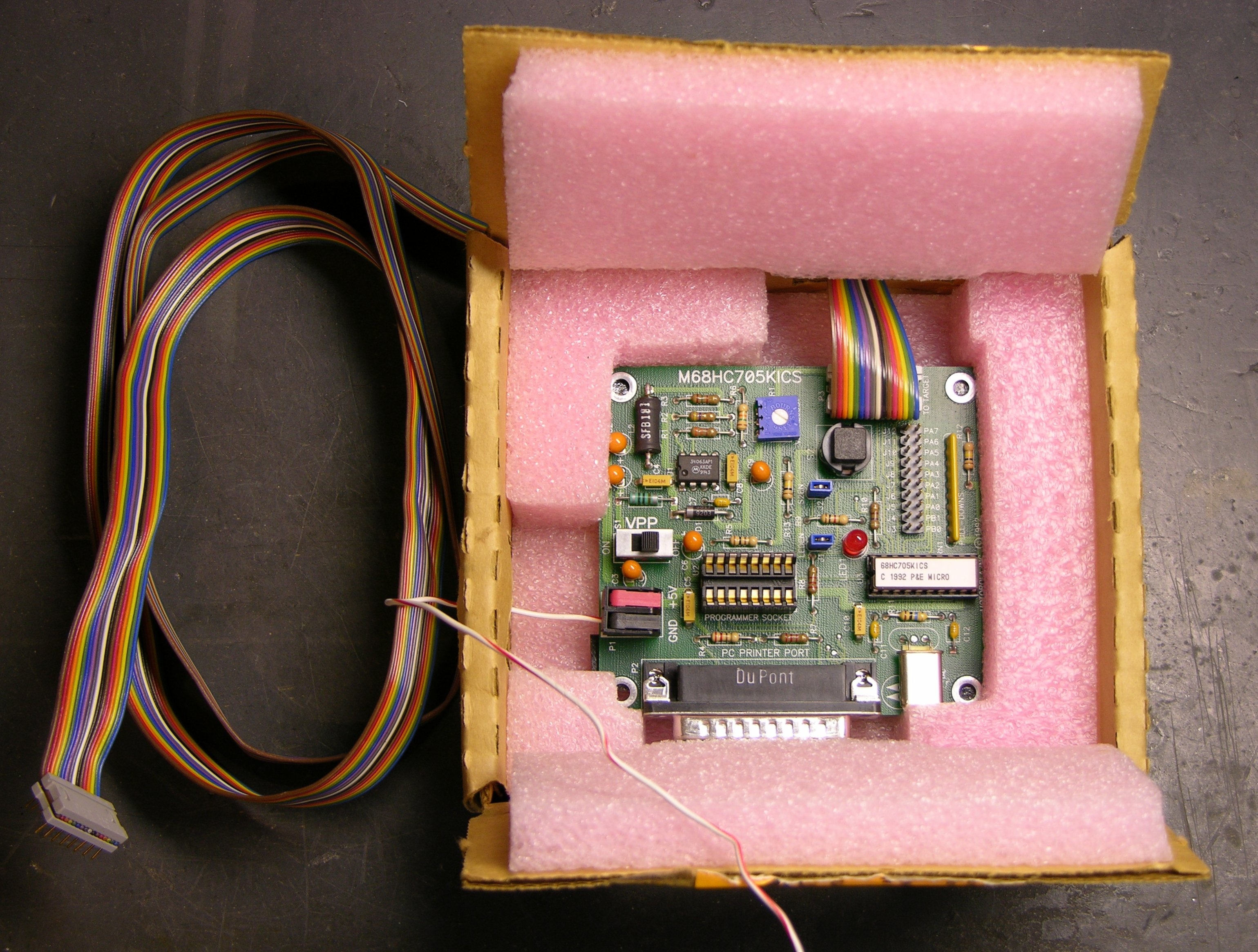
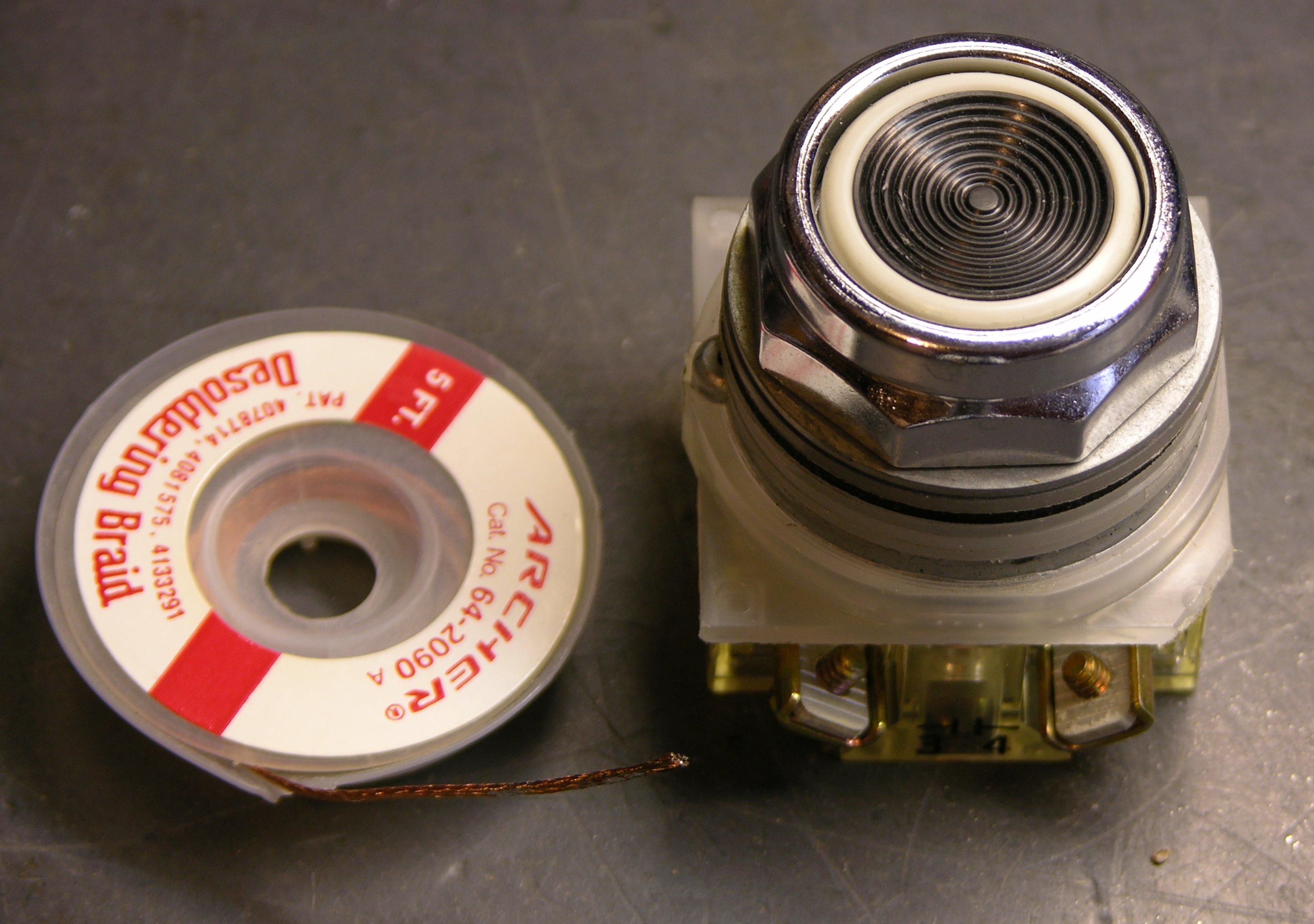
I actually had an ace up my sleeve: I already have a box of flammable gas detectors.

Flammable gas detector, top view

I picked up several of these at Lloyd’s electronics about eighteen years ago, I think for $1 each, in one of their dump bins. At the time, I was probably after the buzzers more than anything else. But I remember that I had hooked one up long enough to test it, and it worked. Trim the sensitivity and blow flammable gas into the element, and the buzzer goes off. (Flammable gas . . . mechanical buzzer . . . never mind . . .)

Now, I could loan him one of these, but they require 110VAC, they’re not safely packaged for mobile use, and they only give a binary output. So I figured I could reuse the sensor element from one and construct a tricorder handheld unit with analog (or at least more than binary) readout.

I didn’t make any promises and haven’t mentioned that I’m pursuing this, so there’s no pressure. But once it occurred to me, it seemed like an interesting project; so here I go.

Drawing the Whole Schematic

Why draw out the whole schematic? Because I had no idea how the sensor element worked. I wasn’t rapt to know how some unknown manufacturer had designed an alarm circuit; I simply needed to know how to work the sensor. With no part number on it and no knowledge of the field of gas detection, the easiest method seemed to be to see what the original circuit did and make guesses about the sensor from there.

In retrospect, everything I need to know about the sensor I could have figured out with my multimeter instead of figuring out the circuit rather than after figuring it out. But no harm done.

Scanning and Drawing

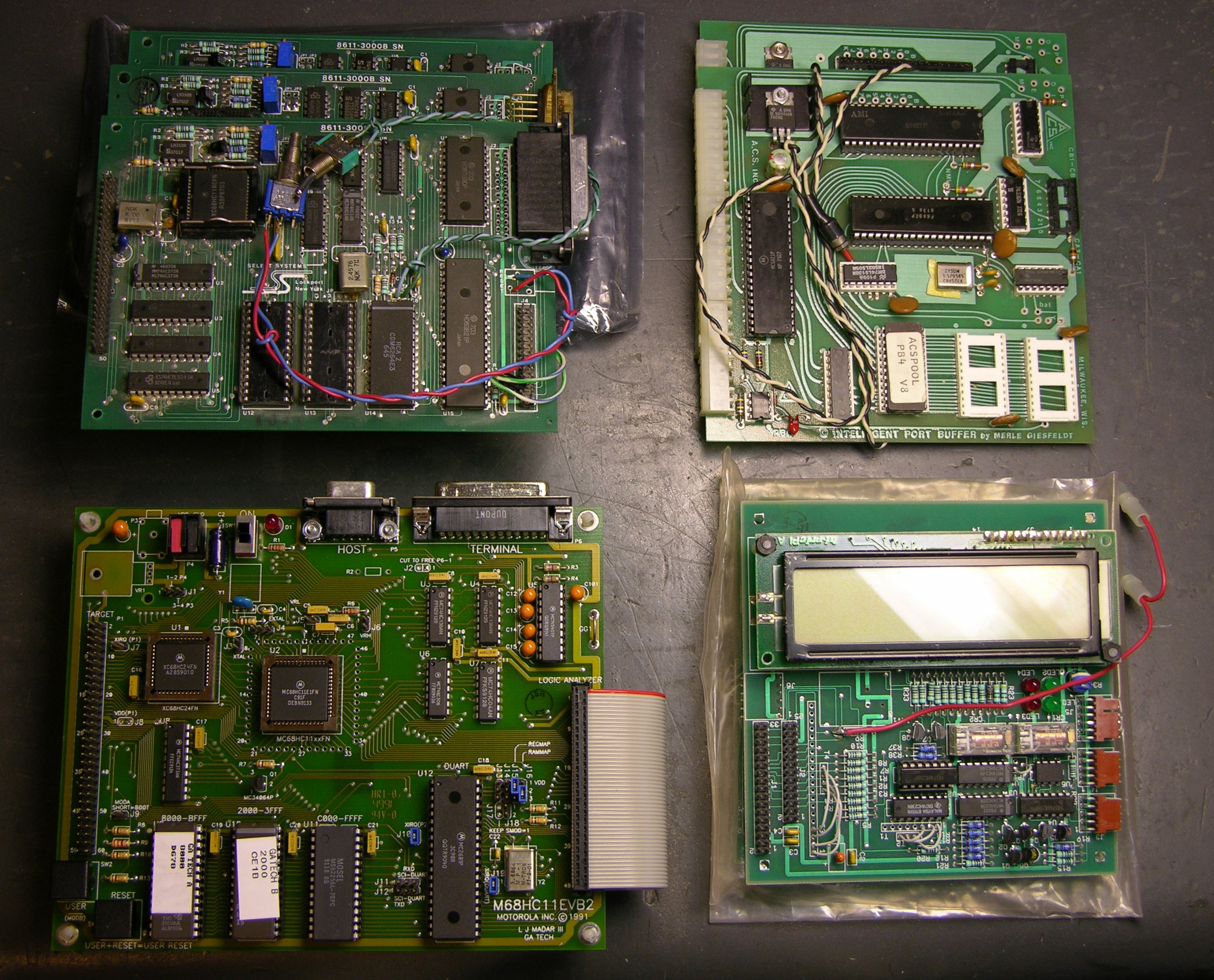
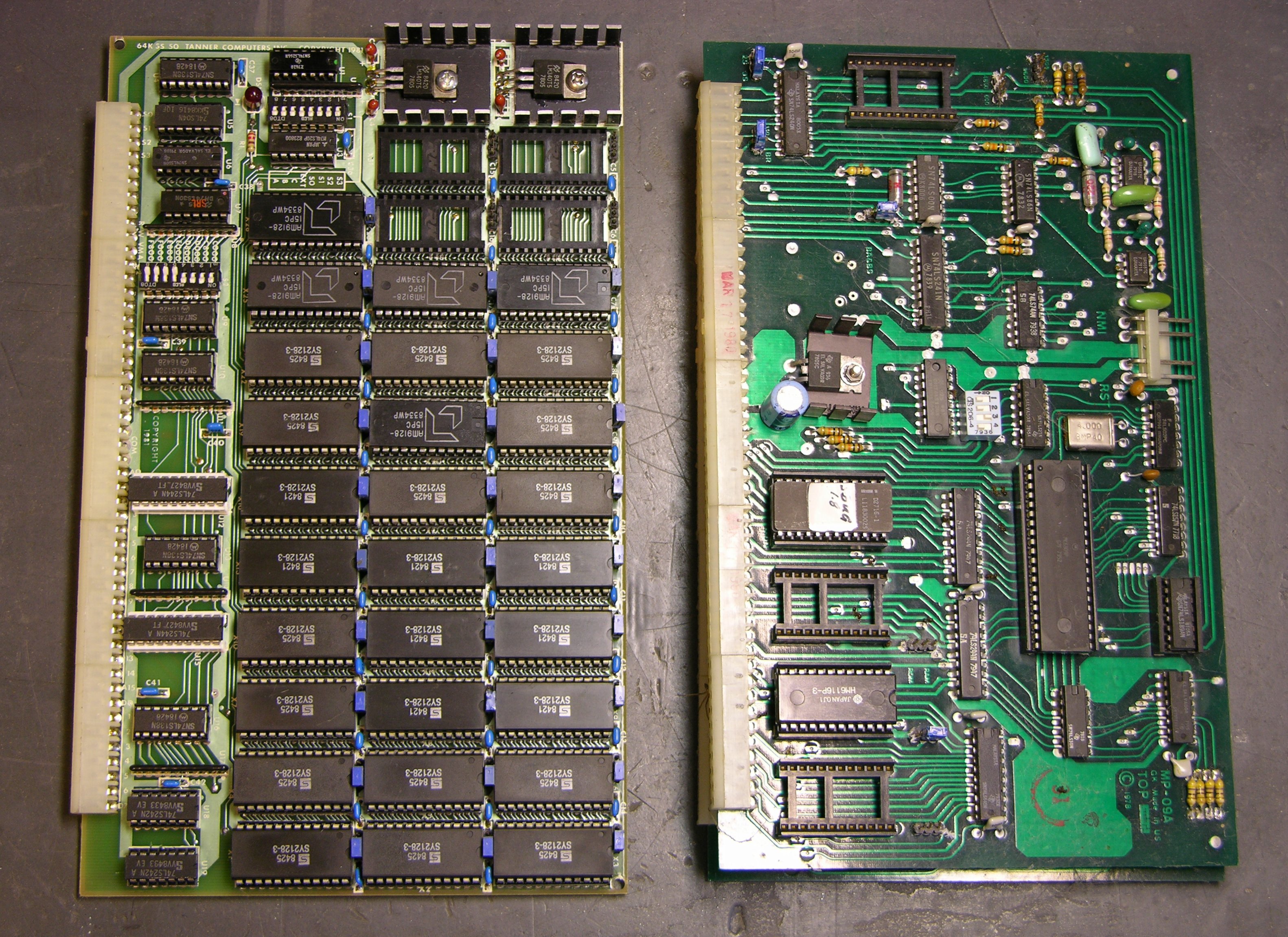
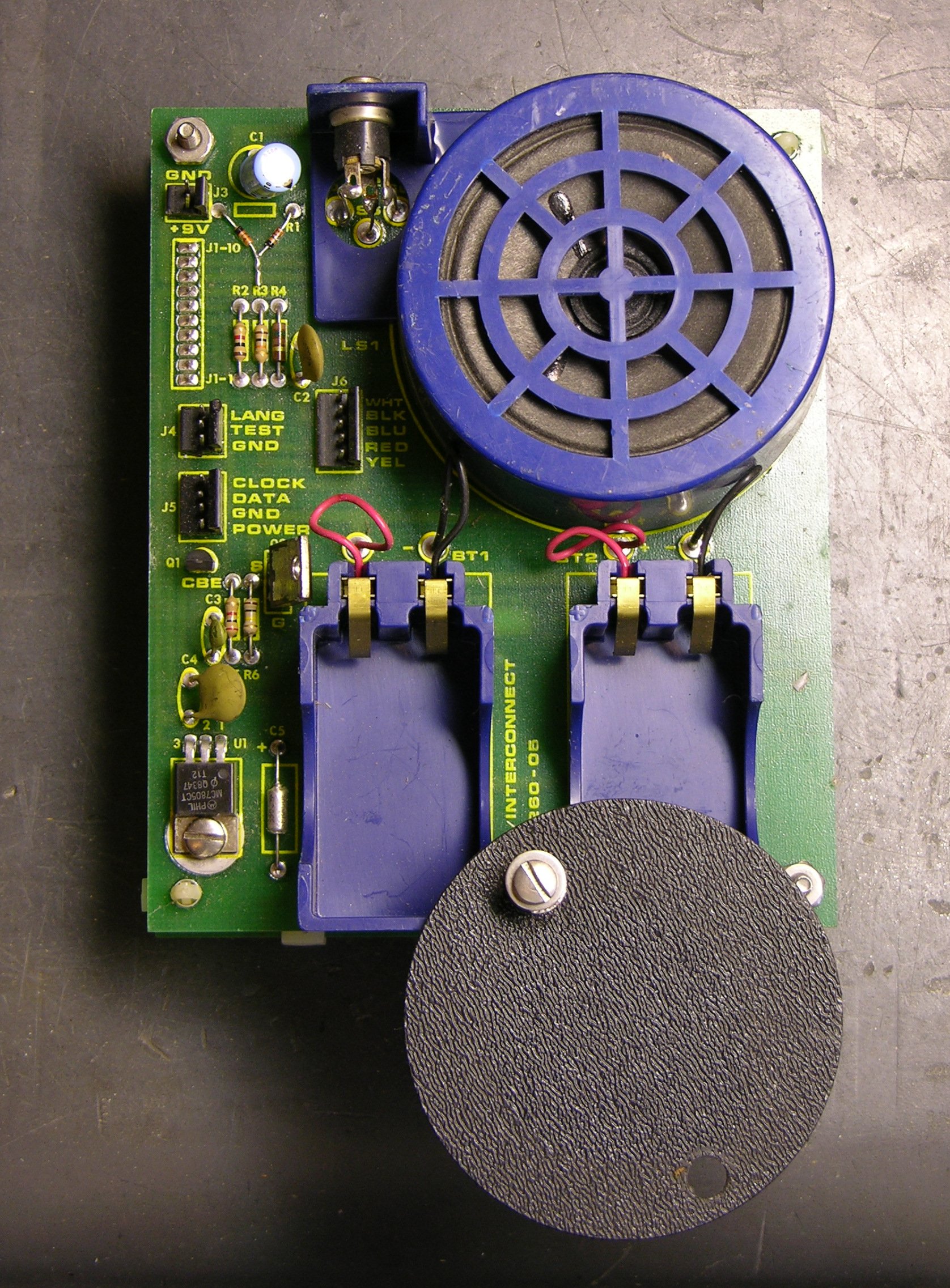
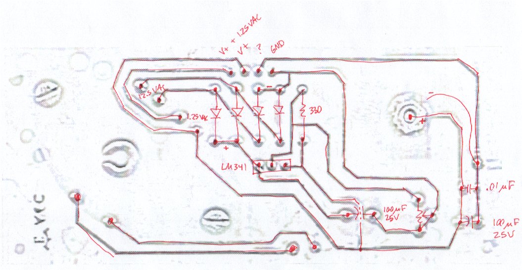
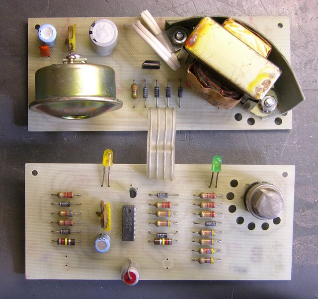
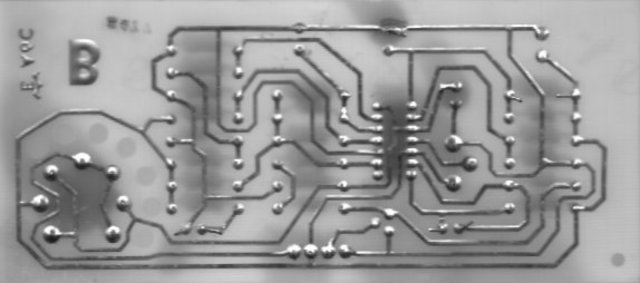
I started by scanning the solder side of both boards into the GIMP and mirroring them to give me a top-side view. The power board is pretty simple, so I ran an edge-detection to emphasize the traces against the light-colored board, printed it, then highlighted the traces and hand-drew the components.

Flammable gas detector, power board scan / schematic

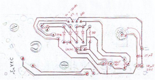
It has a bridge rectifier with a floating LM341 that’s presently delivering ~15VDC, the buzzer, and 1.25VAC from a separate transformer secondary that gets added to DC V+ and sent on one pin to the sensor board.

For the main sensor board, I set the scan at 1:1 scale in the GIMP and dragged rules over it so I could quickly identify the coordinates of each pin. (I didn’t draw them as lines, so they don’t show in this export.)

Flammable gas detector, solder-side scan

I then created an EAGLE schematic / board layout, adding and placing each component and then each trace, until my EAGLE copy matched the scan (more or less).

Flammable gas detector board layout

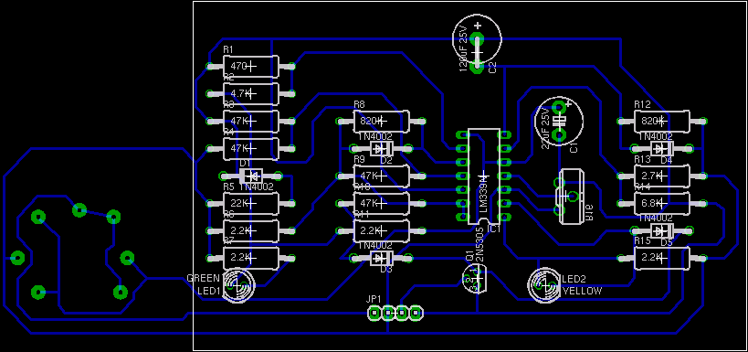
I first placed the parts on the schematic in the same place as on the board, to help keep track of what I was doing, so the schematic looked really ugly:

Flammable gas detector schematic in board placement

And then it was just a matter of dragging the schematic around into a more logical configuration.

Flammable gas detector schematic diagram

The image compresses badly, so you’ll need to open that into a separate window if you’re interested in following along.

How It Works

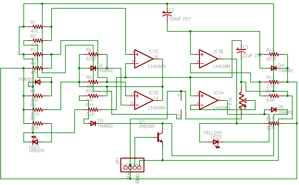
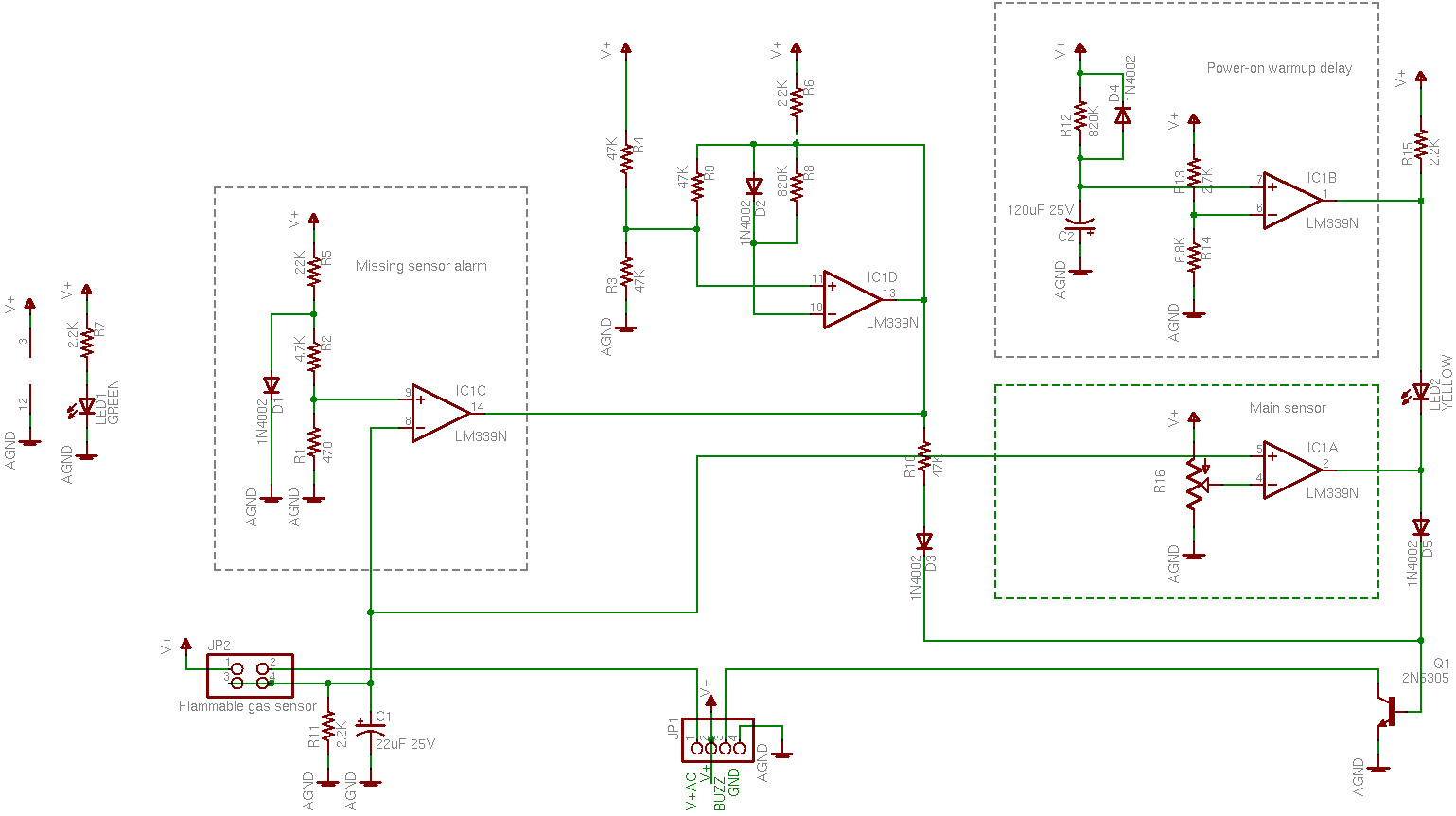
In high-level terms, the sensor element (lower left) puts out some kind of voltage that runs through a bunch of comparators, and switches an NPN transistor that grounds the buzzer. Detect gas, make noise. But it took me a while to figure out why so darn many comparator stages are used.

First, it’s worth remembering what the LM339 comparator does. It has open-collector outputs, so you can tie its outputs together in a wire-AND (or active-low OR) configuration. If any output is low, the line goes low; if all outputs are high(-impedance), the pull-up resistor pulls the line high.

This configuration is used twice in the circuit: In R15, IC1B, and IC1A; and in R6, IC1D, and IC1C. IC1A and IC1B can each pull down R15 and keep its high signal from getting through to Q1; likewise IC1C and IC1D can each pull down R6 and keep its high signal from getting through. Diodes D3 and D5 perform diode OR logic: either one permits a high signal through to Q1, but a low signal is blocked and can’t pull down the other’s high signal.

So Q1 will have its base pulled high and activate the buzzer when

(IC1A AND IC1B) OR (IC1C AND IC1D)

Comparators

Now we just need to know what each comparator is doing.

Flammable gas detector schematic diagram, gate IC1A

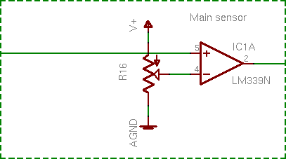
IC1A is simple: The sensor’s voltage is compared to an adjustable reference. This is the main action of the whole device.

Flammable gas detector schematic diagram, gate IC1B

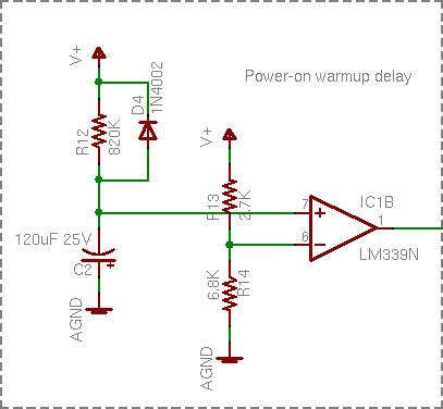
IC1B was the next one I figured out, although I didn’t have it quite right at first. Capacitor C2 charges through R12 and IC1B compares its voltage to a reference, so it’s a power-on delay. I wasn’t paying attention to how high R12′s resistance is (820kΩ), though, and I figured IC1B’s purpose was to keep the alarm from blatting when the power first comes on and before it stabilizes. That’s not quite it, which I’ll explain in a bit.

Before I move on, note the entire signal chain of V+, R15, IC1B, LED2, IC1A, D5, and Q1 along the right edge of the full schematic. IC1B and IC1A can each ground R15 and prevent it from pulling up Q1′s base.

IC1B also controls LED2, though. LED2′s cathode is grounded through either IC1A or Q1, so IC1A has no impact on LED2; but IC1B can pull down LED2′s anode. In English, LED2 indicates that the circuit is warmed up and ready to operate.

I find this extremely elegant. It’s not complicated; but in today’s world of cheap microcontrollers and FPGAs, I think clever thought has too often lost way to throwing lots of gates at a problem.

Continuing:

Flammable gas detector schematic diagram, gate IC1C

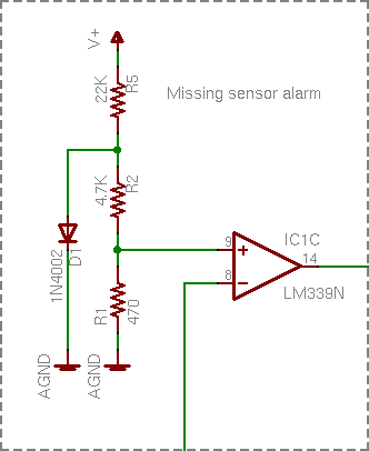
IC1C’s voltage divider seemed a bit odd, but it’s just establishing a very low reference. D1′s forward voltage is about .5V, and R2 – R1 divide that down to .05V. If this reference is higher than the sensor voltage, then trigger the alarm. Ahhh, it’s a missing sensor detector. The sensor is pluggable; if it got knocked loose, or broken, or maliciously removed, the alarm sounds a warning. Very nice.

IC1D I still don’t get. Best I’m able to measure it in circuit, it appears to be oscillating around 1.3MHz at startup until IC1C pulls it low and shuts it down. I have no idea what it’s supposed to be doing. And yes, I’m fairly sure I drew its schematic right.

Comparator Recap

So if the sensor element is missing (IC1C), the alarm sounds. Otherwise, once the circuit is warmed up (IC1B), a high enough voltage from the sensor (IC1A) sounds the alarm. Simple!

And it still doesn’t tell me how the sensor works. Feh.

The Sensor

Flammable gas sensor and socket

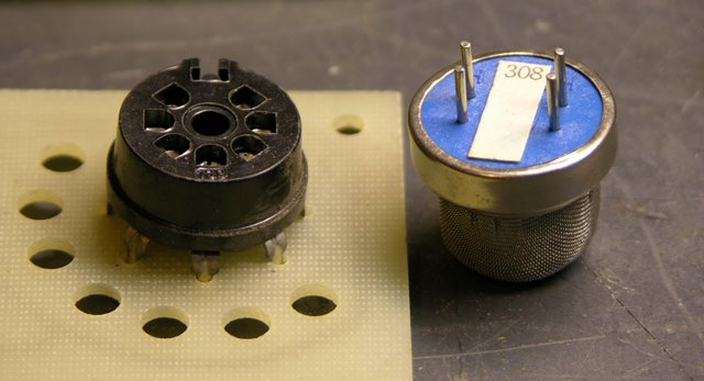
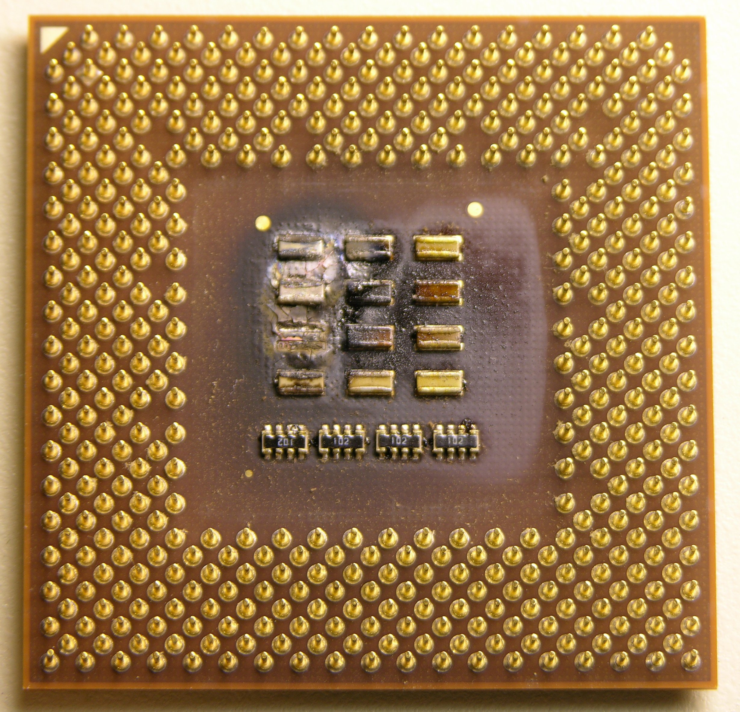
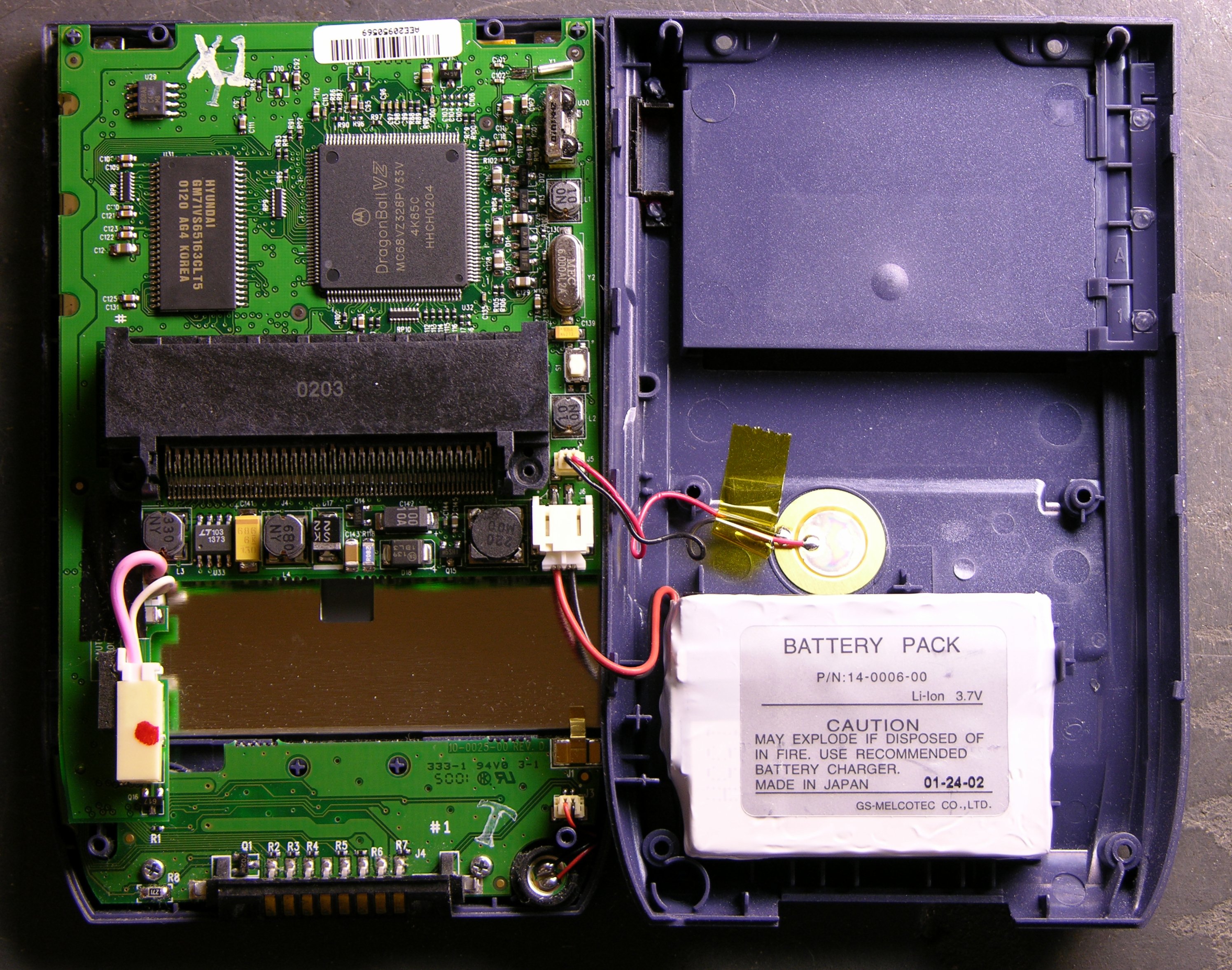
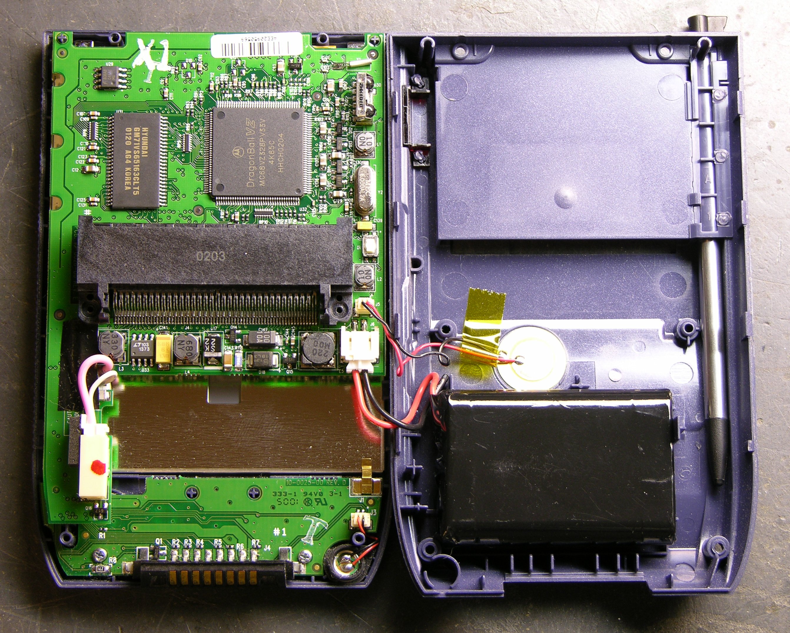
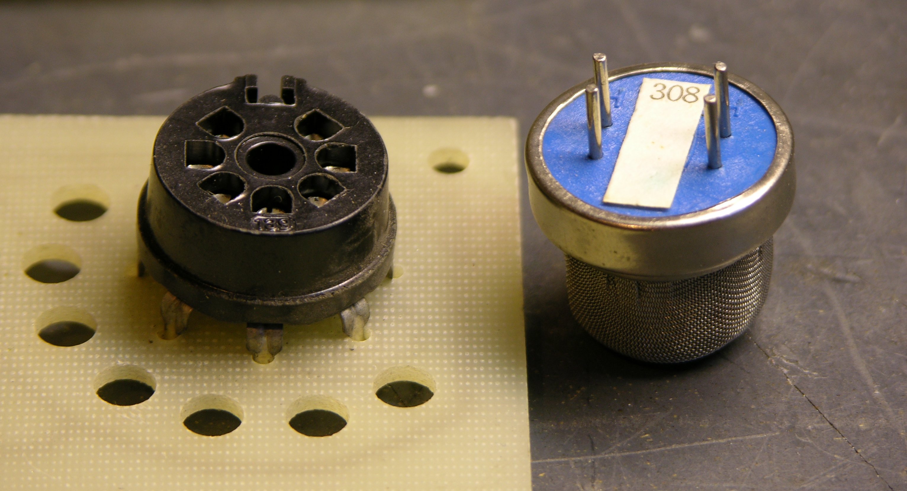
It’s not obvious from the aerial photograph of the whole board that the sensor has four pins in a rectangle, and that the socket has seven pins and the sensor can fit it in two different rotations. From the solder-side picture, though, the socket is wired such that (assuming the sensor is electrically symmetric) the sensor will be connected the same either way. So assume that the sensor is symmetric electrically as well as physically — that is, the pairs of pins are functionally interchangeable.

Looking back at the board layout and tracing carefully, V+ and V+AC connect across one long side of the sensor’s pinout rectangle. The other long side is wired directly together and functions as the output, connecting to R11 and C1 (both grounded) on the way. So: The sensor normally has a high resistance between its power pins and output pins; that resistance lowers when flammable gas is nearby, changing the sensor – R11 voltage divider and raising the voltage.

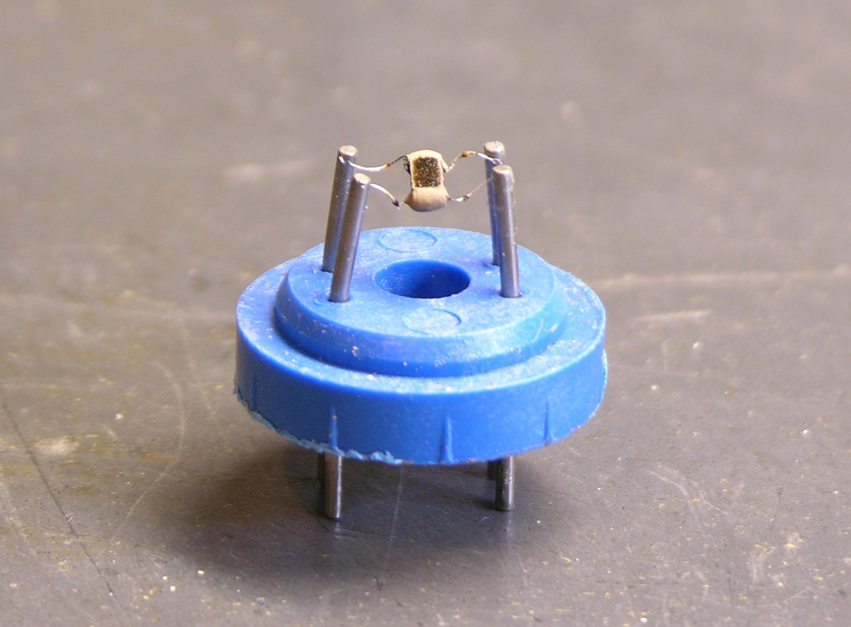
But why supply 15VDC + 1.25VAC to the power pins? I didn’t understand, so I cleaned the power supply board, insulated its 110V traces with electrical tape, plugged the circuit in, and took some measurements — and still didn’t get it. So I looked through my box for the sensor with the most-crushed windscreen and peeled it apart.

Flammable gas detector sensor

And I searched for flammable gas sensors online, eventually finding this slide on catalytic sensors from an OSHA workshop titled What to Look for in Gas Detection and Measurement Instrumentation.

It doesn’t match exactly, but the basic idea seems to be that you heat up a specially-coated thermistor bead; flammable gas oxidizes on it, heating it further; and you measure the change in resistance due to the increase in heat.

And things start to make more sense. You heat the bead with a small amount of AC across pins 1 and 2, and you run that AC on a DC offset so you can more easily measure resistance changes between pins 1-2 and 3-4 by making it part of a much higher voltage DC voltage divider. I can deal with this.

Sensor Measurements

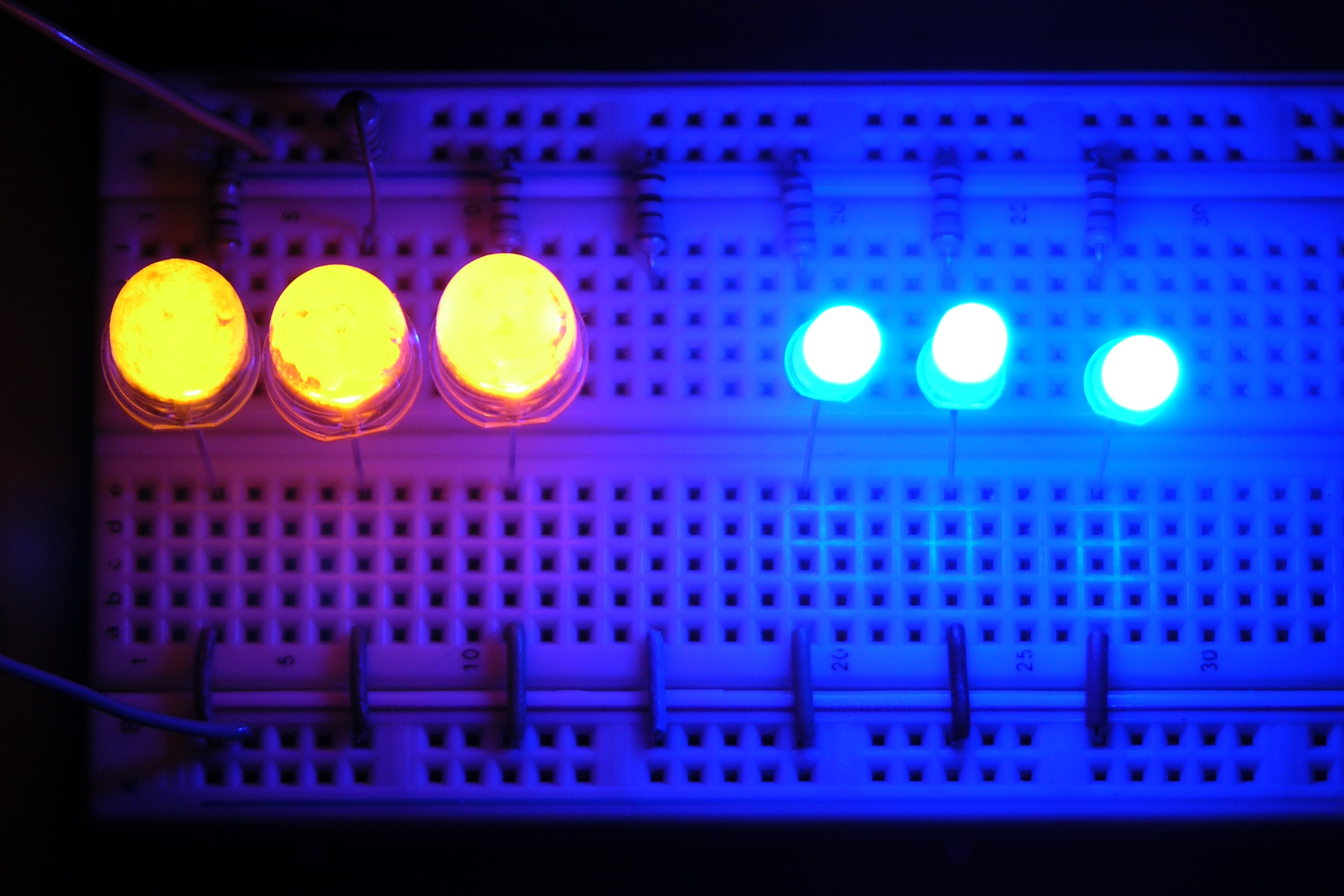
Running the open sensor in the live circuit shows that its bead heats up to about 160°F — and it takes about half a minute to warm up, hence the long delay from R12 – C2 – IC1B before turning on the yellow “ready” LED. (Not just a power-up delay, but a warmup delay.) The sensor also responds a lot more rapidly to approaching and dispersing gas with the windscreen removed.

The sensor output voltage across C1 is 0V when the circuit is first powered up, rises to about 4V when the element is warm, and climbs as close as I care to measure to V+ (15V) when gas is present. The sensor and R12 (2.2KΩ) form a voltage divider across the 15V supply, so:

Condition VC1 Rsensor
cold 0V
warm 4V ~600Ω
gas present 15V << 2.2KΩ

Finally, I measure each “long leg” of the sensor at 2Ω and I measure about half an amp flowing on the “heater” side. And that’s all I need to know about the sensor.

Building a Handheld

That’s next. I’m not keen to build a biased AC supply into a handheld unit, but nor do I need to. I can heat the element with a high-frequency square wave; that simply means that the sensor output will also be a square wave, and I can deal with that by integrating the output or using a peak level detector (essentially the same thing).

It takes about half a watt to heat the bead to 160°F, and that’ll drain a 9V battery fairly quickly with constant use, but I use rechargeables anyway. And I may find I don’t have to heat it quite that much.

Where am I going to find a reasonable socket for the darn thing? I’d really prefer a nice rectangular configuration, instead of perpetuating the weird any-rotation-you-want of the original.