Archive for the ‘Hacks’ Category

Low-Temperature-Cooked-Eggs in a PID-Controlled Crockpot

Tuesday, December 14th, 2010

The web is ablaze with projects for sous-vide (vacuum-sealed) and low-temperature / long-duration cooking. For those not familiar, the basic idea is that if a perfectly-cooked medium-rare steak is 120°F / 49°C in the center, by cooking traditionally on a grill, you overcook it everywhere but the center. Instead of cooking at a higher temperature and waiting exactly the right amount of time for the inside to warm up to the desired temperature, cook the entire piece in a water bath at the desired final temperature for a long time, then sear the outside to make it extra yummy.

PID-controlled crockpot cooking two eggs

My project this weekend, rolling around in my head for way too long and finally kicked into motion by EMSL’s omelette-in-the-shell post, is nothing new nor revolutionary; it’s merely mine. Like many others before me, I plugged a crockpot into a PID controller to turn the crockpot’s heating element on and off and maintain its temperature precisely over a long period of time.

(more…)

Making Mini Extension Cords / Testing New Solder and Heatshrink Techniques

Sunday, March 7th, 2010

When you cut up an extension cord for speaker cable (I’m no golden-eared audiophile; I just need some copper to get a few hundred watts from place to place), save the ends to reassemble into mini extension cords. They’re perfect for plugging wall warts into receps and power strips without making adjacent receps unusable too.

I’ve spliced a lot of different kinds of cables — sometimes repairs for friends, sometimes Frankensteining things together for a project — and I’ve always been dissatisfied with the aesthetics when I’m done. Covering the joint in heatshrink hides the ugly splices from direct view, but the heatshrink tapers where it falls off the edge of the cable’s jackets and has unsightly bumps covering the solder joints.

This weekend I tried out a couple of ideas for achieving a smoother splice. The basic method was sound; and although the results aren’t yet what I hope to accomplish, I think they’re leading in the right direction.

Extension cord with jacket ends cut for splicing

My first idea was based on a woodworking scarf joint — a fancy term for cutting ends on a diagonal to make a joint less visible. I sliced each jacket lengthwise about an inch and a half from the cut end, then attempted to cut the peeled jackets into smooth diagonals.

Offset solder joints in a cable splice

I tied the jacket pieces out of the way with velcro, preloaded the wires with heatshrink to cover the splices, and soldered the individual wires together. Note that the individual joints are all offset so that even if the heatshrink were to fail or be abraded, the exposed joints still couldn’t come into contact and short out.

Cable splice with jacket pieces not quite fitting

It turns out that eyeballing the mating jacket shapes before putting the cable back together is a bad idea (or at least that I’m not very good at it). I left a fair bit of gap, uh, everywhere — if I were to try it again, I’d wait to cut the scarf (scarves?) until the reassembly stage, at which point I could do a better job of mating them.

Note that the way the jackets flare out where they come from the unaltered cables into the joint is due to heat while heatshrinking the individual wires, not due to the bulk of the splice area.

Spliced cable with lumpy heatshrink

The result is arguably smoother than my previous methods; but because the lumps don’t logically derive from the splices inside, I actually find it more aesthetically displeasing.

Spliced cable with jacket rewrapped over joint

On the second cord I spliced, I slit the left jacket but didn’t shape the split end and I cut the right jacket completely off the cable. After soldering and heatshrinking the wires, I wrapped the left jacket back around the joint, covering it pretty cleanly. The gap where the two ends’ jackets meet is quite evident, but this shows that rewrapping the wires in the cables’ own jacket is a considerable improvement over just heatshrinking the joint.

Two spliced extension cords

Two short cords, ready to use with wall warts.

For next time, I’m most interested in retrying the scarf joint and cutting the two jackets to mate after finishing splice. I think it offers a good chance of minimizing the gap at the end of each jacket, and I think the long diagonal gap under the heatshrink could be nearly invisible with a little care.

Obligatory cautions: Electricity is dangerous. Splicing cords is a bad idea. Don’t burn your house down. Make sure extension cords are unplugged before soldering. Do not taunt mini extension cords.

Blu-ray Theft-Prevention Case and Hard Drive Magnets

Monday, January 18th, 2010

I don’t have a Blu-ray player yet, but I’m doing the same thing I did when I switched from VHS to DVD — buying in the new media when I think prices are reasonable, then buying a player after I have enough media to justify it.

Blu-ray movie in theft-prevention case

Here’s one of my first such purchases, with the cover image obfuscated to protect the copyright-holder’s interest in their artwork. (Note that this is one of my highly-favored movies and I already have two different DVD editions. Wouldn’t want anyone to think this was the first copy I was buying.)

You can see that Target somehow neglected to remove my purchase from their theft-prevention case. I don’t know how that happened, but I do have the receipt. I could easily have ruined the case (bandsaw) to remove my movie, but that would have been so inelegant.

Please use this information only for good.

Blu-ray movie case theft-prevention mechanism

The case hinged open at the bottom of the movie and was held closed by a sliding black plastic strip at the top, shown disassembled here. The strip locks the case shut and in turn is prevented from sliding to the open position by two ratcheting leaves protruding from a metal strip that’s pinned to the case.

Examining the case, I couldn’t find holes where pins could enter to withdraw the leaves, so I guessed magnets. The metal strip did seem to be attracted to magnets, but the ones I had on hand weren’t strong enough to pull the leaves. I knew I had to find a sacrificial hard drive to take apart.

Seagate Barracuda hard drive with PC boards torn away

I got this drive that had been removed from a decommissioned PC at work and, um, “read-protected” by one of our technicians. (I’m afraid it may not have been zeroed first, and I’m hanging onto the platters until I can figure out whether I have something strong enough to degauss them.)

Magnets on Blu-ray movie case

The permanent magnets from the head-positioning assembly retract the leaf springs quite nicely, allowing me to slide the locking strip and open the case. Of course I actually held one magnet on each spring to unlock it, but I wasn’t able to keep them that way for the photo.

Voila! One open case, and one more Blu-Ray movie for Keith.

Heated CupCake Build Chamber

Thursday, December 24th, 2009

Many of the various RepRap plastic extrusion machines, including the MakerBot CupCake, suffer from warping of large objects while the printing is still in process. The first printed layers cool, contract, and lift the plastic away from the build surface at the corners.

warped camera mount

A “good” warped print is still usable because the top surface is flat. A bad warped print raises the first and lowest layers high enough to snag the extruder nozzle on subsequent layers, often causing the steppers to lose alignment and (if you’re lucky enough to be there and catch it when it happens) ending that build attempt.

Several people have been experimenting with heated build platforms and heated build chambers to prevent warping. Most notably, Eberhard Rensch (CupCake #127) has blogged Canned Heat and Living in times of warp-free printing about his work mounting power resistors to an aluminum plate to create a heated build sub-platform.

He reports fantastic success, I’m intrigued, and I want one; I just don’t feel like machining aluminum plate to fit the build platform’s mounts right now. I’d be willing to buy a kit for a reasonable price, and I’d be willing to make my own in the spring. For now, I wanted to try something quick and easy and it seemed quicker and easier to heat the chamber than to build a heated plate, so I asked my wife whether I could burn up her hairdryer by leaving it on for a few hours at a time.

Right, so off to the thrift store it is.

Hairdryer

Gillette Curlytop Froufrou hairdryer

I present the Gillette Curlytop Froufrou plastic extrusion chamber heater.

I clipped an orange spring clamp onto the handle to make sort of a tripod, propped this baby up behind the CupCake, fired it up, and … the extruder nozzle could no longer heat past about 200°C. I moved the Froufrou around behind the CupCake trying different positions, finally finding one in which the nozzle could heat up to 225°C, but it really wasn’t working. The hot air from the hairdryer is lovely for warming the chamber, but it’s still way cooler than 225°C and cools the nozzle too much.

Modified Hairdryer

I needed a lot less air; and with less air, I could probably do with a little less heat. The heating element and blower motor are wired in parallel inside the handle (I peeked), so I could dismantle this and do something to one or the other; but it seemed simpler to reduce the power to the whole thing.

Ideas that leapt to mind:

  • Run it off a variac … that can support up to 10A and that can dial line voltage down to maybe 50VAC or less. Nope, don’t have one of those.
  • Half-wave rectify the line voltage in series with the hairdryer, so it sees lower amplitude (pulsed DC). Might try that.
  • Huge power resistors in series … did I mention huge
  • Call Tozier and see if he has any ideas.

Ron said to come on over, and tried (using line voltage safety measures one would only recommend to a particularly troublesome coworker):

  • Huge power resistor — got really hot, but did slow down the fan and presumably the heat.
  • Huge diode — didn’t get as hot and had about the same effect on the hairdryder.
  • Using the secondary of a step-down transformer as a series inductive load — made scary buzzing sounds and seemed to have about the same effect.

Okey-doke, time to try the big diode at home.

Large diode in AC circuit

This assembly was quick and dirty, and don’t do it like I did, but notice that at least I took the time to lay out the wire lengths so that even if it got squished no exposed metal could come into contact and short out. And off to the right is the big heatshrink I slid over the whole schmear as soon as I’d taken this picture.

Partial Success

Four desk cable hook print attempts on MakerBot CupCake

These are four build attempts from before the heated chamber. Most were already warping unusably only a few layers in.

Warped desk cable hook printed on MakerBot CupCake

This is the best and most salvageable attempt from before the heated build chamber, flipped over from its build orientation. It’s badly warped and “jumped track” early in the build, but not so far as to make me abort.

Desk cable hook printed on MakerBot CupCake

This is one of my first attempts after adding the heater. All of the burrs scraped off easily. (The model is updated to make the loop section thinner — that’s not some bizarro result of heating during the build.)

Desk cable hook printed on MakerBot CupCake, edge view

Shown on edge, you can see a little warping due to separation from the build platform at the far right and at the corner near the center, but overall not bad.

I’m still eager to try a heated build platform — I think it’ll keep the plastic warmer and prevent warping even further. But until then, I’m firing up the Curlytop Froufrou every time I want to print.

Repairing Mr. Coffee

Thursday, September 3rd, 2009

A few weeks ago, my wife’s coffeemaker quit working, and this became A Problem. Not too long after that (or should I say, slightly too long after that) I opened it up, found I couldn’t easily fix what was wrong, and hacked it to bypass the broken part.

Heating element from Mr. Coffee

The symptom was that it wouldn’t power on anything — not even the timer display and the power LED. I suspected that something must have failed on the control PC board; but just to be thorough (and because they were easy to get to), I continuity-tested the thermal switch and the heating element first. No problems there.

(more…)

Programming the CupCake Motherboard and Extruder

Wednesday, September 2nd, 2009

Because the (early batch) CupCake circuit boards are assembled by the customer (me), they’re unprogrammed and the customer (me) has to use an in-system programmer (ISP) to burn the bootloader and then an FTDI USB-serial cable and Arduino development environment to program the firmware. Happily, the prerelease kit included both a USBtinyISP and the necessary FTDI cable, so I was good to go.

I got the bootloader programmed into the motherboard just fine, but I couldn’t get the Arduino IDE to program the firmware into it (and yes, I did install the Sanguino support). The motherboard has a switch to signal the (PC ATX) power supply to turn on and feed all the peripherals; but it’s emphasized that standby power is always provided to the ATmega on the motherboard, so there were no steps needed to power up the ATmega for firmware download. Further, the motherboard power switch didn’t power up the power supply, so I figured it must not be needed yet.

But every time I tried to upload firmware, I kept getting a long timeout and:

Binary sketch size: 15002 bytes (of a 63488 byte maximum)

avrdude: stk500_recv(): programmer is not responding

as though the Arduinoness of the motherboard wasn’t there.

Lots of MakerBot forum posts identify the same problem and talk about jumpering the power supply cable to make it turn on.

C’mon, that can’t be for real. The programming instructions don’t say anything about needing to mess with your power supply cable, and that would be a massive omission.

Maybe another look at the motherboard power switch? Switching it didn’t make anything happen, and the schematic for my V1.1 motherboard shows that the power-on signal to the ATX power supply is under the control of Arduino digital pin 14 — a chicken and egg problem.

MakerBot CupCake motherboard with power supply jumpered for initial programming

After about an hour of searching CupCake and RepRap forums, poring over the schematic for anything I might have missed, trying different random things, and generally getting pretty good and angry, I gave up and used Wikipedia’s ATX power supply entry to help me jumper the power supply’s power-on lead. The power supply came on and the motherboard programmed on the first try.

You’re kidding me. This is a necessary step, it causes so much trouble that everybody posts about it in the forums, and it’s still not covered in the assembly instructions? I honestly still think I must be missing something.

Programming the MakerBot CupCake plastruder controller

Fool me twice, shame on me. When it was time to load firmware on the extruder controller, I found that leaving the USBtinyISP connected from the computer to the PC board’s ISP header is a great way to supply the microcontroller with power for the first Arduino firmware upload.

Yes, by this point the motherboard was correctly controlling the power supply; but this was a handy trick I need to remember.

VGA Dongles for Mac Mini Headless Booting

Sunday, August 23rd, 2009

At work we’re placing Mac Minis as network appliances into backbone wiring closets, in part to decentralize DHCP and DNS services so they survive partial failures (or scheduled outages) of the network any time the local backbone drop also survives, in part to run local proxy service for WCCP because our backbone doesn’t support GRE.

We reinstall the Minis with OpenBSD; and whether this would be true with OS X on them or not, at least with OBSD, they don’t like to boot without a monitor connected. A few weeks ago I made a batch of VGA “dongles” to trick the Minis into thinking a monitor was present.

VGA dongles, sloped pyramid

(more…)

External Filter Capacitor for Cisco Physical Access Gateway

Monday, August 3rd, 2009

At work, we’re upgrading our sixteen-year-old physical access control (keycard) system. We went with a newish Cisco solution in part because our reseller promised the whole works could run from Power over Ethernet (PoE), so we wouldn’t need separate power supplies.

It turns out the subcontracted hardware installer had never seen this done before, the Cisco documentation doesn’t even reference powering door strikes from the access gateways, the contractor and subcontractor couldn’t stop the gateways from locking up when the door strikes open and/or close, and migration to the new system didn’t happen last week while I was on vacation like it was scheduled to.

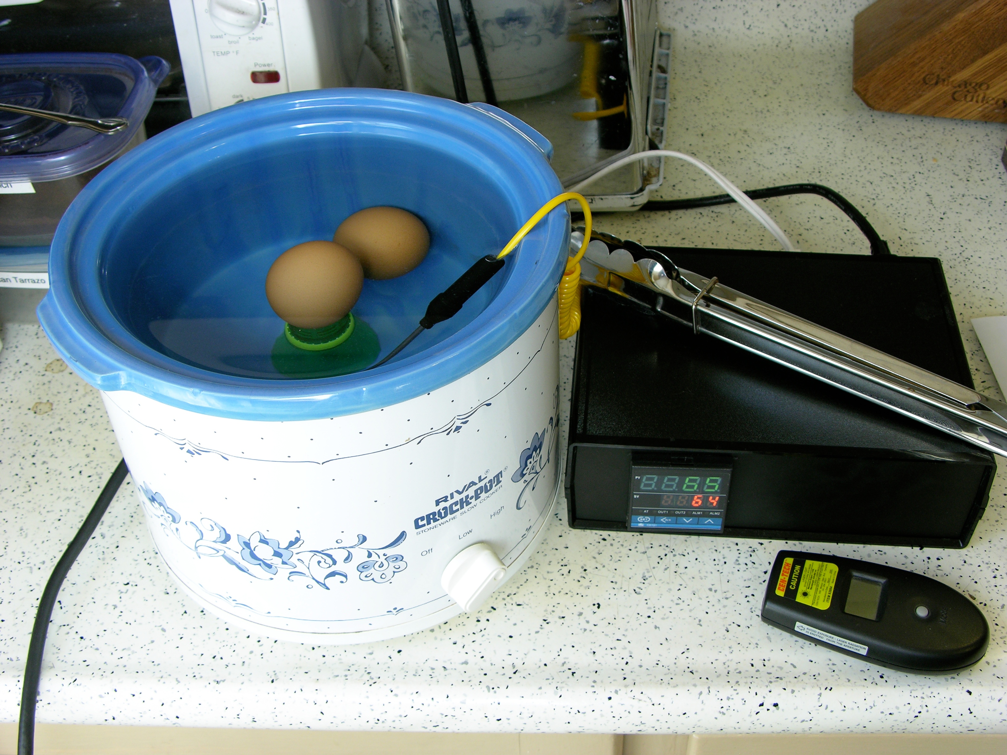
I came in yesterday afternoon to have some quiet time to apply a little rigor to the testing. In a couple of hours, I had a bench system broken in the same way as the installed systems, and then the bench system fixed.

Probably the most annoying part of the process is the 70 seconds it takes from powering up the gateway until the gateway powers up the card reader, and another 60 seconds until the gateway is ready for the reader to read. That’s a long wait when you’re frequently rebooting the gateway to try different things.

Basic Wiring

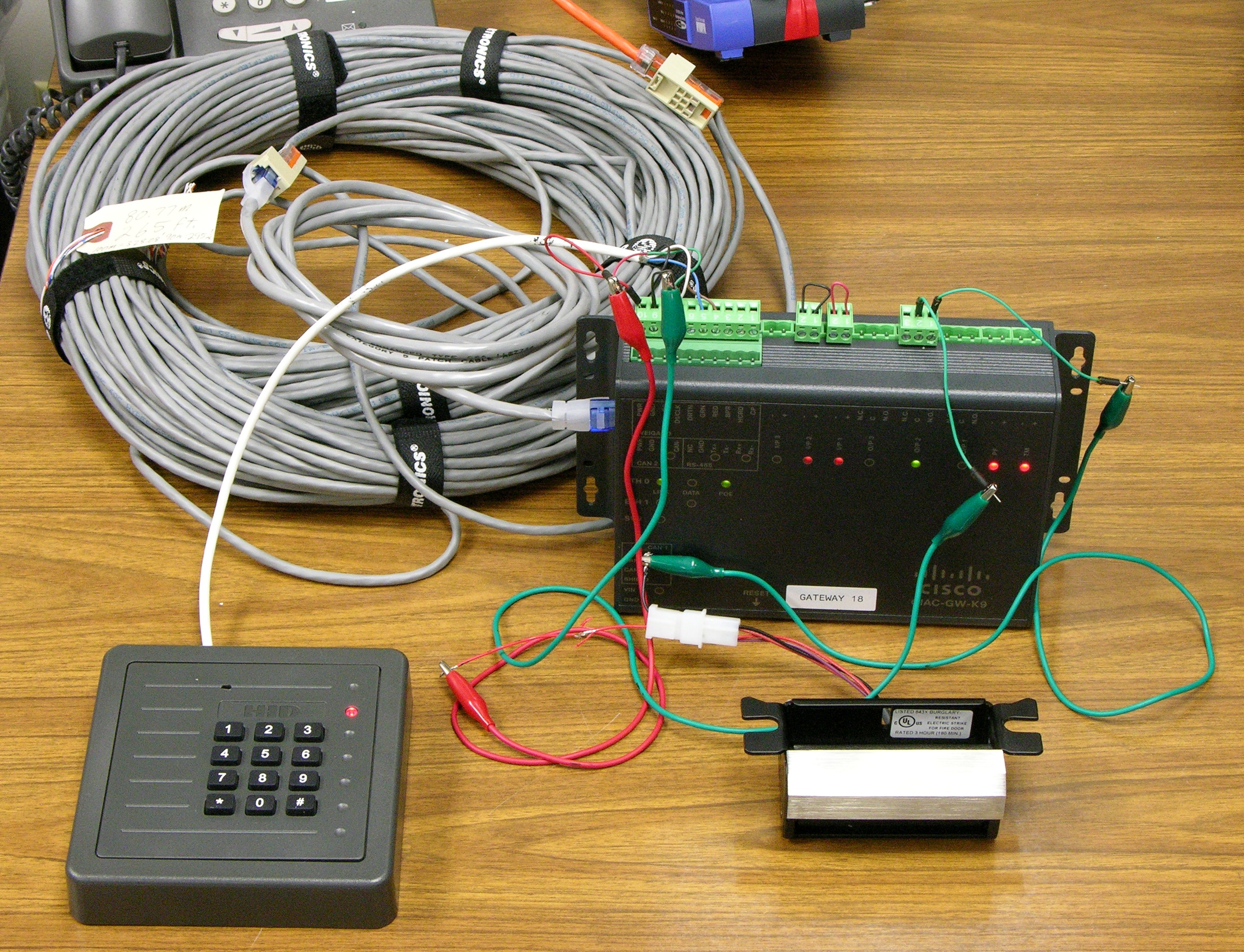
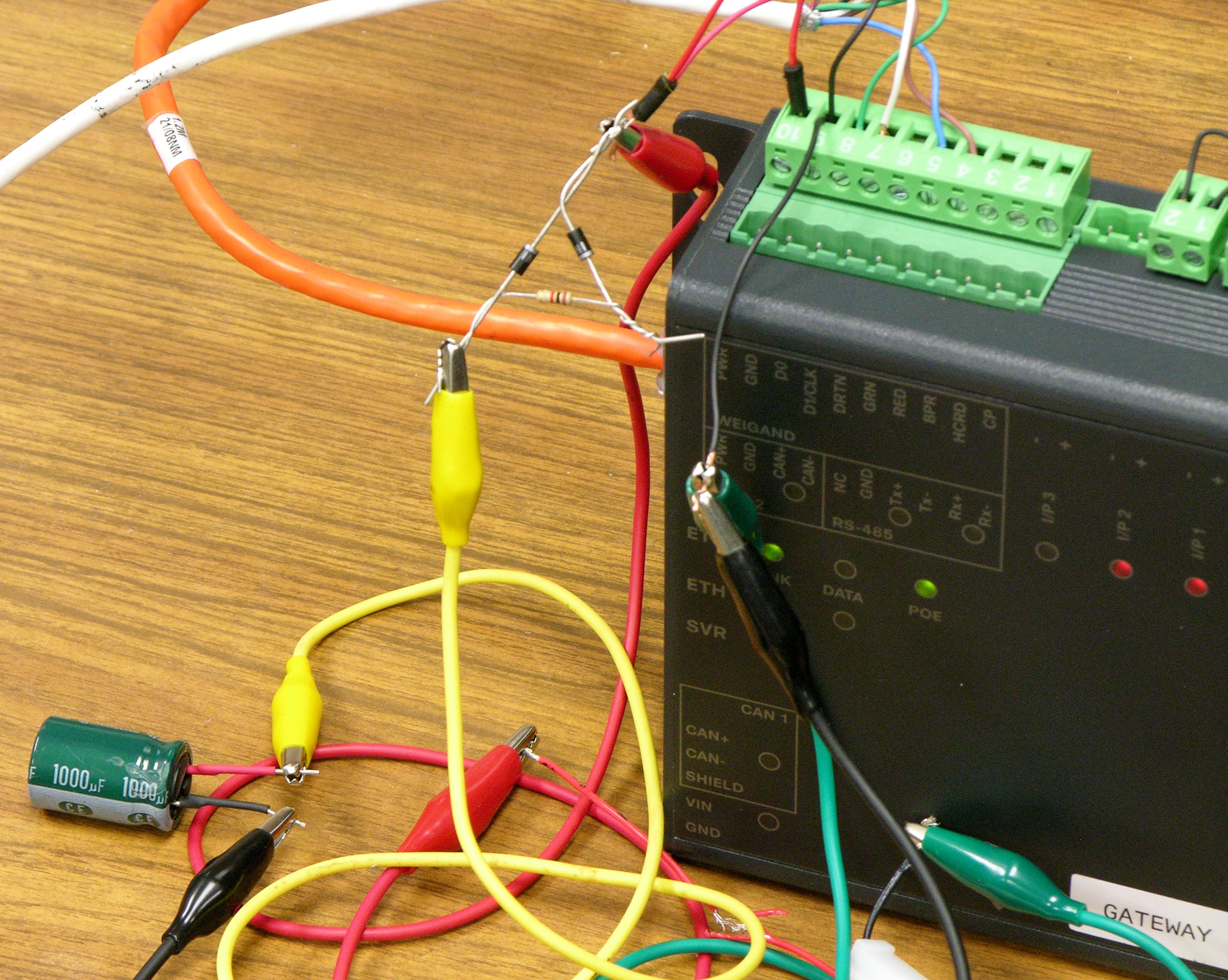
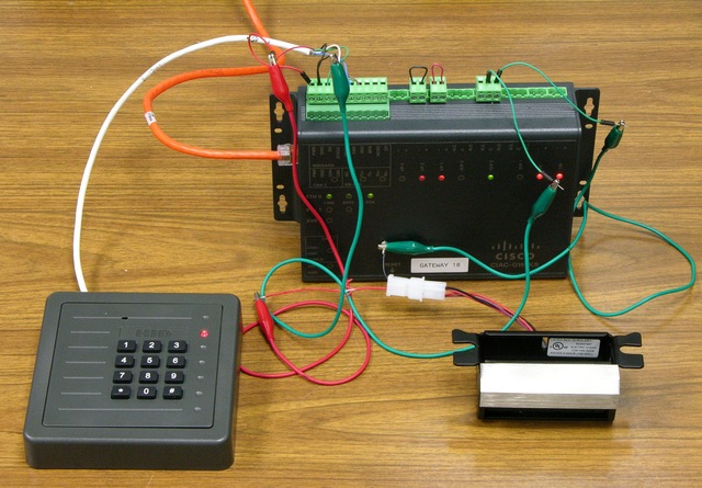
The Cisco physical access gateway has a PoE input for network plus power. It breaks out the power and provides 12V nominal to power the card reader. The subcontractor used these same pins to provide door strike power, with the ground connection interrupted by the gateway’s NO relay output.

I removed all of the electrical tape and twisted wires and provided gator wires for my own testing.

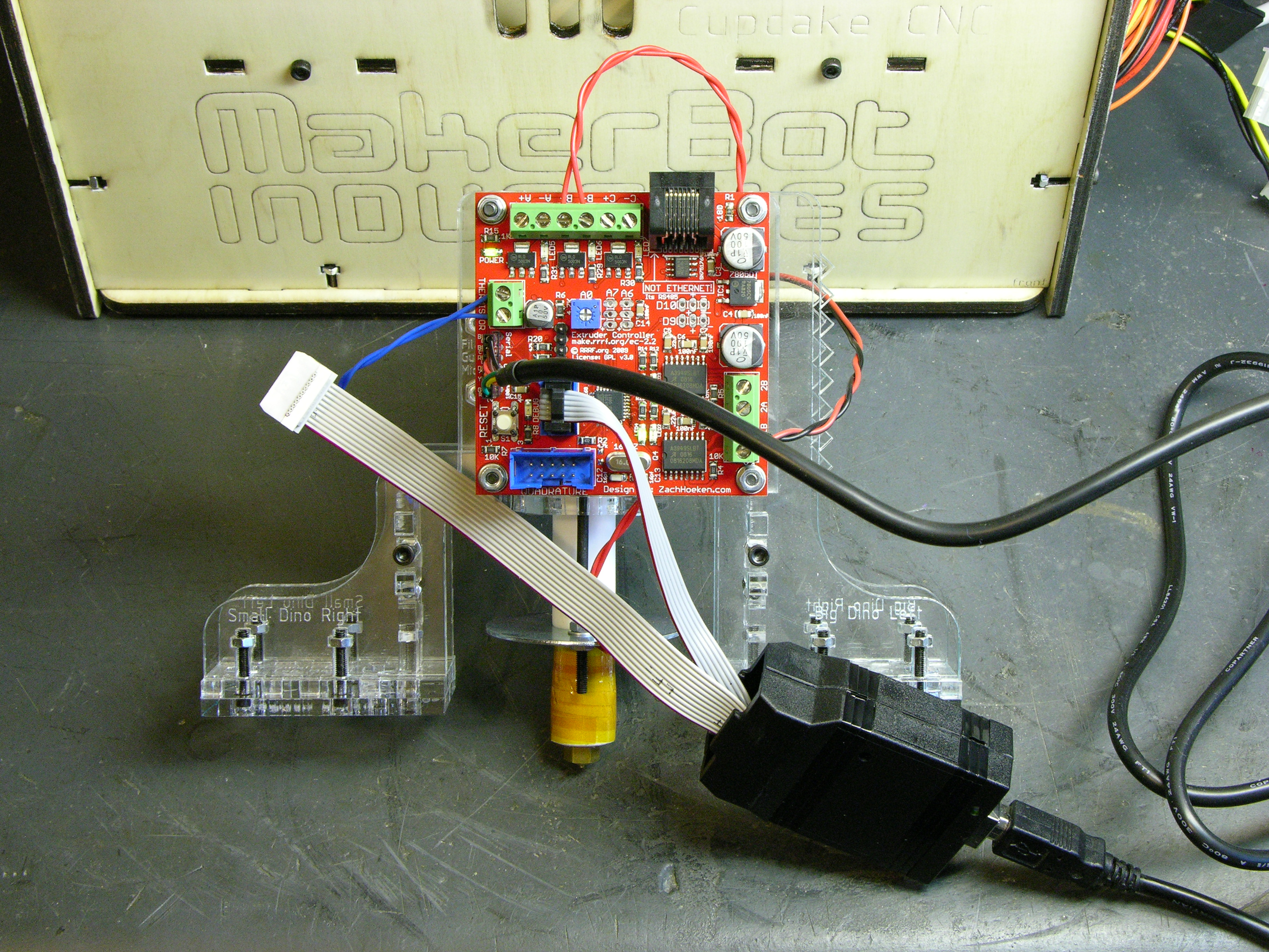
Cisco Power Injector, Short Patch Cord

Cisco physical access gateway running from local power injector on short patch cord

Works fine with a Cisco power injector and a 1.2m patch cord.

Cisco Power Injector, Long Patch Cord

Cisco physical access gateway running from local power injector on 265' cable plus two patch cords

Works fine with the Cisco power injector, 265′ of cable, and two patch cords.

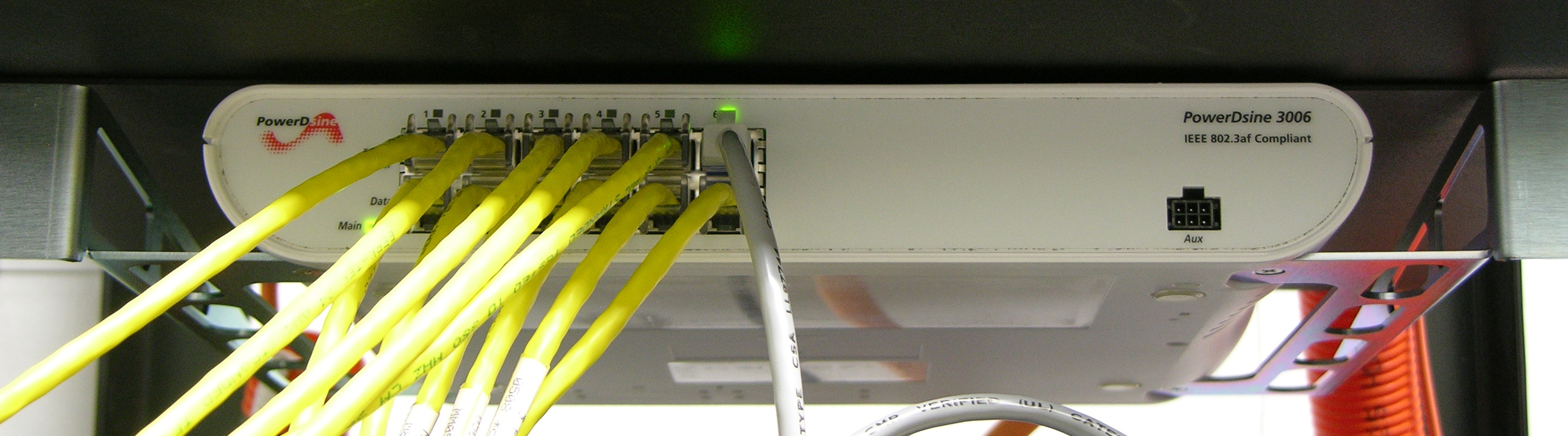
Rack Power Injector, Long Patch Cord

rackmount power injector

It fails with the same setup but powered from our regular PowerDsine rackmount power injectors in the wiring closet. The moment the door strike energizes to unlock (it’s fail-secure), the whole gateway loses power and reboots.

Okay; now we’re getting somewhere — now we have the same problem on the bench that we have in the wild, so I can fix it and it’s meaningful. (As far as I can tell, in all of their searching for solutions, the contractor never recreated the same problem on the bench that was occurring at the installed doors, so their solutions probably weren’t likely to translate well to the real world.)
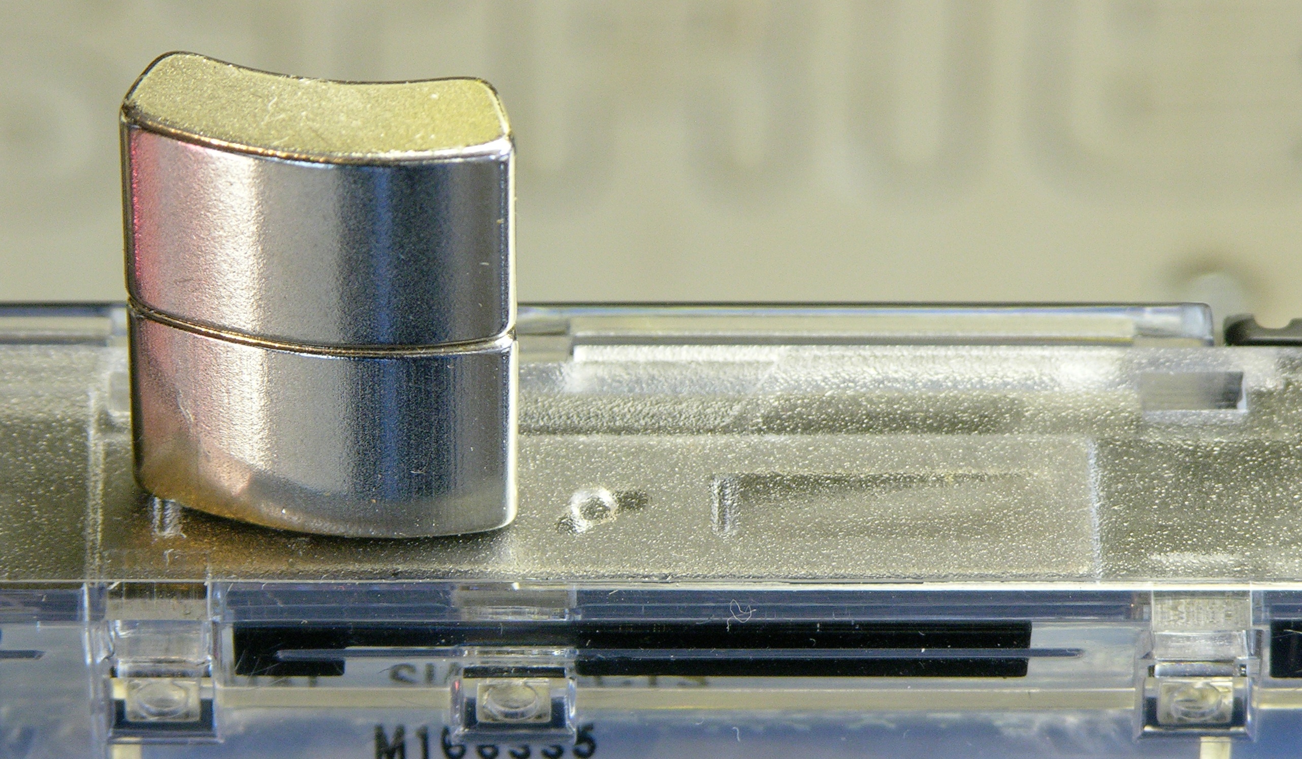
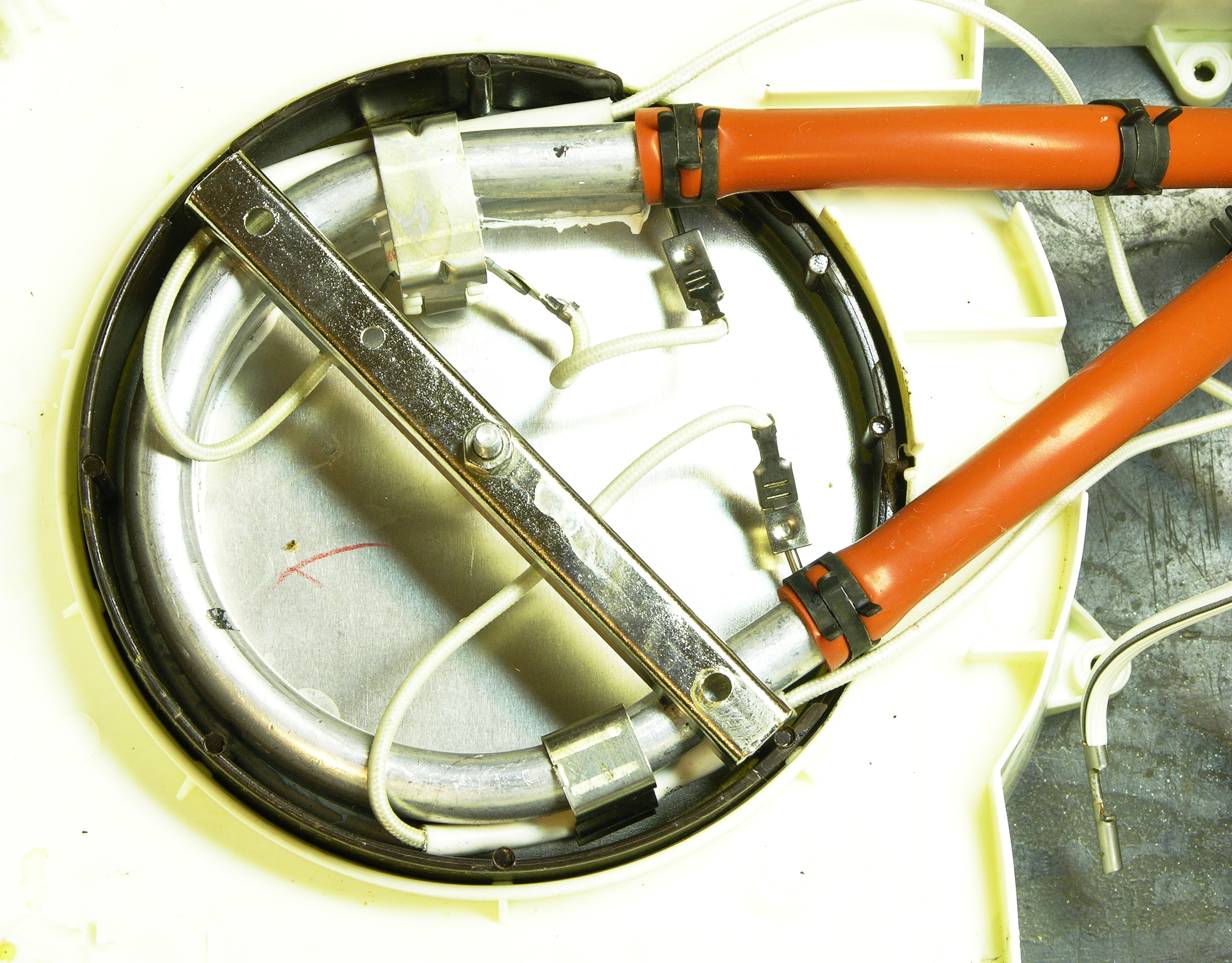
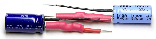
Capacitor

I installed a 1000μF capacitor across the reader/strike power terminals … and the reader went dead. Whaaaaa?

Further experimentation with the voltmeter, the capacitor, and numerous 130-second reboots suggests that the gateway internally switches the power feed to the reader port (and doesn’t turn it on until 70 seconds after booting), monitors the load, and disables it if it exceeds a threshold. And the inrush current to charge the capacitor is enough to trip the disable.

Capacitor, Resistor, and Diodes

Capacitor/diode assembly for power dips

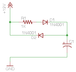
Mmmokay, need to limit the current into the capacitor to charge it, sounds like a series resistor. But need instantaneous power from the capacitor, sounds like a couple of diodes.

Diode / diode-resistor arrangement for slow filter capacitor charge

Diode / diode-resistor arrangement for slow filter capacitor charge, closeup

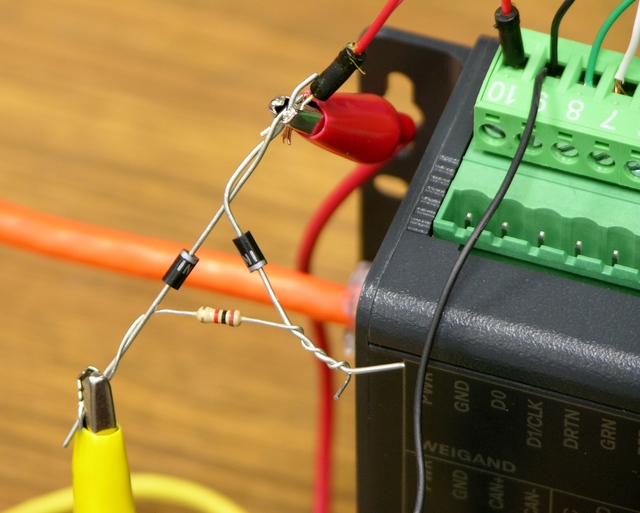
Worked great! I ran a bunch of successful “entries” yesterday afternoon with no more glitches.
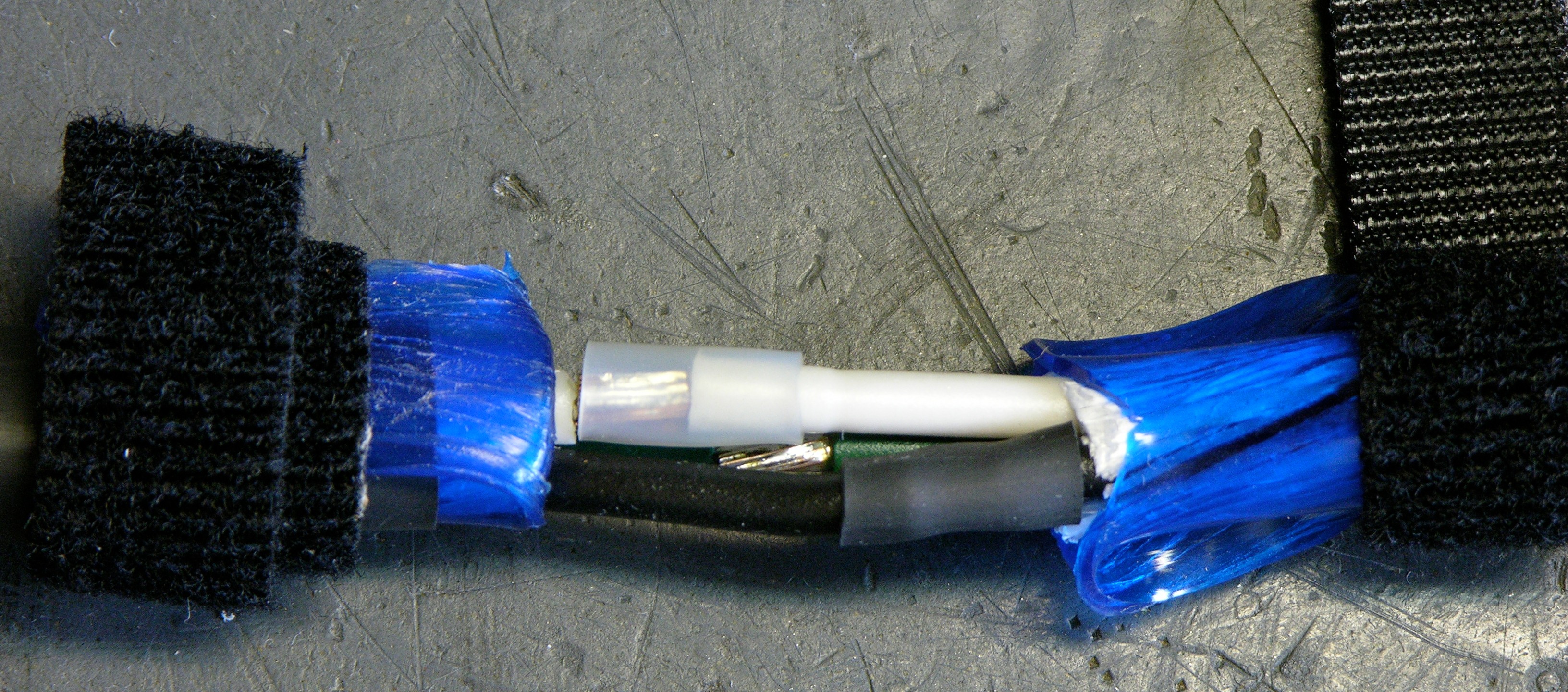
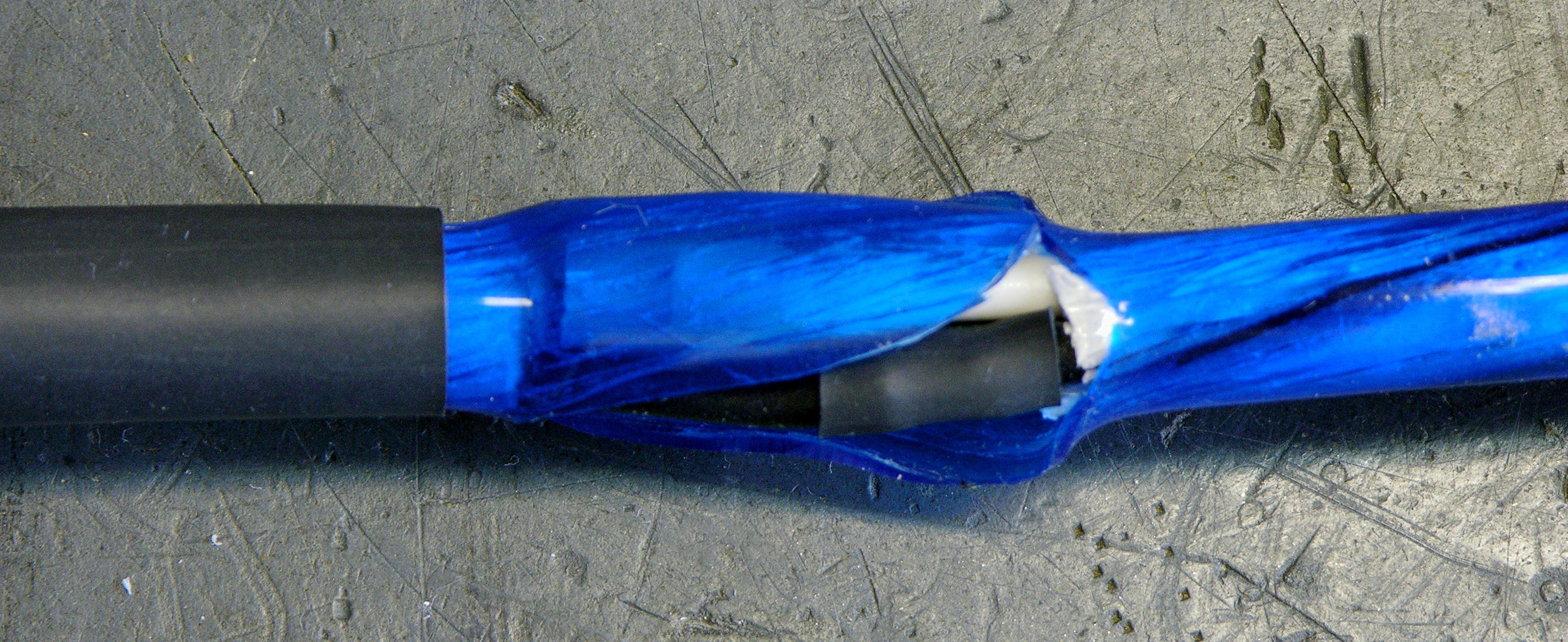
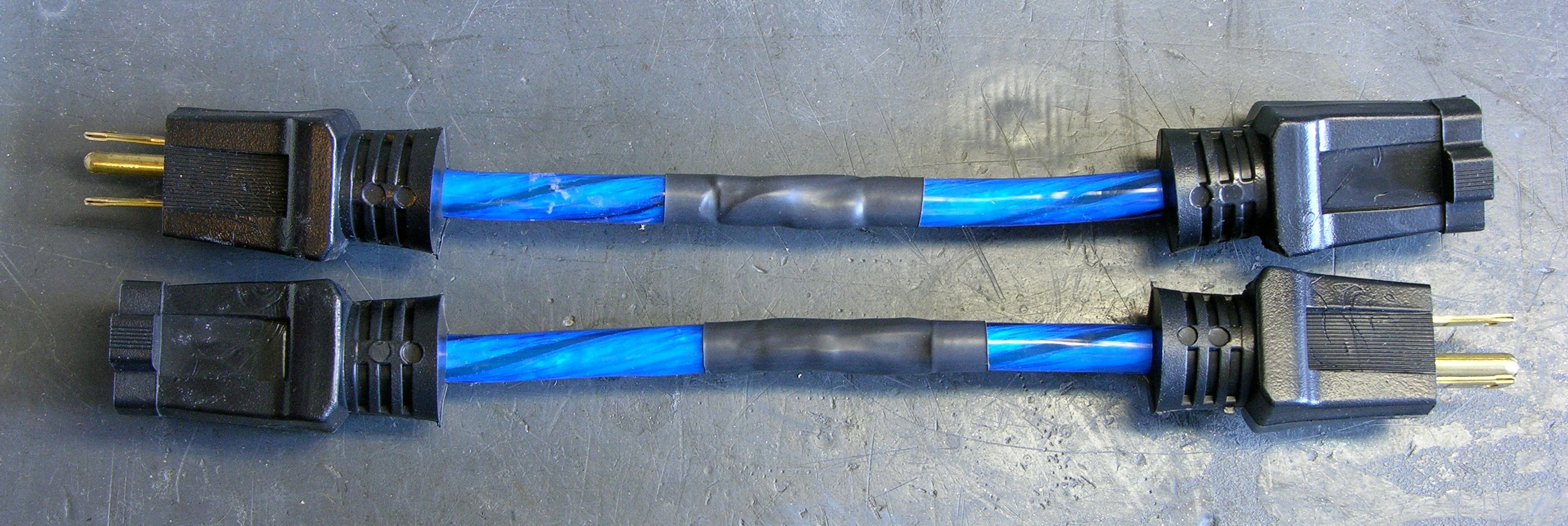
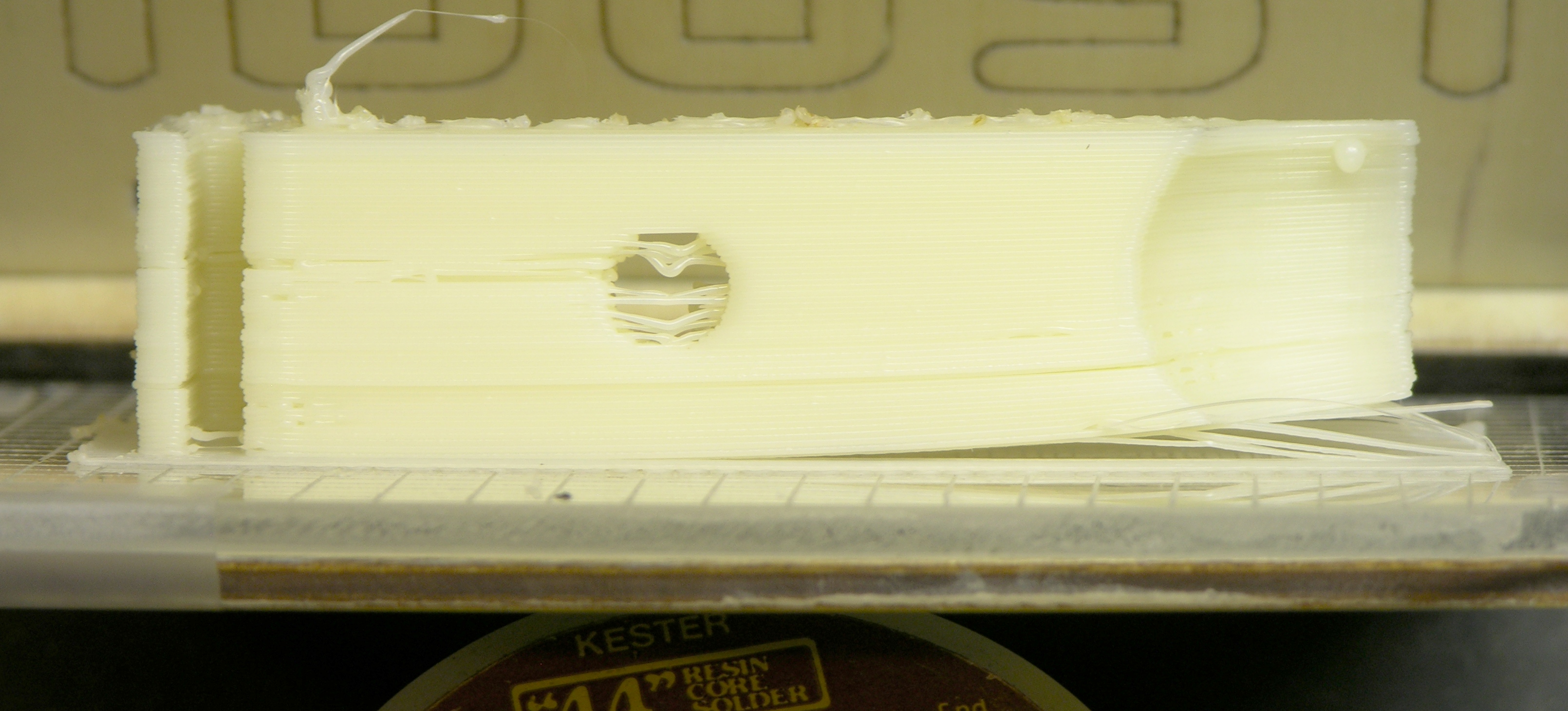
Making More

Filter capacitor with diode / diode-resistor arrangement for slow charge

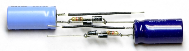
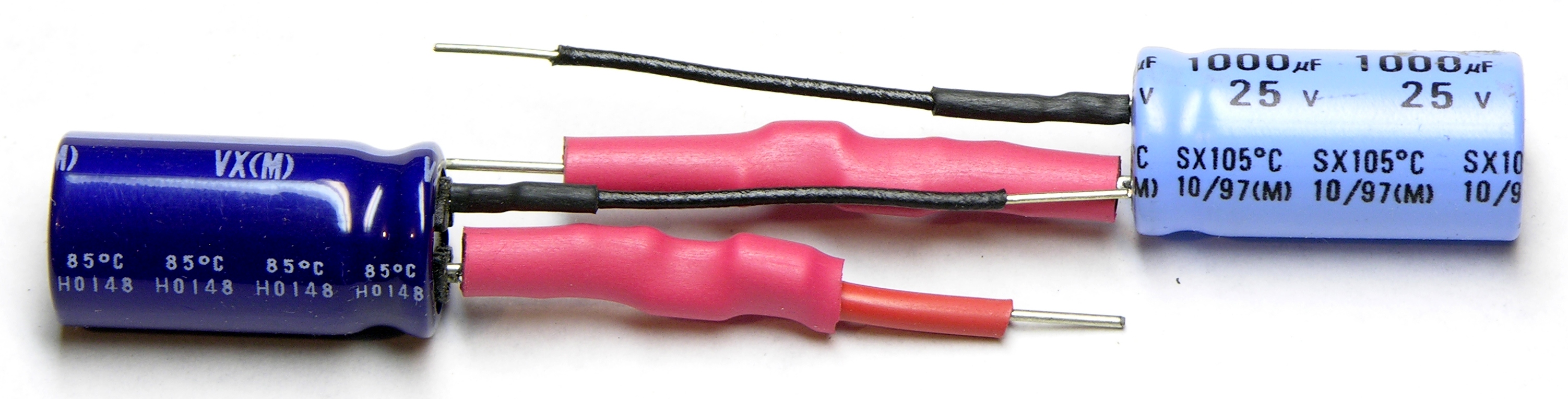
Last night I soldered up a couple to try on some real doors today.

Filter capacitor with diode / diode-resistor arrangement for slow charge, heatshrinked

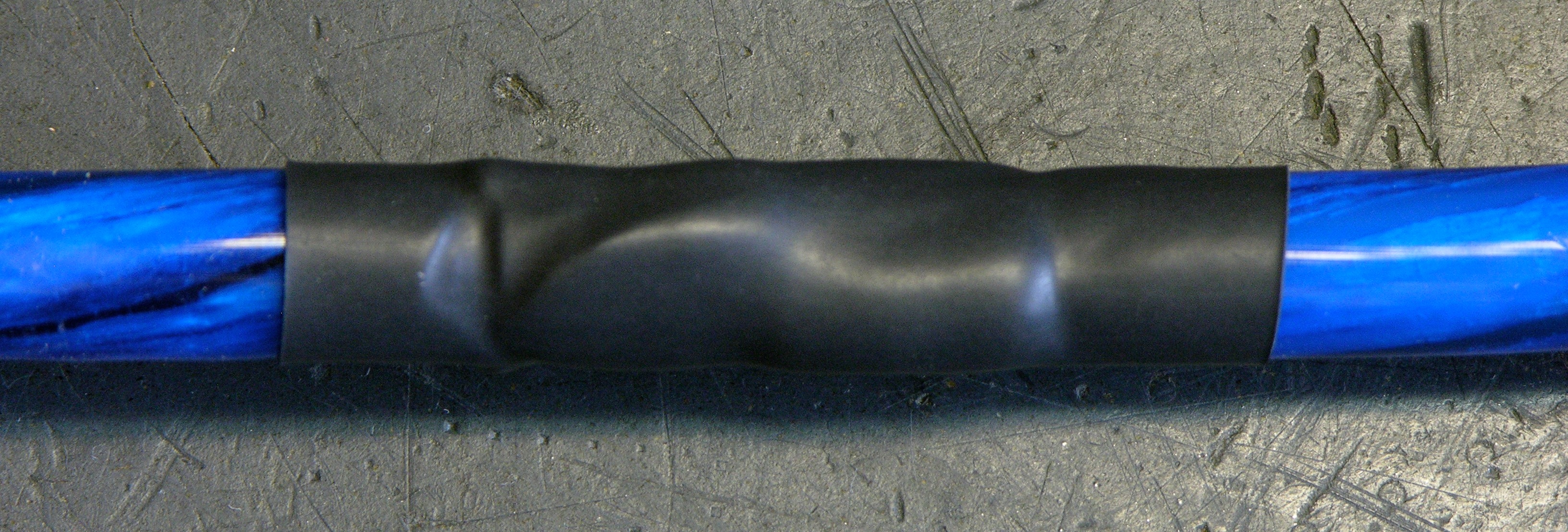
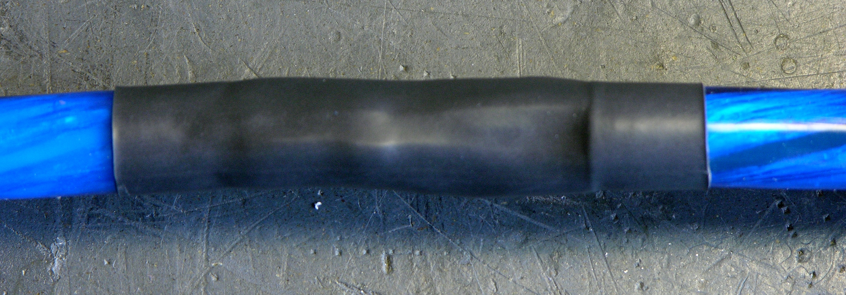
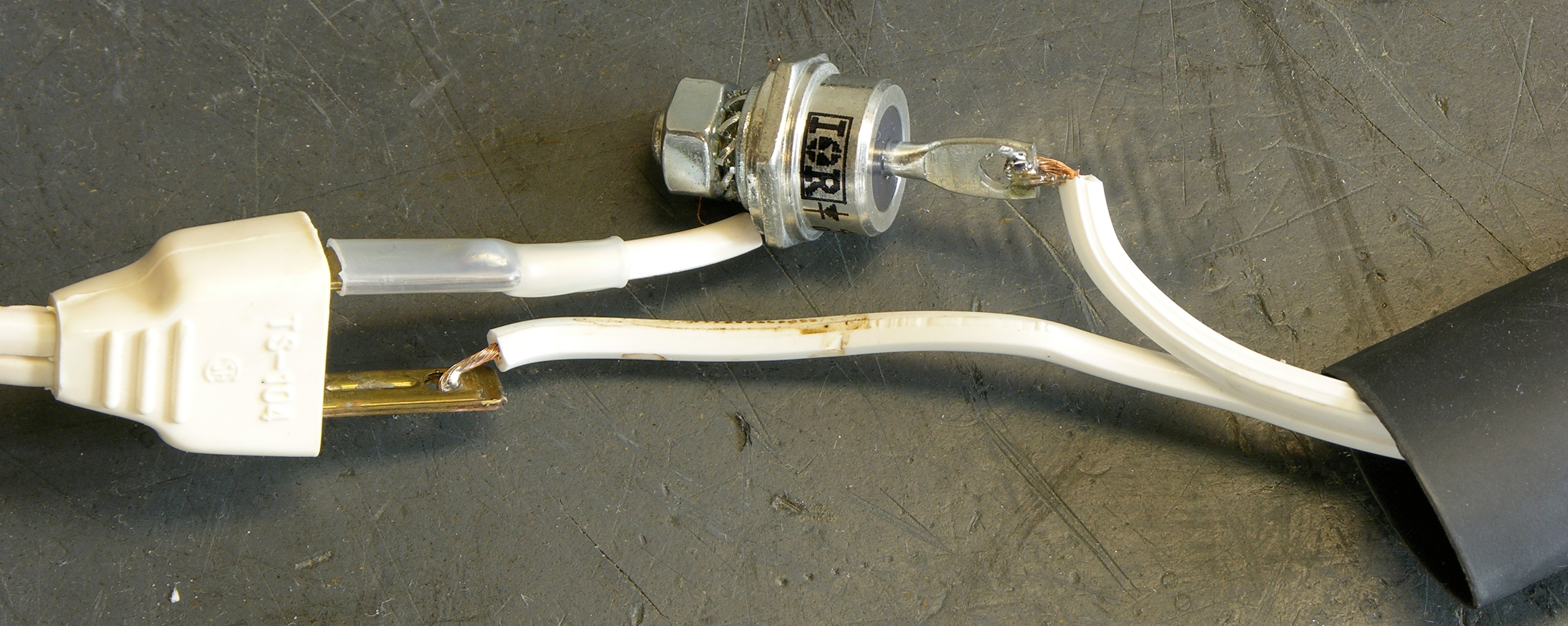
Heatshrinked and ready to go.

Catch Diode

This morning I put one into the bench test setup in place of the loose components I had used yesterday and it worked several times in a row — but one time when the door strike relocked, the whole gateway rebooted.

All righty, we’ll put a catch diode in there yet to shunt the back EMF from the strike coil. Ran a few dozen consecutive simulated entries with no problems. Looks like we’re good.

The contractor is back on site and testing with different strike hold-open times. I’ve explained how to use my capacitor assemblies with extra 1N4001s (reversed), and he’s just added the capacitor and diode to one of the troublesome pilot doors to test in situ. After that we’ll regroup and figure out whether and how to deploy this widely.

As Jeremy would say (approximately), “Science. It works.

Is This Even Reasonable?

Power over Ethernet is supposed to give you 12.95W to use at the device. The only power specification I can find for the gateway says to budget 1.5A for the gateway, which would be at least 18W and already more than PoE delivers.

HES electric door strike, power sticker

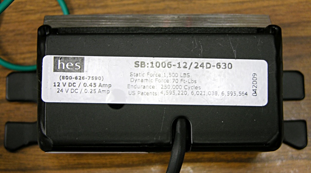
The gateway is supplying about 13V to the reader (and strike). The reader’s datasheet says 90mA maximum average current at 12V, so let’s say 100mA, thus 1.3W. The strike says .45A at 12V, so figure about 5.9W. I don’t have figures for the motion sensor and closure contact, but I expect they’re pretty minimal.

Component Power
gateway 18W
reader 1.3W
strike 5.9W
total 25.2W

And that’s well over the 15W nominal, ~13W delivered that PoE promises — but we already were with just the conservative figures from the gateway.

Going the other way, the reader and strike require 7.2W of the ~13W available, leaving only 5.8W for the gateway at the end of a long cable, or maybe 7.8W for the gateway right next to a power injector on a short cable.

Kind of sounds like it’s not a reasonable expectation and it just happens to work right now, which is a little disappointing. Cutting the strike power in half would make a significant difference — but it’s hard to know whether it would truly be enough to fall within spec without knowing the actual power consumption of the gateway, and these are already brand new, low-power strikes.

I don’t want to install the system and have it work intermittently, nor fail quickly. Sounds like a call to Cisco is in order to see what they think of all this.

Disabling Wireless Transmission on a VR3 Automotive Backup Camera

Sunday, August 2nd, 2009

After backing my bus into my neighbor’s mailbox, I ordered a backup camera from Amazon. The camera touts wired and wireless operation, and I already knew I’d want to use the wired connection for best picture quality.

VR3 backup camera with LCD

Since the Amazon product description for the related VR3 backup camera with 2.5″ LCD says the wireless connection is 2.4GHz and that’s the same frequency band as 802.11b/g, I also knew I’d want to be sure the wireless transmission was inactive so it didn’t interfere with wi-fi reception in the bus. The support document says:

Some of our cameras have the ability to be hardwired to the monitor. This will eliminate interference by completely shutting down the wireless reception.

Which sounded pretty good. All you need is their $20 extension cable … well, no. Their cable is only 25′, and I’ll need about 50′ to get from the back of the bus to the front. Plus I don’t feel like paying $20 each for cables I’d have to chain together when I can just as well build a cable customized to my own liking.

Testing Wired Operation

I was visiting Cort in July anyway, so I took my new camera along for him to help me try out wiring it up and disabling the wireless transmission. As an avid amateur radio operator and repeater maintainer, he’s even better equipped for this than I, and his spectrum analyzer sure came in handy.

(more…)

Reducing Kickback Noise in Soundcraft Spirit E6 Mixer Switching Power Supply

Sunday, April 26th, 2009

Last weekend, I had repaired a Soundcraft mixer switching power supply, but still had switching noise spikes from the transformer primary showing up on the circuit’s ground, and asked whether anyone could suggest how to reduce them or whether they were an artifact of the way I was using the oscilloscope.

Soundcraft Spirit E6 Audio Mixer

Many thanks to everyone who wrote in with ideas! Because of your suggestions, the mixer is now fixed (enough), back together, and ready to go back to the radio lab.

Here were the ideas and their results:

(more…)