Archive for the ‘Equipment’ Category

Q&A: PIC Programmer, Oscilloscope

Saturday, June 19th, 2010

I get very specific questions via my contact form, but also questions about more general issues that might be of interest to a larger audience. I’m going to start posting the latter category here.

PIC Programmer

Trey asks:

Do you have any recommendations regarding a Microchip programmer? There is the PicKit 2 and the Pickit 3. I have read that there are/were issues with the PicKit 3. I know you have used Microchip parts in your designs, but was wondering what your opinion was?

Trey, I’ve never used a PIC that wasn’t already preprogrammed with the LogoChip environment, so I have no experience with PIC programmers.

After reading through PIC and Atmel datasheets in considerable detail to access hardware features on both platforms, my opinion is that I’ll never use a PIC. That’s based on a couple dozen small things that I don’t even remember any more, but which added up to a pretty powerful opinion that Atmel builds a much better thought-out microcontroller that’s much easier to use.

But … that’s not the answer you were looking for. Readers with PIC experience, can you address Trey’s question? Please clearly phrase your responses as statements of opinion (like my opinion above, which is nothing more than an opinion) or as statements of fact with links to supporting information.

Oscilloscope

I am just now starting my journey into electronics and was wondering if you have any recommendations for any particular make/model of oscilloscope?

For someone starting in electronics, before an oscilloscope, I would recommend:

  • A $3 multimeter. I’ve started buying a few of these whenever I go to Harbor Freight and find them on sale, and I give them away like candy. Ace Hardware also sometimes has cheap meters in the dump bin.

    Is this as accurate as a Fluke? Of course not — but for basic electronics troubleshooting, this is more than adequate. The one useful function it lacks is a beeper for continuity testing — you do have to look up at the screen to read low resistance.
  • A breadboard and some components with a list of projects to try. I’d suggest Adafruit’s $50 Arduino budget pack, $65 Arduino starter pack, or $85 Arduino experimentation kit. Even if you’re not that interested in embedded design, the Arduino is a great platform for trying things out and interfacing to the analog electronics, and the Adafruit kits provide a list of experiments to use as a starting point and get the ideas flowing.

But if you’re already doing PIC programming, you seem to be well past the resistors-and-LEDs stage. If you really need a way to visualize signals in order to progress, my oscilloscope recommendation would be whatever working scope you can get for the lowest price, making sure that you do end up with at least one probe (or find a cheap one on eBay).

I paid $25 for an old, used scope about 20 years ago and have only upgraded to a better scope in the last couple of years — which is 20 years old, which I got from a friend of a friend, and which I haven’t put on my bench and started using yet.

The two times I’ve used a different scope are when I found a cheap scope with X-Y inputs that I use for troubleshooting vector arcade game displays, and when I borrowed a digital Tek scope for doing some precise high-frequency measurements.

Granted, I don’t use my scope for calibrating circuits. If you need to do that, you need a better scope, and one that’s calibrated, and that’s going to cost real money. But if visualization is what you’re after, then the cheapest scope that works will do the job.

MIDI Looper?

Monday, May 31st, 2010

I’m starting to think I’d like a MIDI sequencer that behaves somewhat like a looper, doing the following:

  • Capture a short sample of a MIDI performance, including key velocity data.
  • Quantize to a tempo set by a “tap tempo” pedal continually and dynamically throughout the capture, rather than to an LED or click track.
  • Loop and play back, by default to the last tempo seen but honoring continuous “tap tempo” data from the same pedal.

Using a MIDI sequencer with these “tap tempo” features should give greater flexibility for capture and playback during a live ensemble performance than using a traditional audio looper, which requires the whole ensemble to play to the tempo recorded in the loop.

But my real motivation is to be able to play a pattern and then make gradual, multi-bar changes to the analog character of the sound without having to continue playing with one hand and turn knobs with the other.

Record a one-bar pattern on a MIDI keyboard driving a x0xb0x (or a real TB-303, if you’re filthy rich enough to have one and a DIN-sync MIDI adapter to go with it), then play it back and slowly tweak the knobs while everyone else jams on for a bit.

Am I going to find that all of this functionality already exists within the x0xb0x? (It looks like it might be close — MIDI ports; internal sequencer; variable tempo, although perhaps not that sophisticated.) Alternatively, are there MIDI sequencers that do all of this? Is this de rigeuer for every sequencer under the sun?

Calibrating the CupCake Part 1: Nozzle Temperature

Friday, September 11th, 2009

Measuring width of Spam can at grocery store

Last Saturday I went shopping for lunch with a tape measure.

Frying Spam for lunch

Delicious Spam™, fried up nice and crisp and served with Grannie’s “homemade” [what exactly does that word mean?] mustard. Yummmm!

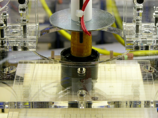
The behavior of my CupCake during the first week of testing and parts-building had made me think that the nozzle was actually colder than the extruder controller believed it was — barely able to push plastic at allegedly 220°C and much happier at 230°C with not much scorching.

MakerBot CupCake plastruder with nozzle in water

I had previously cross-referenced the extruder’s reported temperature with my infrared thermometer’s reading at room temperature (which I no longer trust) and had dipped the heated nozzle into a small pool of water to try to find the boiling point.

Condition Thermometer Measured Thermometer Converted Thermistor Reported
room temperature 68°F 20°C 16°C
dipping nozzle into water and adjusting set temperature until water boils 105°C

In the 100-115°C range, the water would sizzle when the nozzle heater was on and stop boiling when it was off. It boiled most evenly between heating and cooling at a reported 105°C, so I was guessing that it thought 100°C was really 105°C.

This turned out to be incorrect; but it convinced me to perform a more proper thermal calibration, which is what counts.

(more…)

Recommend a Temperature Logger?

Saturday, June 6th, 2009

Any recommendations for a battery-operated two-channel standalone temperature logger that collects data for a while in the field, then uploads via USB or serial to a computer? If proprietary software is required for the upload, then it’s provided? The whole works for under $150?

Insulating Paint for Bus Roofs

I’ve seen a couple of descriptions of mixing ceramic and glass microspheres into paint for repainting bus roofs, with the claim that it’s supposed to have thermal insulating value. One person actually took temperature measurements before and after — but acknowledged that he was going from a schoolbus-yellow roof to white, and the increased albedo obviously helped slow heat absorption into the bus as well.

I have a hard time imagining how — in the paint thickness and mixture proportions described — the microspheres could have much of an insulating effect. It seems as though there must be a whole lot more brittle than peanut, and the heat would go right through the brittle. But I’m willing to be convinced.

The Proposal

Converted schoolbus, front

Let’s do the empirical test of insulating microspheres on a bus roof. Half of my bus roof is already an extremely light grey that looks white. I want to paint it white. I’ll even pre-paint the purple roof edges white for the sake of the test. The magic spheres are relatively inexpensive and I’m willing to try them in the “real” roof paint job.

Help me find a two-channel temperature sensor — or two one-channel sensors — for under $150 and I’ll put one inside and one outside the bus for a month, taking readings every five minutes so we can graph outside and inside temperature. Then I’ll paint the roof with magic spheres mixed in and graph the inside and outside bus temperature for another month and we can compare the two.

Is this a proper test? Care to change the methodology and/or add constraints?

Of Course I Could Build One …

But I have enough things to build right now, I’d rather buy this. ‘Kay?

Soldering My Last Two MakerBot CupCake Stepper Boards

Monday, May 18th, 2009

Over the weekend I received the three missing electrolytics, and yesterday I built the other two stepper driver boards.

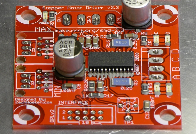
MakerBot CupCake stepper driver board with flowed, half-melted solder paste

Just one noteworthy item — I meticulously lined solder paste on every IC pad, and then during the “soak” period of reflow (also known as “the time it takes my 500W heater to creep the plate up to 185°C”) the paste all slumped together anyway. (Forgive the poor focus in the picture; my camera’s not very good and that’s the best I could get.)

When the solder paste reflowed, surface tension pulled it all into nice little fillets anyway.

Lesson: Don’t bother tracing every IC pad with solder paste; just run a bead perpendicular to the leads and trust surface tension.

Also, I had one solder bridge during reflow. I took a small screwdriver and poked it between the leads, breaking the surface tension and the bridge. Nice trick, and a quicker (and cleaner!) fix than anything you can do after the solder cools.

Assembling the MakerBot CupCake Stepper Controller (or My First Reflow Solder)

Tuesday, May 5th, 2009

Having got my reflow soldering hotplate assembled Sunday, last night I sat down to build the first stepper controller for my CupCake rapid prototyper. Besides being the first of the CupCake’s stepper controllers, this is also the first thing I’ve ever reflow-soldered, EVAR (although not the first SMT I’ve soldered, as I’ve done that by hand before).

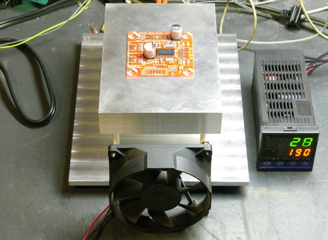
RepRap (MakerBot CupCake) stepper driver on hotplate, assembled and ready to reflow solder paste

There are lots of solder paste and solder reflow tutorials online, and that this ain’t. This is just my observations about parts of the process I hadn’t previously picked up from reading.

(more…)

Copycat PID-Controlled Solder Hotplate

Monday, May 4th, 2009

In early February, a correspondent pointed me to Jeff Keyzer’s mightyOhm blog. I immediately ran across his homebrew PID-controlled soldering hotplate and improvements, and immediately knew I had to have one.

I contacted Jeff through his blog and he was great about sharing his knowledge. He’d built his hotplate using the last of some surplus parts he’d picked up at a now-closed store in the Valley and was considering ordering a batch of parts to make a few for all the folks inquiring about them, but hadn’t done so yet. I was eager, decided it’d be quicker to make my own (and three months later, that may actually have been correct), and went off to eBay to find myself some parts. I also bought aluminum and took a practice run at polishing it.

Most of the CupCake PC boards are SMT; and although I’m very comfortable soldering SMT by hand, I really wanted to get my hotplate up and running and use the CupCake boards as a chance to try out reflow soldering. (That’s why I started by assembling the opto endstop boards, which are the only all-through-hole boards in the kit.)

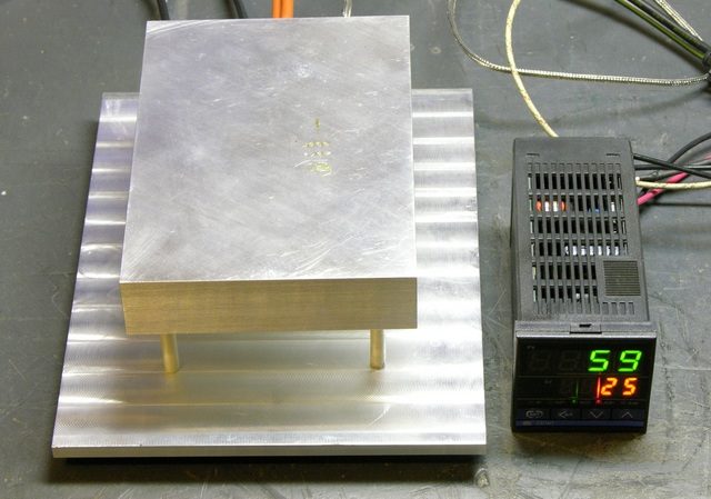
PID-controlled SMT soldering hotplate

So last night I got a working proof-of concept hotplate going, and tonight I can start on the CupCake SMT boards. W00T!

Here’s the tale of how to build a copycat PID-controlled hotplate, with a digression into how lucky I got buying exactly the right PID controller with no idea what I was doing.

(more…)

Refurbishing My Isolation Transformer

Thursday, April 30th, 2009

An isolation transformer, as used in electronics testing and repair, is a line-powered transformer with 1:1 windings (e.g. in the US, ~110VAC in, ~110VAC out). It’s used to isolate a circuit under test from line power for two main reasons (that I know of):

  • With line-powered equipment, if you were to touch a hot part of the AC side of the circuit while it was plugged straight into wall power, you could become a return path to ground and get electrocuted.

    The transformer isolates it from the rest of the world, so your risk is reduced to becoming a return path within the circuit, and you’re not at risk of conducting from any single point to ground. This doesn’t eliminate the need for care, but it reduces the hazard.

  • Some line-powered circuits use a local ground that is something other than earth. (The mixer power supply I repaired recently uses a local ground on its primary side that’s at about -85VDC with respect to earth.)

    If you want to use test equipment (oscilloscope, line-powered meter, etc.) to probe the circuit, you need to connect the equipment’s ground to the circuit’s ground. If they’re both line-powered and the circuit uses something other than earth as ground and you connect the equipment’s real-earth-ground to the circuit’s specifically-non-earth-”ground,” you’ll create a short circuit fatal to one or both pieces of equipment.

    The isolation transformer “floats” the circuit so its local ground is safe to connect to your test equipment’s ground. Of course, this potentially reintroduces the shock-to-earth hazard mentioned above, during the time you have the grounds connected for testing.

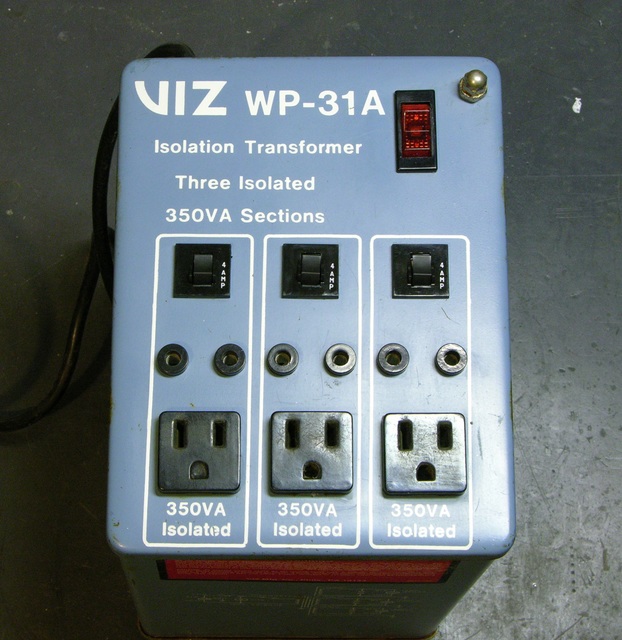
Viz WP-31A isolation transformer with carrying handles removed

While repairing the aforementioned power supply, I dug my isolation transformer out of the basement. I had acquired it grungy and broken (and this is odd, but I don’t remember whether I got it from Slim or purchased it at Lloyd’s) and it had been through a basement flood, so it needed rework before I could use it. I’ve just polished off the last of the repairs.

(more…)

Polishing Aluminum: Practice Run

Sunday, February 22nd, 2009

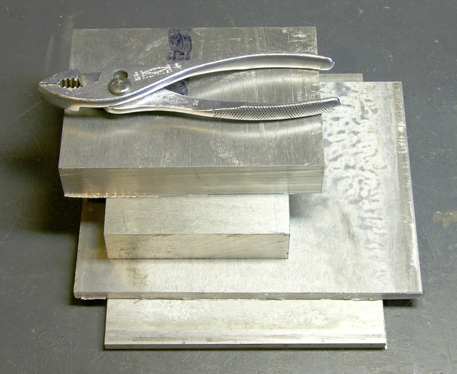
Last weekend I picked up some aluminum block at The Yard, an aircraft (and miscellaneous) surplus and supply store in Wichita, for an upcoming project. I also picked up aluminum polishing supplies at Autozone based on the experienced recommendation of the shift manager with a very shiny motorcycle outside.

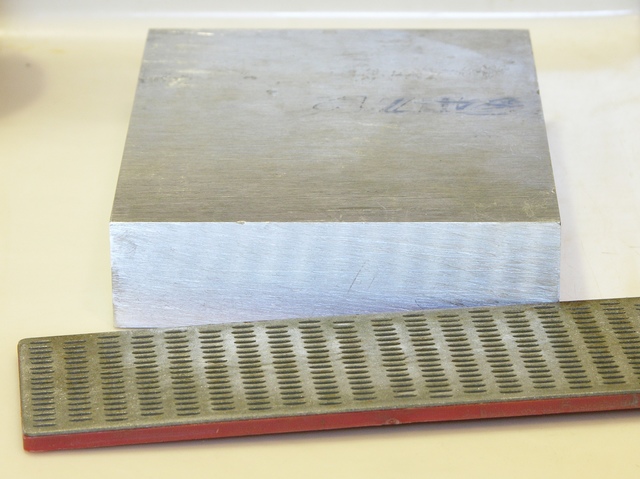
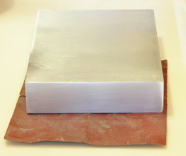
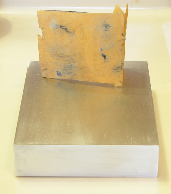
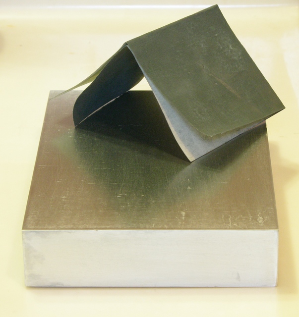
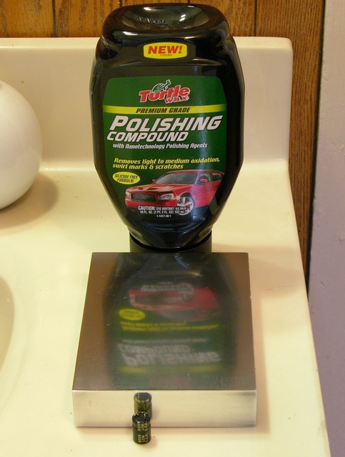
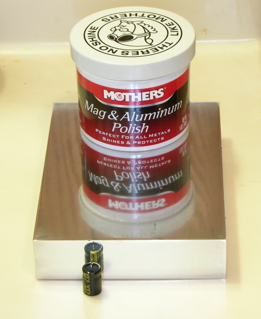
Here’s a first pass at cleaning and polishing a block using materials I had around the house. The polished surfaces really highlight which stages of sanding needed more work — at a minimum, not skipping from 220 to 600 grit (I don’t seem to have any 400) and continuing up to 1500 — which was largely the point of this test. No need to point out my errors; I already know.

Tomorrow night I’m having supper at a machinist’s house, and I hope he may be able to do some surface cleanup for me before I redo this block and tackle the other three.

Aluminum blocks and plates

Aluminum block, end honed with diamond file

Aluminum block, face sanded with 180 grit

Aluminum block, face sanded with 220 grit

Aluminum block, face and end sanded with 660 grit

Aluminum block polished with Turtle Wax Polishing Compound

Aluminum block polished with Mothers Mag & Aluminum Polish

And by the way, the Mothers polish has a smell like vaguely lime-scented floor cleaner that takes me straight back to a Colorado Springs Popeye’s Chicken restaurant on vacation in the late 1970s. Smell is the sense with the strongest link to memory.

Cleaning (and Cleaning . . . and Cleaning) Akai Headrush E2

Wednesday, December 31st, 2008

I just bought an Akai Headrush E2 delay and looping effects pedal. It’s the box that the amazing KT Tunstall uses in her solo performances of “Black Horse and the Cherry Tree” to lay down her own rhythm and backing vocals before playing guitar and singing, all by herself. It’s a really slick setup.

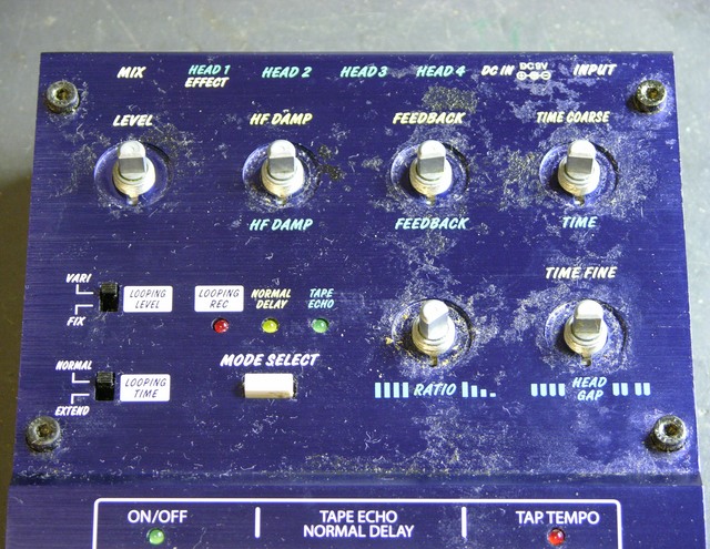
Filthy Akai Headrush E2 Delay/Loop controller

I got a great deal on eBay — they retail for ~$200 and typically run about $150 on eBay, but I picked mine up for $76 missing the 9V power supply. It turned out to be an even better deal than I imagined, because the seller forgot to mention that the pedal came with a generous helping of organic matter, lovingly applied all over the pedal. This picture is after a preliminary 3x cleaning with Goo-Gone.

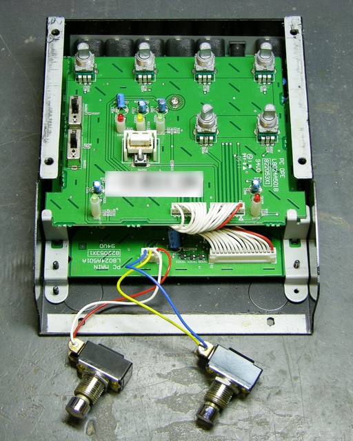
Not only was the case unsightly, but the foot switch action was dodgy as well, and that’s not easily cleaned from the outside. To really get the case clean, I wanted to get the panel loose of the controls so I could give it a good soak; to fix the buttons, I wanted to spray them with contact cleaner. I figured I may as well show off the inside while I had it open anyway.

Akai Headrush E2 Delay/Loop controller upper PC board

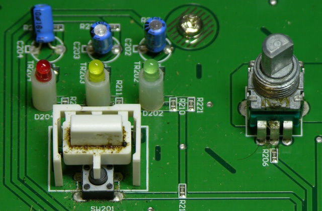
There’s the upper PC board. Note the filth that crept down onto the mode select pushbutton, and even the potentiometers:

Filthy Akai Headrush E2 Delay/Loop controller pushbutton

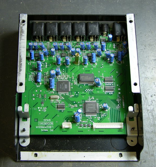
I had already got the outside of the lower case fairly clean, but wanted to clean the inside as well, so I went ahead and took both boards out. Here’s the lower PCB, where all the magic happens:

Akai Headrush E2 Delay/Loop controller lower PC board

I actually had a plan for dealing with the filth. Goo-Gone is great at softening and removing sticky adhesives like the remains of the world’s largest velcro strip the former owner had attached to the bottom of the pedal; but there’s no cleaner like Fantastik for removing the evils that men have done from arcade game control panels and (apparently) guitar/keyboard effects boxes.

I gave the top case about a ten-minute soak in Fantastik — I had already soaked and scrubbed in Goo-Gone three times, mind — and after the soak it literally rinsed completely clean under the faucet, with the tiny exception of a little bit of gunk still in one of the potentiometer mounting recesses. The foot switches left behind a pool of brown liquid (and I had only sprayed the mounting threads), the potentiometer knobs had white inset lines again, and the washers that I’d had to pry loose of the case with my knife were clean and shiny.

I also used an “acid brush” (dry, no cleaner) to knock the accumulated dust and grit loose of the PC boards around the base of every component that penetrates the top cover and get the boards nice and clean again.

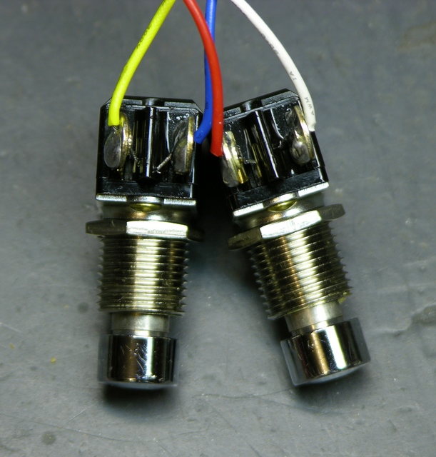
The pushbutton foot switches aren’t quite sealed, and I was pretty sure I could see in to the inside along the solder lugs. I sprayed with wiper cleaner/lubricant, worked the switches a bunch of times, and repeated the spray/work process twice more. Shiny!

Akai Headrush E2 Delay/Loop controller pushbutton foot switches, cleaned

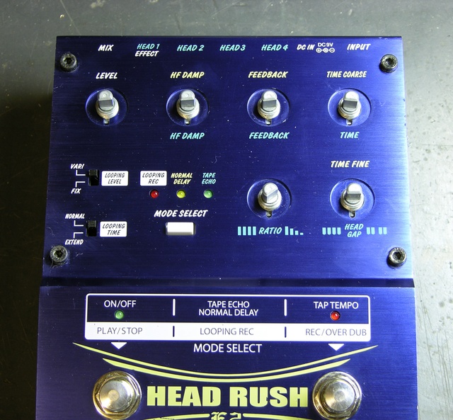
Same pedal reassembled about an hour later, with towel lint added for your viewing pleasure.

Akai Headrush E2 Delay/Loop controller, cleaned

And remember, folks, you can’t go around calling yourself anal-retentive if you don’t bother to align your fasteners.

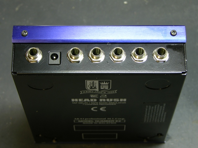
Akai Headrush E2 Delay/Loop controller rear panel

The pedal now works perfectly — no more double-taps from switch bounce and missed taps from stickiness, etc.

It makes such a difference that before cleaning, I couldn’t understand the operating instructions (because the pedal didn’t seem to be doing what they seemed to be saying), and afterward they’re much more clear (although incomplete in failing to mention that it does not record while you’re tapping the tempo in delay mode, pity; and confusing, incomplete, and inaccurate in their description of looping mode operation; but who, bitter, me?).

Seriously, after an order of magnitude shorter time poking around than I had already done before cleaning, I feel pretty comfortable that I understand how to get it to do the things I want to do. Using the delay mode, I can now play a pretty passable rendition of the “Fly Like an Eagle” synthesizer intro. Wonder what to tackle next . . .