Archive for the ‘3D Printing’ Category

Voron 2.4 Build — Fysetc Spider MB Test Firmware

Sunday, August 21st, 2022

Voron 2.4 LCD showing Fysetc Spider mainboard Marlin test firmware boot

I still have notes to share about the rest of the mechanical assembly and I have so many thoughts about the wiring; but I just powered up the Voron to test the mainboard and want to record my thoughts while they’re fresh.

No, my Voron won’t run Marlin; but the test firmware does.

(more…)

Random Weekend CAD and Printing

Sunday, June 19th, 2022

3D-printed funnel, solid-state relay safety cover, ethernet cable holder

Musing on Nozzle Height Above Build Surface

Monday, June 13th, 2022

Graph speculating about 3D printer first-layer adhesion

I’d always assumed that lowering a 3D printer’s nozzle closer to the build surface causes the extrusion to stick better and better until it’s pressing hard enough, at which point the stickiness asymptotically approaches maximum; and of course once there’s no space left between the nozzle and build surface, one can no longer be said to be sticking filament to the surface.

Thus if a particular filament sticks well to a particular surface, optimize for the best appearance — first layer nicely joined with no roughness from overextrusion nor from the nozzle troughing the filament it’s laying down. If a filament doesn’t stick well to a surface, lower the nozzle until it does; and no need to fine-tune for adhesion — overshooting will only hurt the appearance, not adhesion.

Graph speculating about 3D printer first-layer adhesion

My friend Cort has started to convince me of a different model — that pressing the filament too hard makes it stick less well, whether through an action similar to tiddlywinking your way along the length of a rubber gasket lying on a workbench or by some other phenomenon.

In this model, driving the nozzle too close to the build surface is self-defeating and to get a troublesome filament to stick, one should lower the nozzle very carefully in fine steps to avoid overshooting the peak of the adhesion curve. Cort’s patient tuning this past weekend of one of my Enders on which I could no longer get anything to stick bears that out.

Graph speculating about 3D printer first-layer adhesion

Of course, with some filaments and slicer profiles, the graph looks more like this — peak adhesion isn’t actually good, at best kinda good.

More on this topic soon.

Voron 2.4 Build — Actual AB Motor Orientation

Wednesday, June 1st, 2022

So actually the AB stepper motors need to be installed with their connectors facing each other, toward the center of the back plane of the printer. The 2.4r1 instructions don’t mention this at all; the 2.4r2 instructions mention it clearly.

Voron 2.4 3D printer B block

If you installed them with the connectors facing out the back, especially if you did that based on my earlier and now corrected misinformation, be apprised that you can correct them merely by loosening the AB belt tensioners on the front of the printer, removing the three long M3 screws that go all the way through each of the blocks into the steppers, rotating the steppers in place, and reassembling.

If you know someone who’s a dope and already took the top off of the A or B block, spilling precious towers of bearings and washers, let them know that it’s even easy to recover from that. Remove both AB steppers from their blocks to get lots of slack in both belts; hold long M4 machine screws up from below through the bearing positions and rebuild the towers; nudge the belts out of the way of plastic parts; put the lid back on; and push the M5 machine screws down through the bearing stacks, pushing the temporary M4s out of the way as you go. I mean as they go.

Voron 2.4 Build — Mains Power Panel

Monday, May 30th, 2022

Two styles of Voron 2.4 mains power panels

The 2.4r1 assembly manual only shows assembly for the plug_panel_filtered_mains.stl (lower), which is what I printed while waiting for my kit to ship with the power inlet that fits the plug_panel.stl (upper). Don’t be fooled like me.

Mains power panel with switch removed

On the subject of the power inlet … the default configuration puts the power switch oriented with off up and on down, which I cannot abide. A small prying tool on the switch’s latches frees it from the inlet housing to be reinstalled in the One True Orientation. Just take a snapshot of the power wiring on your switch before undertaking such shenanigans.

Voron 2.4 Build — Printhead Assembly

Monday, May 30th, 2022

A few notes on assembling the printhead:

The 2.4r2 assembly manual has much more detail than the 2.4r1, very much appreciated.

Even the 2.4r2 manual leaves it to you to figure out how to assemble whatever hot end you have. Because my kit came with an E3D-v6 clone hot end, I found these self-proclaimed outdated E3D-v6 assembly instructions that direct you to better-maintained instructions that no longer exist, and followed the link within these instructions to another set for installing the old-style thermistor.

Voron 2.4 printhead without fans

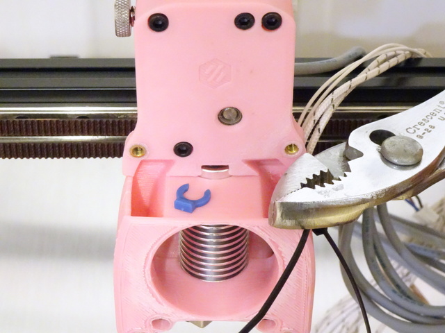
The 2.4r2 instructions and their diagrams don’t speak to this detail, but later assembly makes it clear that one does leave the (here black and barely visible) plastic ring that guides the PTFE tube into the cold end but one omits the (here blue) clip that in some uses locks the ring onto the PTFE tube.

After measuring and marking the PTFE tube length, I should have cut it with my PTFE tubing cutter but I was impatient and cut it with diagonal cutters, then mashed it round again. I look forward to regretting that later.

I’ve completed the printhead assembly and have yet to figure out what is meant by this instruction when mounting the hot end to the X carriage:
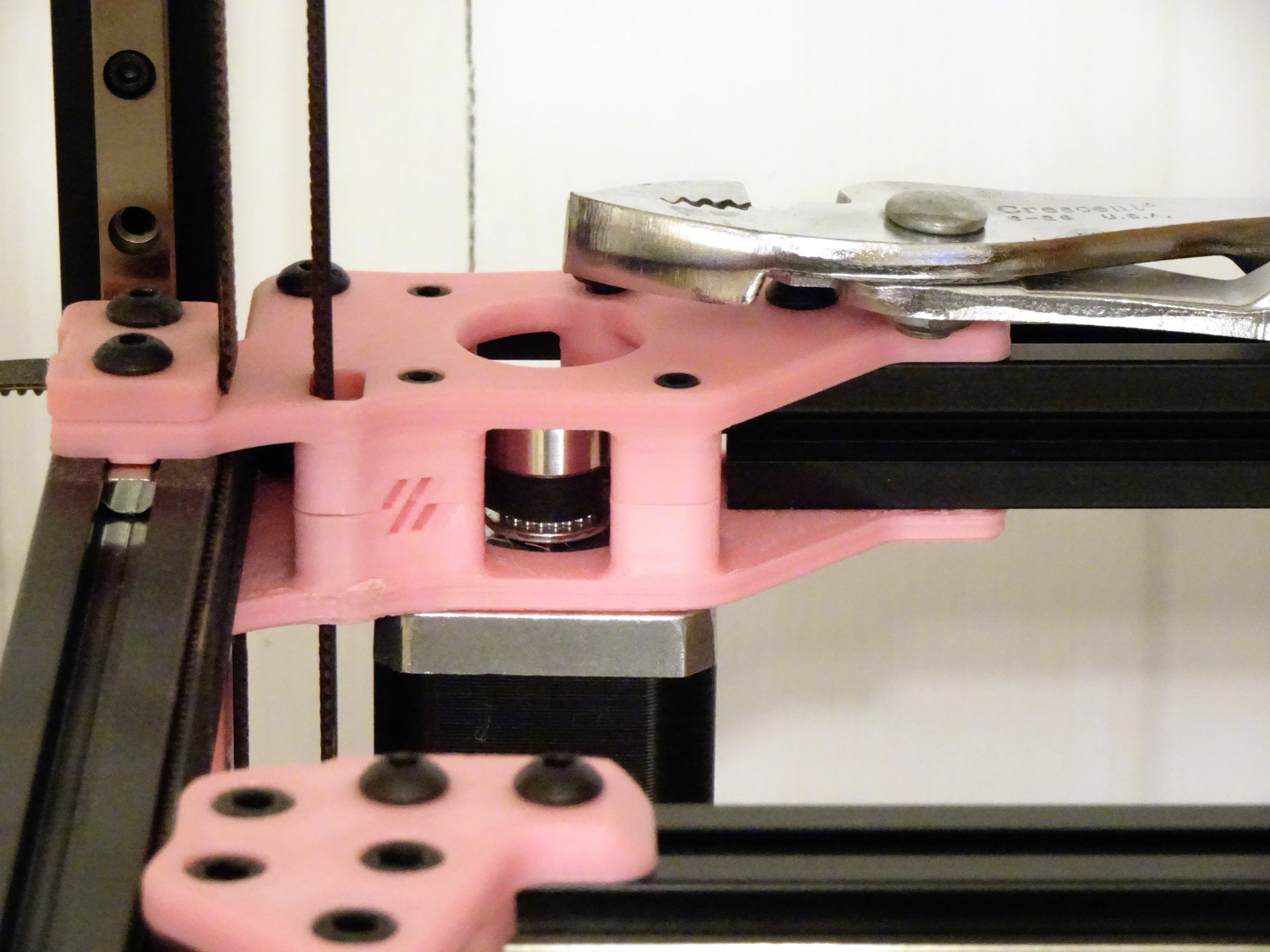
INDEXING BOLTS
The bolts are used to index the tool cartridge. Leave them slightly loose so that the cartridge can be slid out.

The 2.4r1 instructions make no mention of where the pinion gear should be positioned on the motor shaft. The 2.4r2 instructions give a dimension and also appear to show a printable shim that will position it correctly, which is a fantastic idea (though I didn’t download the STLs and print it myself).

Voron 2.4 clockwork filament motor assembly

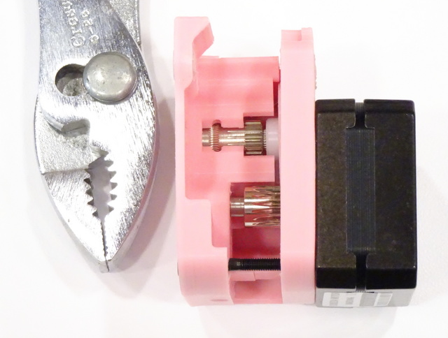
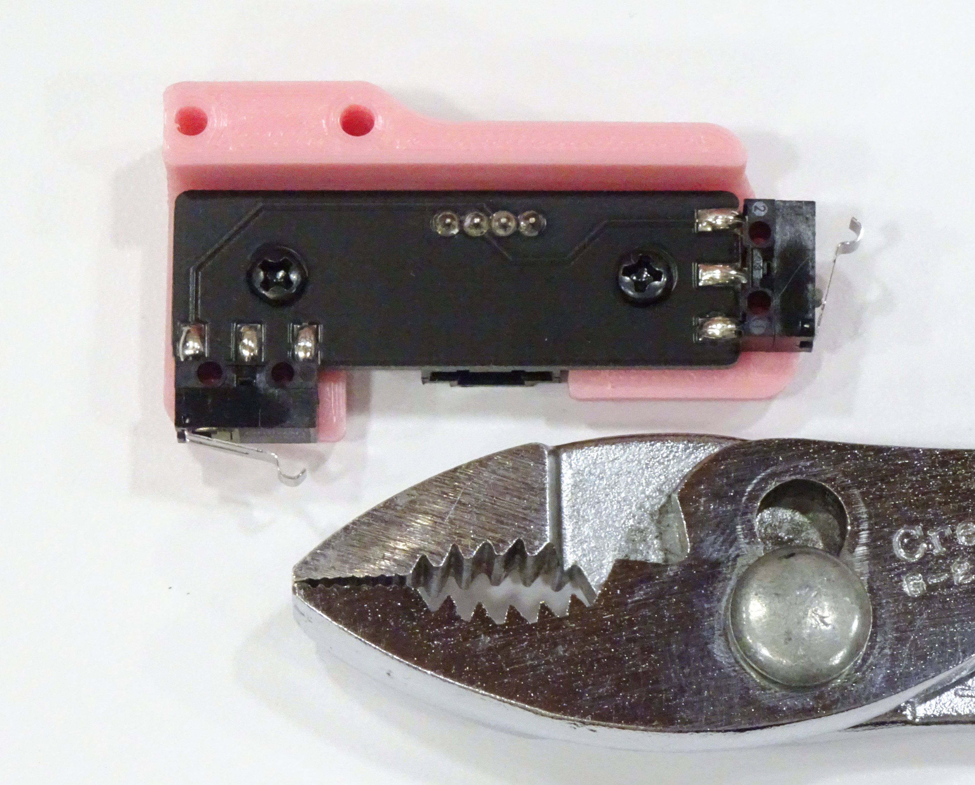
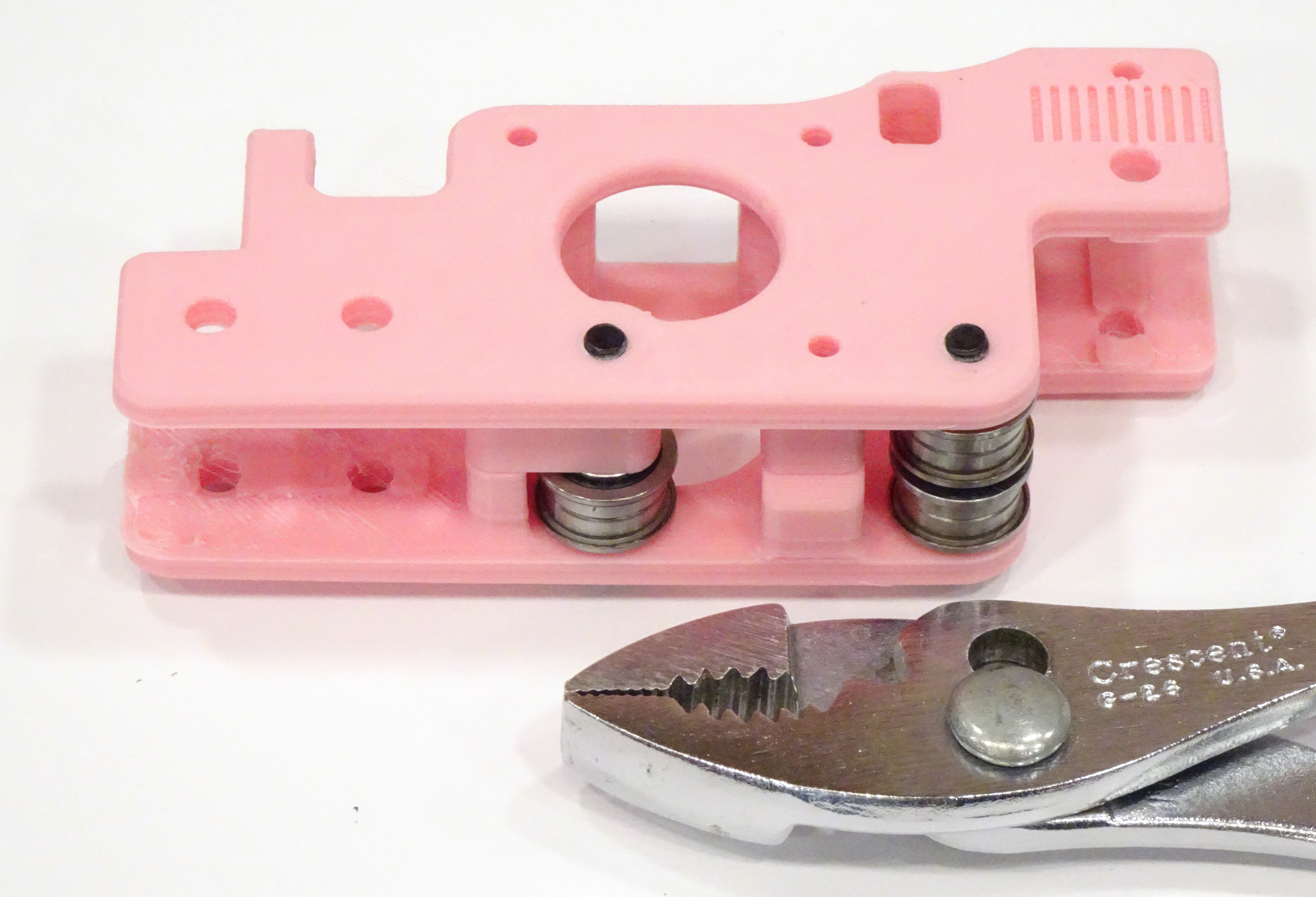
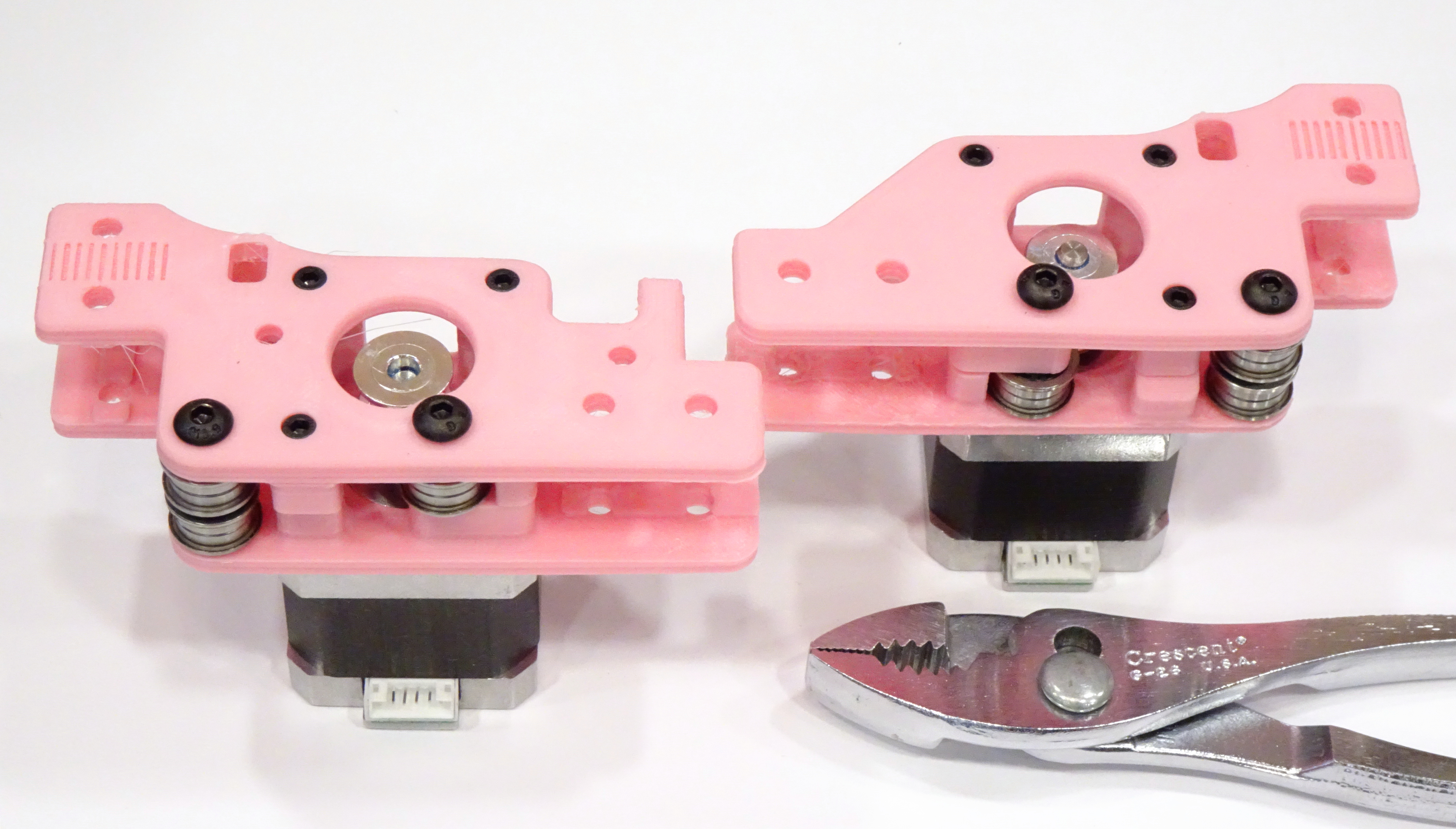
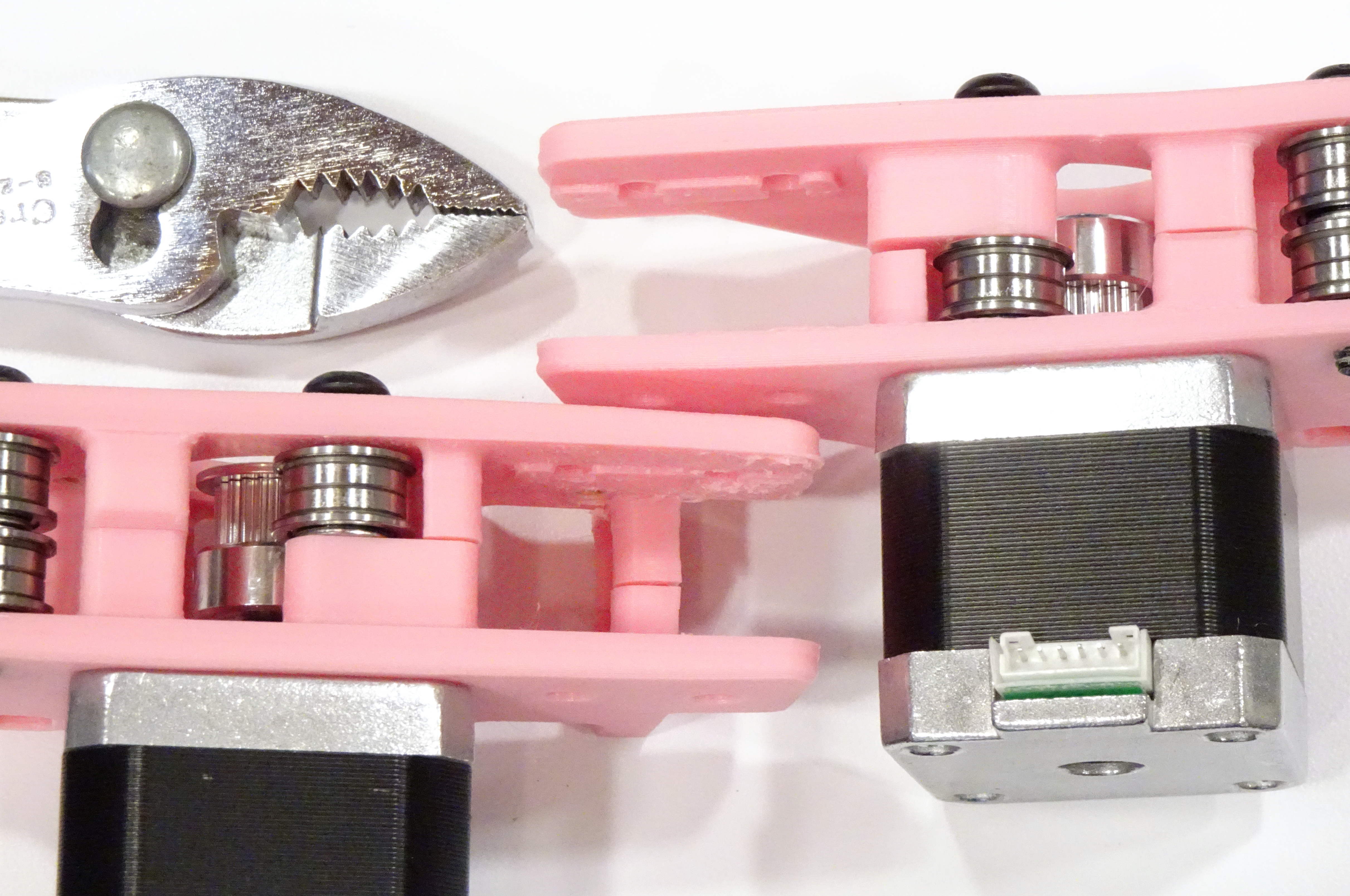
The white nylon drive gear in my Fysetc kit wasn’t installed fully into position at the factory; you can see a bit of splined shaft between the hub of the nylon gear and the Bondtech-style filament gear; and you can see that the filament groove is misaligned between the Bondtech-style gear and the housing. I took it back out, supported the back end of the nylon gear with a large nut, and pressed it the rest of the way into position in a bench vise.

Voron 2.4 part-cooling fan with broken wire

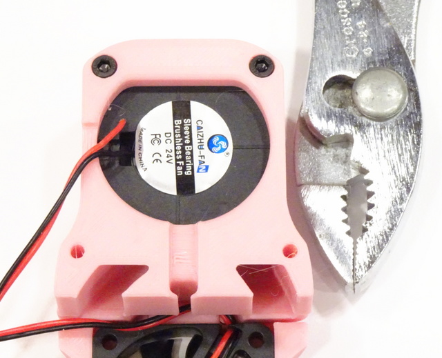
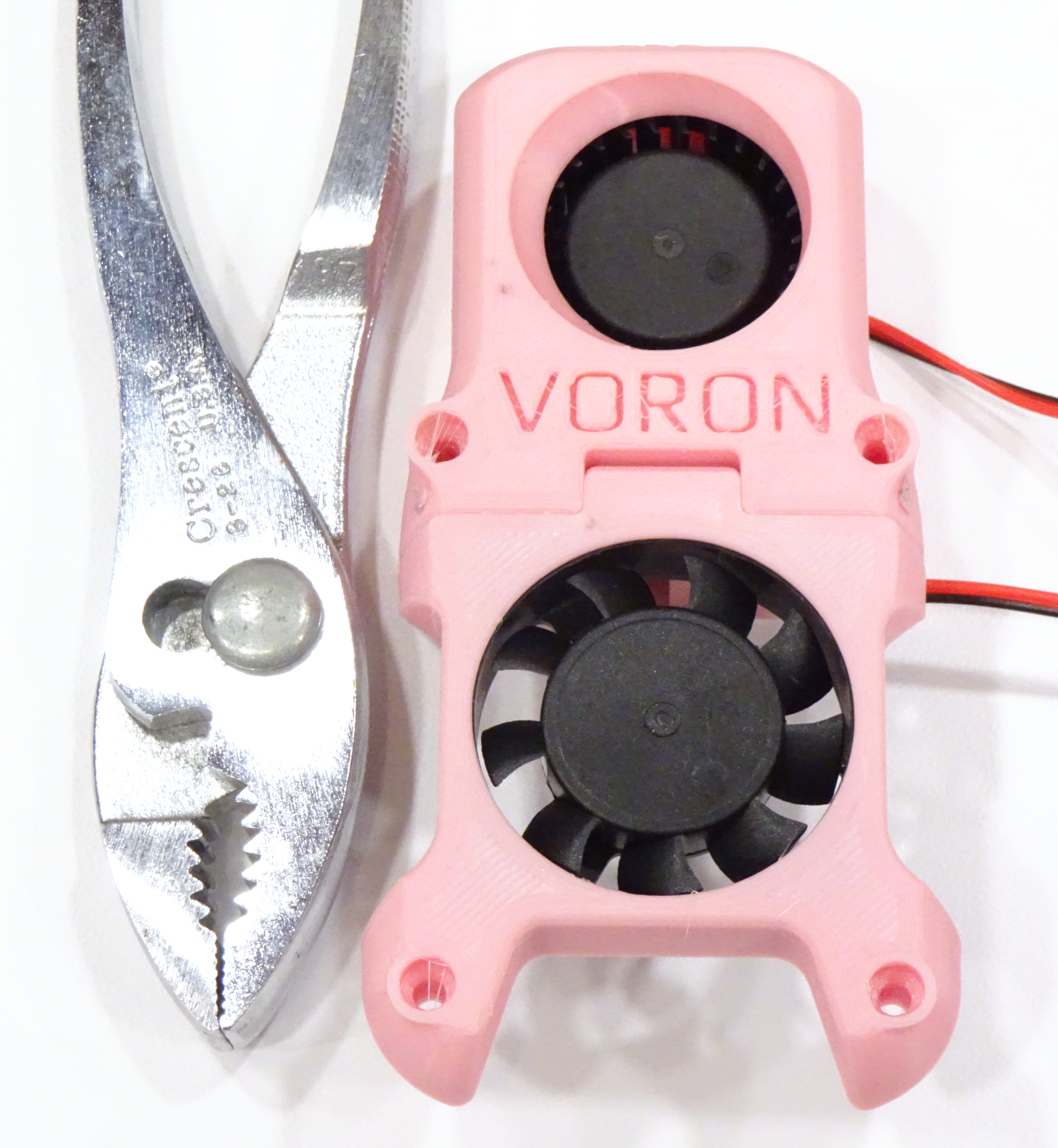
There’s just barely room between the 4020 blower fan and the printed housing to leave the fan wires routed through their factory strain relief, differently than shown here. You should do that. So you don’t break off the fan wires. Like I did. And have to solder one back on.

After reattaching and routing the wires back through the strain relief, I covered the solder joints with hot glue to provide extra strain relief. I did note first that the black surface immediately beneath the wires is the fan and that it’s probably counterproductive to fill the whole cavity with glue.

Since I’d removed the sticker to have a teence more room to solder, I added a couple of drops of lightweight oil to the fan shaft before closing things back up.

Voron 2.4 fan assembly

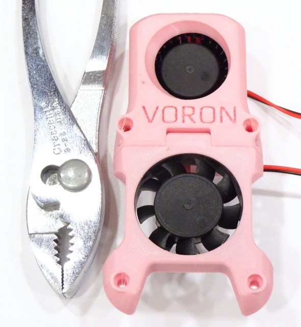
The instructions and diagrams are hard to read regarding the orientation of the (lower) 4010 fan; but sticker-side-in blows air onto the cold end rather than sucking air past it, and more importantly, looks better.

Voron 2.4 afterburner printhead with cable ties

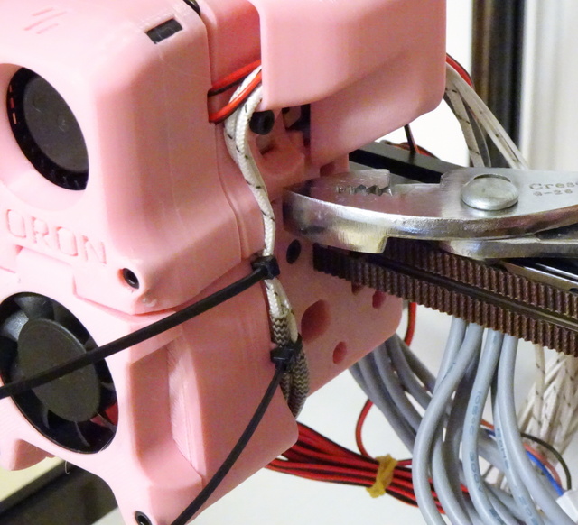
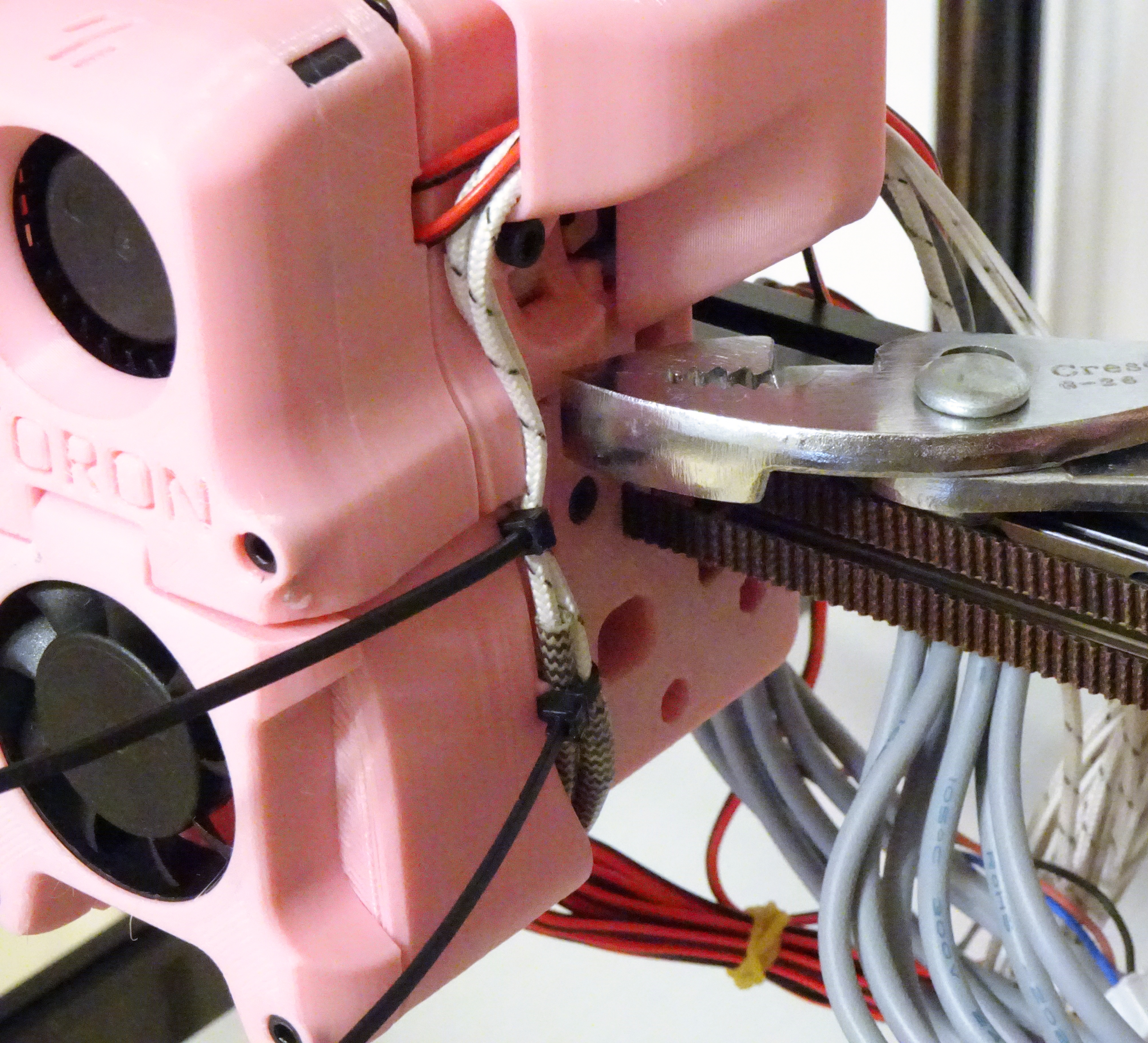
I presume the little notches in the toolhead housing are for cable ties (which I have since trimmed).

Voron 2.4 Build — AB Belts

Friday, May 27th, 2022

I took a break from Voron assembly last November due to being quite vexed at crucial information omitted from the assembly manual and the extra effort in interpretation and rework it caused me.

With a little one on the way [that is, I just ordered a Voron 0.1 parts kit], I figured it was time to get the 2.4 assembly finished; and thankfully, since November the assembly manual has been overhauled from r1 to r2 and is much, much, much better. If you’re assembling a Voron 2.4 and you don’t already have the r2 assembly manual, go download it right now. You can thank me later.

Voron 2.4 AB belt drive

Before my hibernation, I had assembled and installed the gantry. All of my frustrations about the instructions that drove me away at the time have now been addressed, save one, presented here for your sanity:

The instructions say to route the AB belts by clamping one end onto the carriage, then threading them through the entire gantry, then clamping the second end onto the carriage. I tried that at least twice and found it difficult each time to fish the belt ends through the AB blocks in the back corners. It was much easier for me to start in the middle by pushing both ends of each belt through this opening and around their drive pulleys, then threading the belts outward toward both ends.

As I resume assembly, I’ll compare 2.4r1 and 2.4r2 instructions, only calling out issues with the r2 instructions.

Voron 2.4 Build — Fysetc Custom Parts

Friday, November 26th, 2021

Fysetc drag chain for Voron 2.4 3D printer

At the time I purchased my kit and at the time I printed my parts, the Fysetc bill of materials for the Voron 2.4 kit listed the specific part number of Igus drag chain, so I printed the Igus chain anchors (upper right) from the Voron parts repository. The chain that shipped clearly doesn’t fit those anchors; so I’ve now printed the generic chain anchors (lower left) from the repository, which I see I positioned for the photo 180° from their proper orientation.

I don’t mind at all when a kit assembler makes equivalent or better substitutions from the original BoM. I do mind when they state or imply that they’re providing one part and they provide another.

Voron 2.4 X-Y limit switch assemblies

Case in point about not minding a substitution, Fysetc clearly calls out that they’ve provided an X-Y limit switch PCB accepting a single cable rather than separate limit switches requiring soldering and DIY cable; and they provided a link to a new limit switch mount to use with it (lower). I’d already printed the mount for separate limit switches (upper) before noticing this; no big deal.

Fysetc X-Y limit switch module for Voron 2.4 3D printer, component side

Assembled, it’s sleek and cute.

Fysetc X-Y limit switch module for Voron 2.4 3D printer, solder side

It does differ from most of the Voron assembly in that it looks to me like it’s made to be installed with flat- or oval-head screws (countersunk on the back side of the head) and there are none in the kit. I made do with M3 sheet metal screws, which are loose in the PCB holes but cinch it down fine when tightened; but for someone who doesn’t have a supply on hand, this could cause an extra trip to the hardware store.

Voron 2.4 Build — AB Blocks

Thursday, November 25th, 2021

The Voron 2.4 has a “CoreXY” drive system, meaning instead of having one axis’s stepper on a gantry moved by another axis’s stepper, it has two steppers in the back corners connecting across the Y rails and the X gantry to the printhead with a complicated routing of two belts, to reduce mass of the gantry and facilitate higher acceleration. Turning a single stepper would move the gantry diagonally; so the two steppers work together to perform Cartesian moves and are called A and B instead of X and Y.

Voron 2.4 AB blocks with idler pulleys installed

The instructions have you insert these two M5 machine screws as well as three M3 machine screws before building the A and B blocks’ idler pulley stacks; but there is no earthly reason to insert the M3 screws until after you’ve built and secured the idler stacks and you’re ready to attach the steppers, so just don’t.

Voron 2.4 AB blocks showing motor orientation

The instructions omit that the steppers need to be installed with their cable connectors in this orientation 20220601 edit — with their cable connectors facing toward the center of the back plane of the printer.

Voron 2.4 AB blocks with motor pulleys

The instructions again tell you to put the pulleys on the motors with threadlocker as the first step of assembling this stage, before assembling the blocks and installing the motors onto them. No. Again, no. It’s only a wee bit inconvenient to wait until the motors are affixed to the blocks before installing the pulleys, and it allows you to align the drive pulleys to be planar with their idlers, which seems important.

One timing pulley is installed teeth up, the other teeth down, corresponding with the position of the single idler pulley on each block.

If you want to criticize the print quality and fit of my Voron parts, you could rightly do that … or you could reflect on the fact that what I’m doing here is assembling a new, better 3D printer.

Voron 2.4 Build — Build Plate

Wednesday, November 24th, 2021

Voron 2.4 frame with built plate installed

The 350-mm-square build plate is a big boi, massing 3 kg.

Prusa MK3S inside Voron 2.4 frame

Big enough to hold a Prusa.

registering Voron 2.4 heating pad on build plate

Being a little bit … detail-oriented … I clamped guides onto the underside of the build platform to ensure good registration of the adhesive heating pad.

The Fysetc kit came with the thermistor already adhered to the underside of the heating pad. This seems not ideal for accurate temperatures and for accurate PID tuning of build plate temperature, especially with so massive a build plate. I tried prying at the thermistor’s adhesive pad and quit trying for now; but I may need to relocate the thermistor later to outside the footprint of the heating pad, to at least measure some thermal conductivity through the build plate. May even need to buy a replacement thermistor if I can’t extricate this one intact.

It’s easy to loosen the build plate screws and slide the plate back and forth on the deck rails; and I understand that (although the assembly manual doesn’t mention it) a calibration step will be positioning the Z limit switch underneath the back end of the Y travel and then scooting the build plate as far back as it can go without touching the Z switch assembly.

Accordingly, it would be a mistake to cover up the build plate screws with the Fysetc kit’s adhesive-backed fridge magnet that holds down the spring steel build sheet. Although it is true that once assembly and calibration are complete, I don’t expect to need to move the build plate again, it is also true that the spring steel sheet will still stick well to the fridge magnet with a hole in the magnet above each build plate screw. Whose positions I marked on the magnet before installing the build plate on the frame.

Finally, I’m thinking about ways to minimize heat transmission from the build plate to the deck rails. No need to heat up the rails, and particularly no need to heat up the acrylic deck plate, which I hear has a reputation for warping from the heat. It’s probably only a small improvement, but I’m planning to replace the black oxide machine screws holding the build plate to the deck rails with stainless, as I understand stainless has a lower thermal conductivity. I’m pondering searching for ceramic standoffs instead of the provided knurled knobs of unknown metal; and I’m thinking of sliding aluminum bubble wrap insulation between the deck plate and the build plate.