Archive for the ‘Arduino’ Category

Assembling the CupCake

Monday, August 17th, 2009

After leaving the case parts outside in the van for a week to cure, by Saturday they were nice and dry and didn’t feel squooshy when I was putting together tight-fitting pieces. Saturday evening I got the case assembled and the Z stage installed:

MakerBot CupCake with Z stage and some electronics installed

And more yesterday afternoon and evening.

(more…)

(Mostly) Assembling My CupCake Motherboard

Monday, May 25th, 2009

The MakerBot CupCake‘s motherboard (RepRap generation 3 motherboard) is Arduino-compatible, connects to all the other boards in the CupCake / RepRap, and has lots of spare connectors to boot.

Ah, spare connectors to prototype, I mean; the spare connectors aren’t needed in order to get the board to boot. Ha ha.

Mostly-assembled CupCake motherboard

I got mine mostly assembled last week. Like every other piece of electronics in my CupCake kit, my motherboard had missing parts — I got five extra 4.7KΩ resistors instead of the five 1.8KΩ resistors. And unfortunately, that was another part for which I couldn’t find replacements at hand — although I did end up sorting and filing a bunch more SMT components while searching.

After waiting a week for the missing resistors as the solder paste was drying out and getting crusty, I gave up and baked the thing without them. I can hand-solder the 1.8KΩ resistors onto the board when they arrive. And because they’re voltage dividers for 5V → 3.3V level conversion to the mini-SD card and pull-ups for the I2C bus — neither of which is needed for basic operation — I can even run the darn thing without them. I just need to get them on there eventually.

Crusty solder paste bakes just as nicely as gooey solder paste, by the way.

Unlabelled R1 on MakerBot Cupcake motherboard

I did spend a while searching for the placement of R1 on the PC board. I eventually found it through a combination of the process of elimination and checking the schematic. As far as I can tell, the name label didn’t make it anywhere onto the silkscreen — can you spot it?

Wired IV

Friday, May 22nd, 2009

The video from this year’s Technology: Art and Sound by Design final show is now posted:

Wired IV from MRC Video Services on Vimeo.

And I’m very impressed with our students’ write-ups of their projects on the class blog, including pictures, video, circuit diagrams, and Arduino and Pd code.

Go students!!!

LM34DZ Fahrenheit Temperature Sensor

Monday, February 2nd, 2009

This started as notes I made to myself long ago for the LogoChip, but they apply equally to the Arduino A/D converters.

The LM34DZ is a temperature sensor in a TO-92 case available from All Electronics for $2.50. It has the handy characteristic of reading an output voltage that directly corresponds to Fahrenheit temperature in a ratio of 10mV per °F. That is, at 70°F it reads 70 * 10mV = 700mV.

LM34DZ Fahrenheit temperature sensor

With a direct output voltage (rather than the varying resistance that many thermal probes provide), it’s perfect for hooking to a microcontroller A/D input. So, how to convert the A/D reading back into Fahrenheit temperature?

Well, the sensor reads 10mV (or .01V) per °F. Microcontroller A/D converters tend to have 5V input and read 1024 steps over the 0-5V range.

1024 steps / 5V ≈ 205 steps / V

So

(.01V / °F) * (205 steps / V) ≈ 2 steps / °F

Thus you can get a “maybe close enough” approximation with code like

tempF = analogRead(lm34Pin) / 2;

With a conversion error of +2.4%, this’ll get you within a couple of degrees at room temperature — close enough to make some macro-level observations about whether it’s getting warmer or colder for a physical computing project. Since the stated accuracy is only 1°F anyway, that’s not too bad.

If you need a more accurate conversion, you’ll need to use floating-point arithmetic if you have it (which the Arduino doesn’t [correction: does]) or find a fixed-point arithmetic library if you don’t. Or if your integer variables are large enough (at least 17 unsigned bits for temperatures up to 127°F, 18 bits up to 255°F), you can rearrange the order of calculation like so:

tempF = (1024 * analogRead(lm34Pin)) / 5;

“Organic Energy Cloud” Installation

Tuesday, January 27th, 2009

This has been a tough post for me to get around to writing, mainly because I don’t feel I have particularly good pictures of the process or the result, as I was working so intently during the installation that I really didn’t have time to stop and document. But here’s what I have.

Back in November, I made a small edge-lit plexiglass demo as a technology study for a large LED and plastic piece that came to be called “Organic Energy Cloud.” I’ve already written about the design and construction of the LED driver modules; all that remains is the Arduino code and the installation.

Assembly

Lisa Rundstrom installing LEDs on Organic Energy Cloud exhibit

That Friday, while I was connecting all the wires together and working on Arduino code, Lisa was hanging plastic,

A6276 LED driver board, wires, and plastic in Lisa Rundstrom's Organic Energy Cloud

placing LED controllers in it,

Wires and acrylic in Lisa Rundstrom's Organic Energy Cloud

routing wires, and hot-gluing the SMT LEDs onto the ends and bends of the plastic pieces.

Melty Disaster (Having Nothing to Do with Hot Glue)

I had been programming LED patterns into the Arduino, testing and fixing some bad connections, and occasionally alarming Lisa and her helpers by making everything go dark (Alarmed words from the ladder: “Did I do something???”) or light (“Whoa!, what’s that?”).

About 18:50, ten minutes before the show was scheduled to open, I was running wire from DC motors attached to a couple of bicycle wheels (it was a bicycle-themed show called rEvolve; more on that when we collect all the materials and get the web site up) to the breadboard, and the black jumper wire between the breadboard and the Arduino melted right in front of my face.

Arduino and Organic Energy Cloud bus/wiring

It turned bright orange, the insulation was dripping off of it, and I couldn’t figure out what tool I might have at hand that I could use to disconnect things without getting burned. It only lasted a second before it melted the wire, too — even had I jumped for the switch on the PC power supply I was using, the circuit would have opened from the wire melting before the power supply’s capacitors had drained.

After discarding the scorched ends of the jumper wire, I looked over the circuit carefully and couldn’t find anything wrong, and I still haven’t figured out what happened. The melted wire was the ground wire connecting the power supply to the Arduino via the breadboard. My wild speculation is that I bumped something that shorted, the wires warmed up and increased their resistance, and the ground wire became the resistor that now dissipated all of the circuit’s energy.

I hooked things back up and with great trepidation (and this time ready to kill power if needed) turned things back on, and they seemed to work. The Arduino booted and resumed its test pattern, the lights came on, etc. But I quickly found that I no longer had connectivity between the iBook and the Arduino.

Since the Arduino appeared to work except for the USB interface, my immediate guess was that the FTDI USB-serial chip had burned out — which turned out to be correct, and which I have since successfully replaced. I had brought another Arduino to use as a backup if anything happened to my first one; but with now five minutes before the official gallery opening, and early arrivals already wandering around, I didn’t feel I had time to swap out the Arduino, program the new one, and be confident everything was going to work.

Fortunately, I had a reasonable program running at the time, which picked a random LED out of the entire piece and then randomly turned it on or off:

  cont = FIRST_BANK + random(LAST_BANK + 1 - FIRST_BANK);
  led = random(32);

  if (random(10) > 3) {
    leds[cont] |= (long) 1 << led;
  } else {
    leds[cont] &= ~ ((long) 1 << led);
  }
  a6276_long(leds[cont]);
  a6276_latch(cont);

If that doesn't make sense, spend a little time thinking about how you would program a nice, random flickering effect with a bunch of LEDs.

Here's the whole program, commented-out test code and all, since even this was still supposed to be test code. That's what we left running all evening.

And the Show Goes On

Lisa Rundstrom's Organic Energy Cloud exhibit

Ready or not, the lights go out, the people come in, and the girls at the refreshments table start serving coffee and hot chocolate "with or without something fun in it."

Lisa Rundstrom's Organic Energy Cloud exhibit

This piece deviated far from its original conception, and also ended up not being fully realized due to scheduling and time issues, but it's only fair to show it with the bicycles, even though they no longer made sense as part of the exhibit.

Finally, here's a video of the cloud that was shot by Tom McGuire. Tom had already posted it to YouTube, but I found that the compression had blurred almost all of the detail. He graciously gave me a copy of the raw footage from his camera (which looked fantastic), and between iMovie and Vimeo, I think I managed to keep a little more detail in some of the closeups.

Aftermath

Lisa Rundstrom's Organic Energy Cloud by the light of day

The group opened the gallery for another show on the next Thursday evening when I had to be out of town, and we had to be cleared out of the space by that Saturday morning. Arriving at 06:00 Saturday gave me a chance to take a few more pictures with the space lighted, which show a little more detail of the components of the piece and of the space in which the cloud was installed.

Replacing a Dead Arduino FTDI USB-Serial Chip

Monday, January 19th, 2009

During the installation of “Organic Energy Cloud”, right after one of my fly wires turned bright red and dripped off the breadboard, I stopped being able to upload programs to the Arduino. As it was five minutes before the gallery opening, I didn’t want to take the time to replace the Arduino with a spare (that I’d had the foresight to bring along); and the Arduino was still operating with the last program I had loaded, which fortunately was sending a random twinkling pattern to the LEDs.

So I left it be and made a mental note to check it out later. Since the ATmega was still working but I had no communication with the board, I already had a guess that the FTDI FT232RL USB-serial chip was burned out. And I happened to have one on hand that I had ordered for testing LED puck USB control — which has been waiting for a year and can afford to wait a little longer.

Diagnostics

Arduino with broken FTDI FT232RL chip and TX and RX lights stuck on

I hooked it up this morning and found that the TX and RX LEDs stay on solid (which my CoolPix doesn’t capture well) — not a good sign.

Arduino IDE with no USB serial connection available

And the IDE’s serial port selection menu doesn’t list the USB serial connection as an option, further confirmation that the FTDI chip is toasty.

Removal

Removing SMT chips would be a great job for a hot air pencil. Since I don’t have one, I blobbed solder across all the leads on one side, then heated the solder mass with the iron while gently prying up that edge of the chip. It came up quickly and with little resistance, and I repeated the trick on the other side, then mopped up the excess solder with solder wick and brushed off the inevitable flux with rubbing alcohol.

Arduino Diecimila with FTDI FT232RL chip removed, closeup

I pulled the pads for pins 27 and 28 completely off the board, but they were unconnected and are for an optional 12MHz external oscillator not used in this design. I also noted the bridge between pads 25 and 26, but it appears to be by design — the pins are both tied to ground anyway, 25 being AGND and 26 being TEST that must be tied to ground for normal operation.

Replacement

I tried using the blob-and-drag method to solder the new chip in place, but ended up using the SparkFun blob-and-wick method instead.

Arduino with replaced FTDI FT232RL chip

After cleaning the flux again, the resulting board looks pretty reasonable (although I managed to get the chip on crooked, dang it). And the serial lights aren’t solid any more,

Arduino IDE with USB serial connection available and selected

and the board now shows up in the list of connection, and I can download programs to it again. Hoo-rah!

A6276 LED Controllers for “Organic Energy Cloud”

Monday, December 29th, 2008

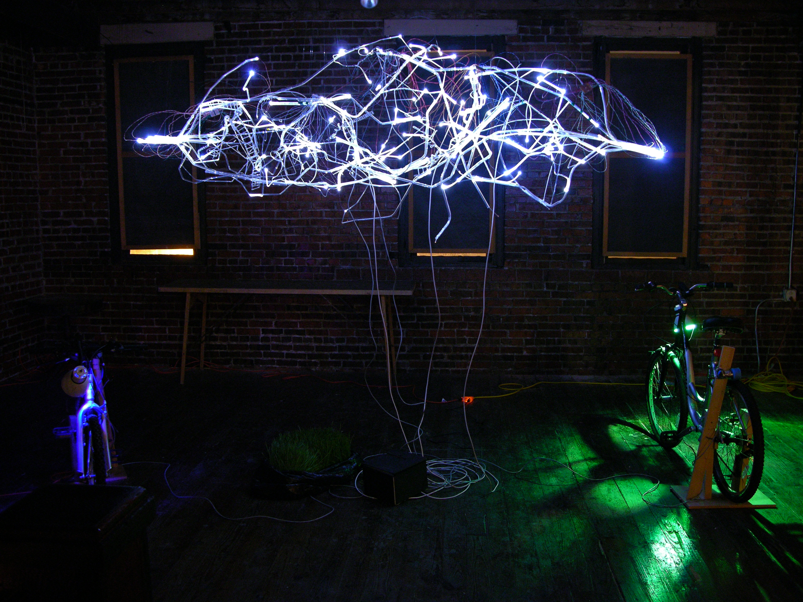
My earlier edge-lit plexiglass demo was a study for an art/technology collaboration with Lisa Rundstrom that became known as “Organic Energy Cloud,” installed at Diver Studio for the November 28 Final Friday.

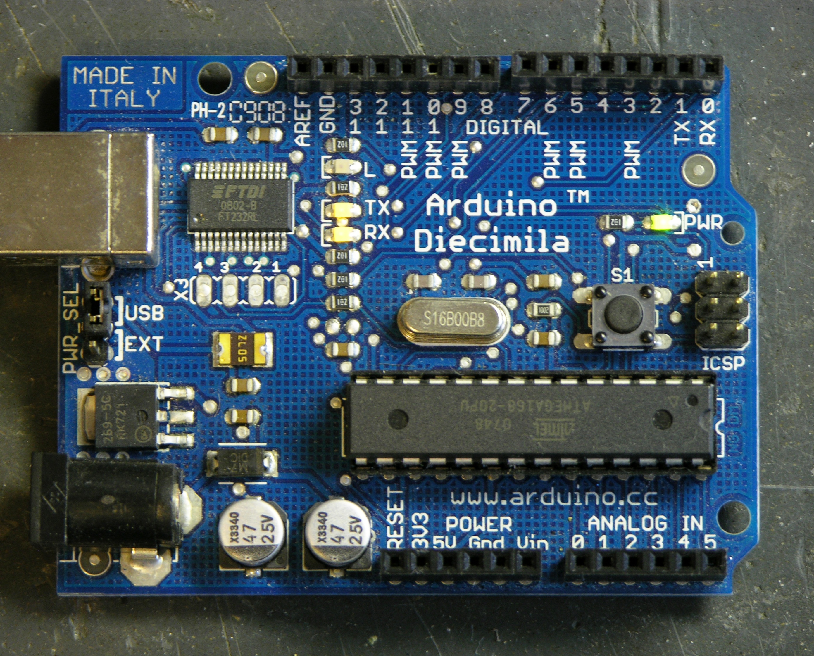
Lisa and I ended up agreeing on 200 LEDs (and ultimately installing 160). I had decided early on that I wanted to use two A6276 16-LED drivers to a board, for distributed LED control, all run by an Arduino. Once I got all my parts, over the November 22 weekend, I designed and began assembling the driver boards.

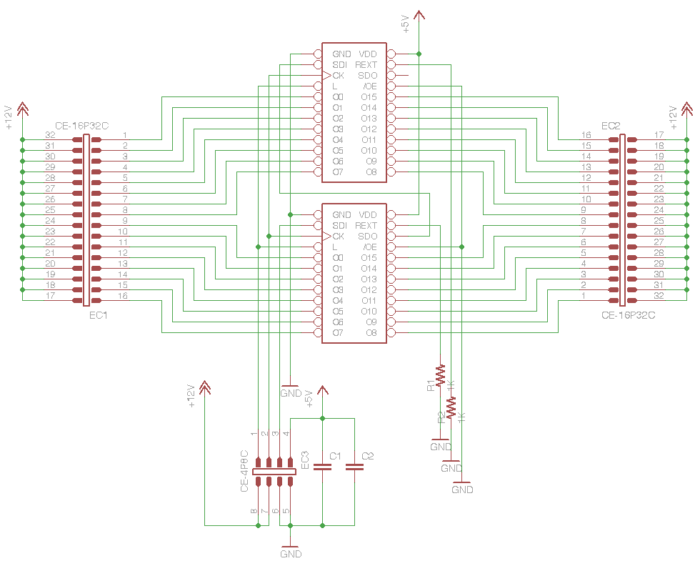
Schematic and Boards

A6276 32-LED driver schematic

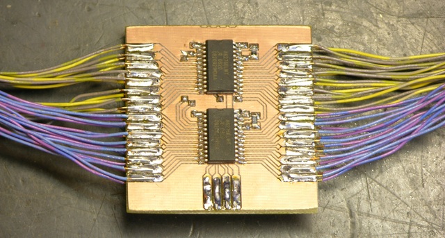
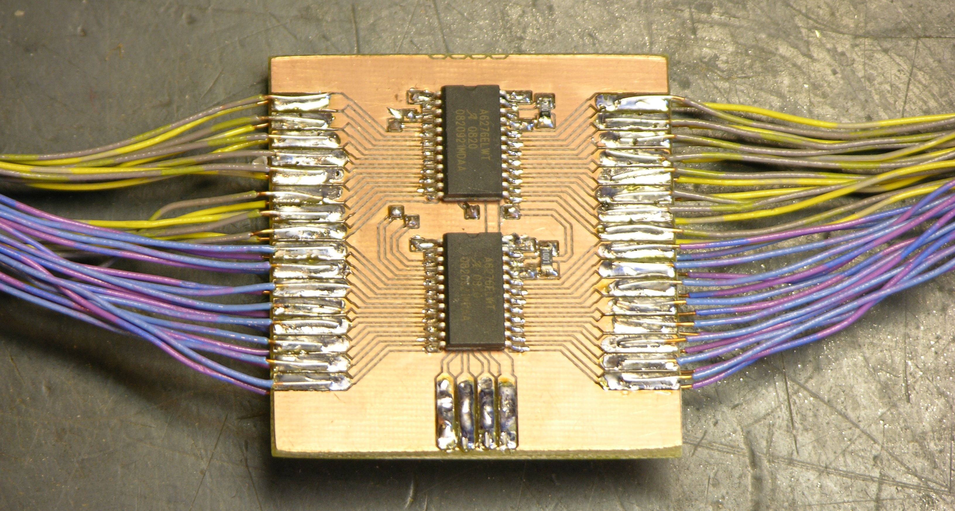
The schematic is dead simple — daisy-chained A6276es, common clock and latch lines, output enable tied active (low). For speed and cost, I planned card-edge connectors to solder all the LED and “umbilical” connections to. Although the A6276 doesn’t have separate digital and analog grounds, I used separate wires in the umbilical for digital and LED V+, and I doubled the GND and LED V+ lines for current-carrying capacity.

Copper PCB with A6276 LED control boards milled

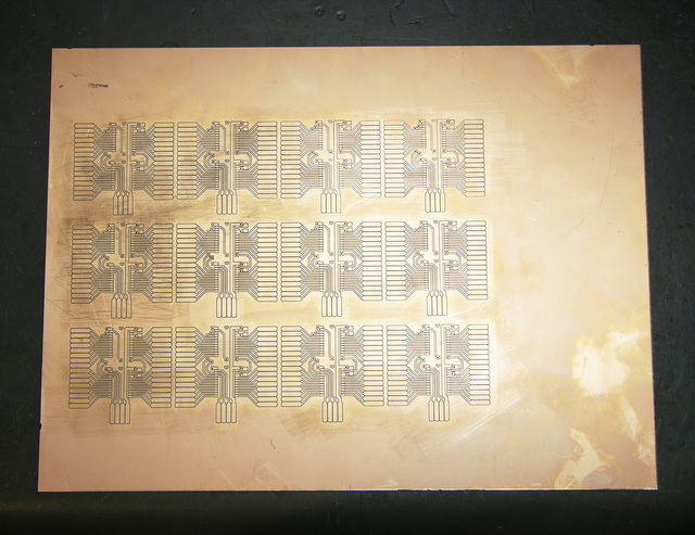
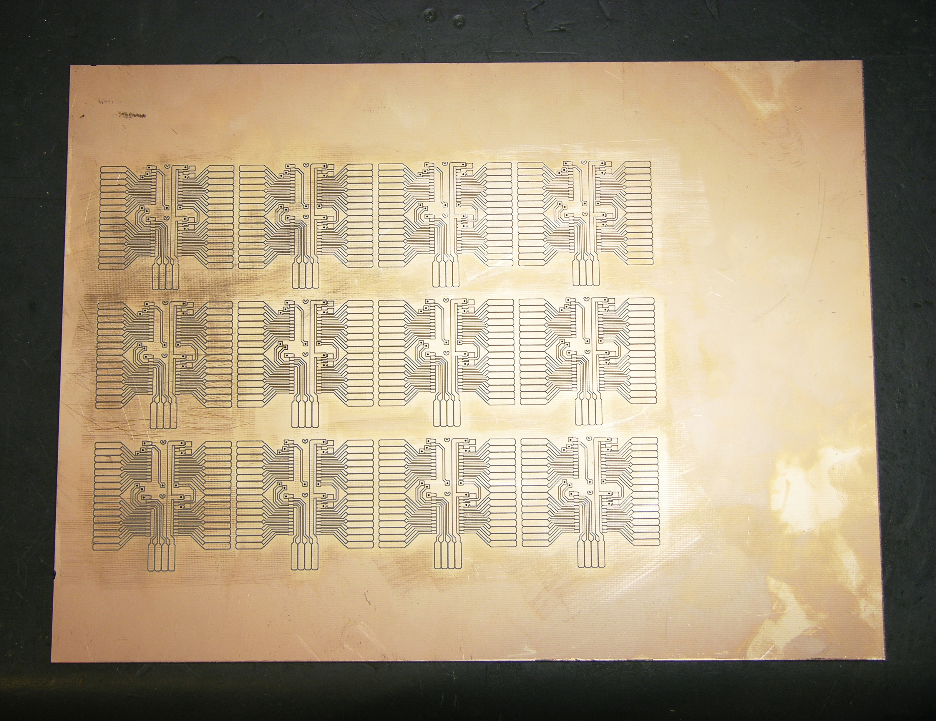
I hand-etched a prototype PCB to make sure the design worked, but it was pretty time-consuming and not my most beautiful work (especially being a two-sided board). Tom McGuire milled me a much more beautiful set of boards (although not using that mill), and did a very nice job using the drill holes as registration marks to line up the milling for the back side.

Assembly

Monday the 24th, I started pressing my friends into service for slave labor. Jeremy and Mindy were my first victims, and together we got all the PCBs and about half the LEDs assembled. Jeremy was stripping wire ends and Mindy and I were soldering — she did a fantastic job, especially for someone who had never soldered electronics before.

Soldering wires to SMT LEDs with clothespin vise

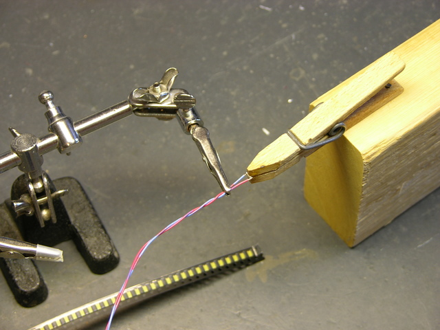
The key to retaining a shred of sanity while soldering wires onto SMT LEDs is a good soldering jig. Sunday night while assembling my prototype control board, I had tried to assemble LEDs with just the helping hands vise, and the LEDs kept going crooked in the alligator jaws. It took me about an hour to solder sixteen, and I knew that wouldn’t get 200 done in time.

I figured my mom still had some wooden clothespins, and after a little quality time on the disc sander, I had some perfectly elegant, incredibly functional SMT LED soldering jigs. Production speed skyrocketed; frustration plummeted; stabbiness dissipated.

Assembled 32-LED controller

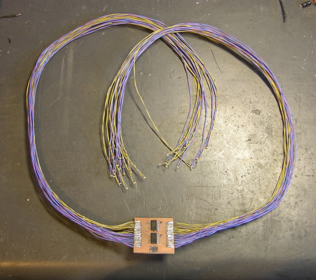
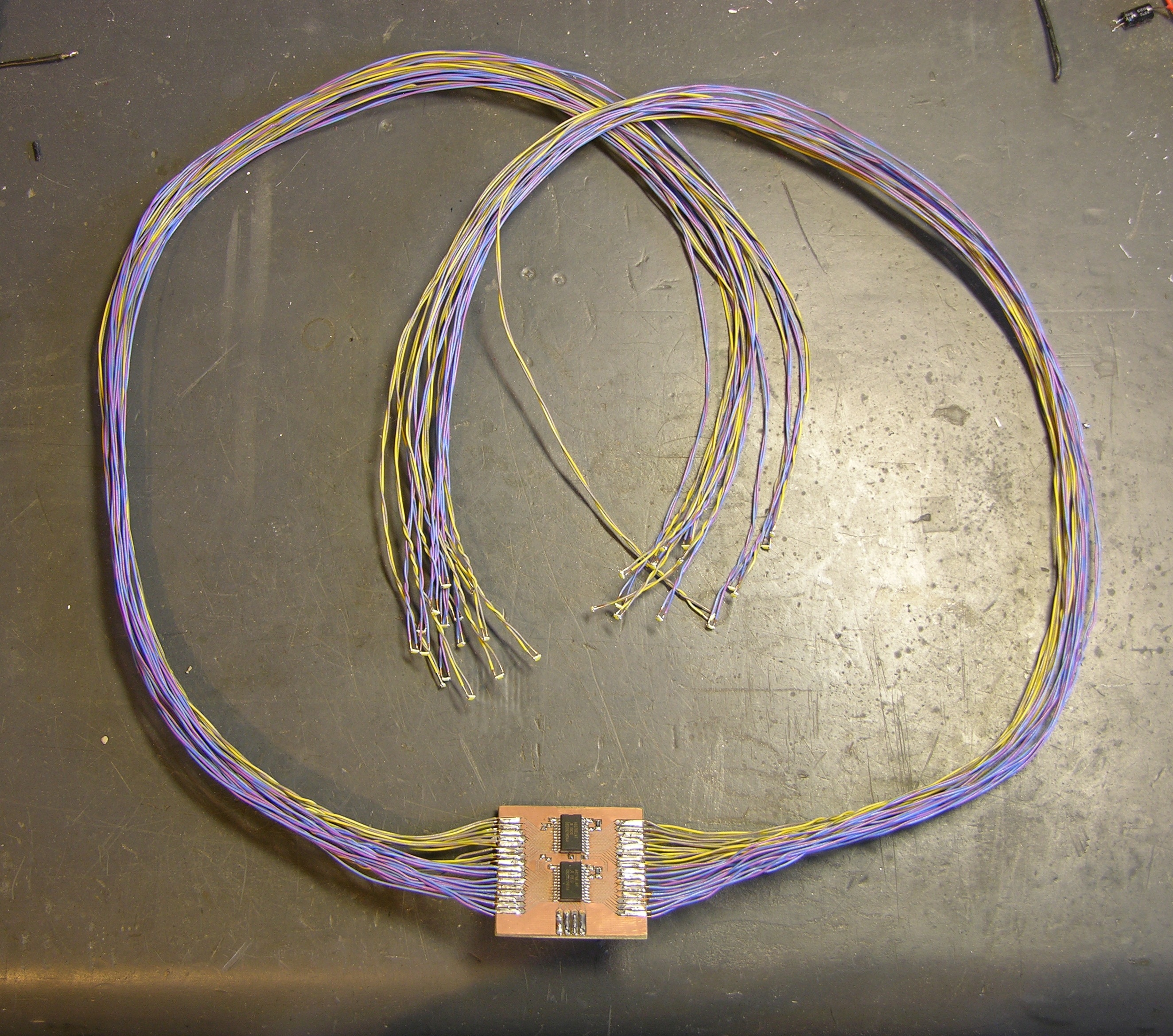
With the LED wires attached, and especially once the umbilicals were on (not shown here), the controllers really reminded me of facehuggers.

Rather than try to size LED wires specifically for LED placement within the piece, we made them all the same length. Lawrence, Gail, and the kids (especially Phill and Jake) stayed up late the next night helping me finish soldering LEDs and assembling the controllers.

Bus

I designed the controllers so that the clock and data lines would run in parallel to every board, but each board would have a separate latch line. It doesn’t matter what’s in the A6276′s internal serial buffer — it only matters when that chip gets its buffer latched to the outputs — and this arrangement made for a minimum of connections to the Arduino.

I knew we were going to be plugging and unplugging the umbilicals from the Arduino multiple times before we got everything assembled; but because of the parallel bus arrangement, there were too many wires to plug the umbilicals directly into the Arduino’s headers. I thought about plugging the bus together on a breadboard, but it would have made for a lot of jumper wires for the paralleled lines.

Organic Energy Cloud bus

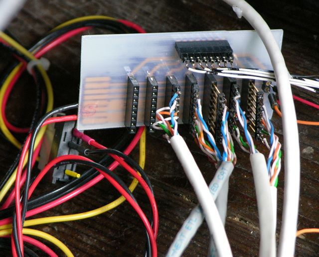
It ended up feeling easiest to design a small bus board with female headers on it, with the power, data, and clock lines bused, and the latch lines run to a separate 8-pin header at the top. (The bus board could run eight controllers — 256 LEDs — although we only ended up using five controllers.) I would have chosen to use ribbon cable to connect the latch header to the Arduino, except I forgot about that jumper and had to make something quickly out of borrowed wire while we were doing the gallery installation.

All Together

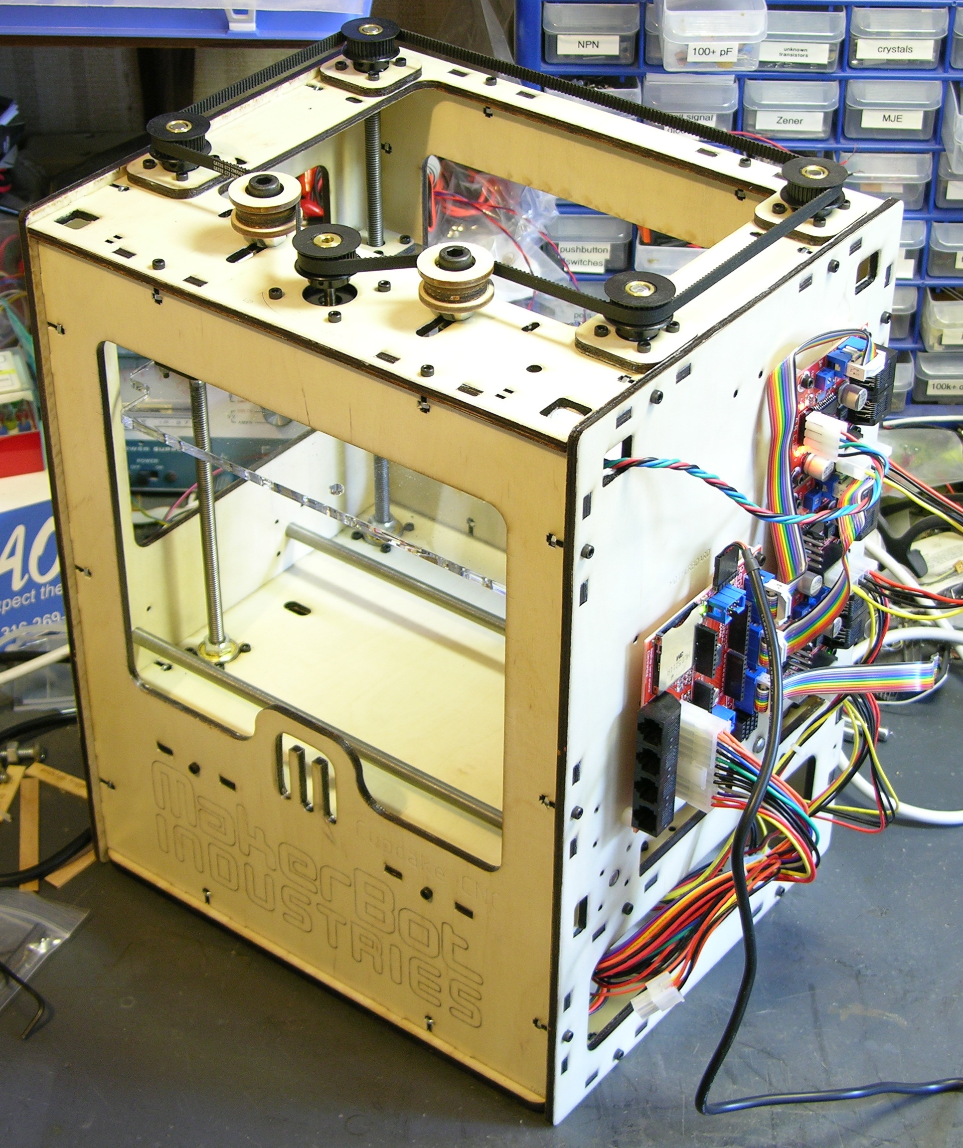
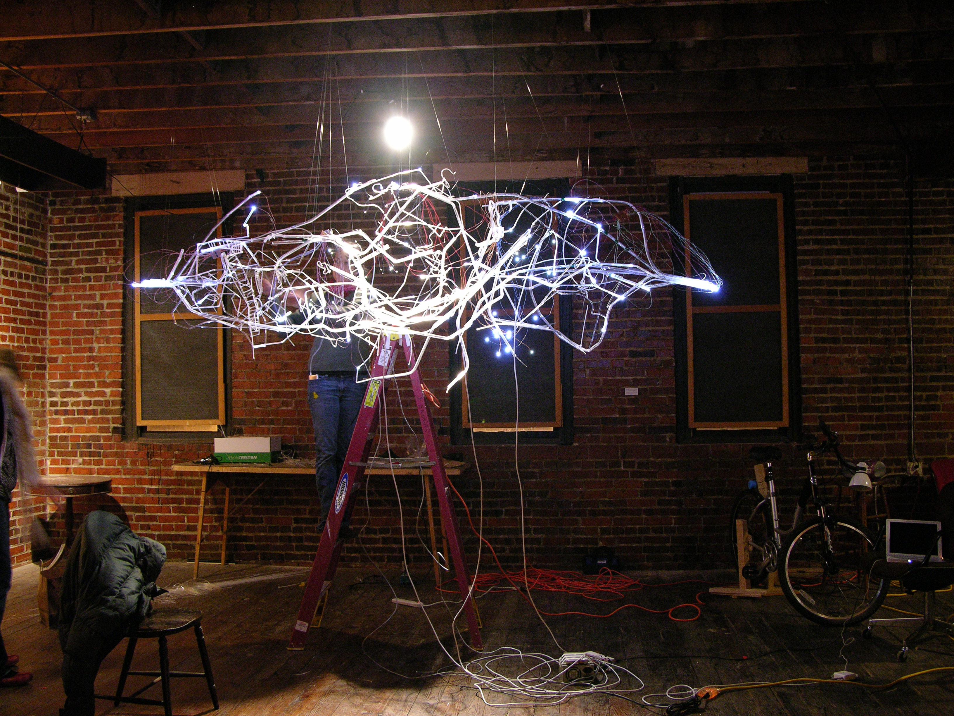
Because I was prepared to run 200 LEDs at ≥ 20mA each, the small power supplies I have weren’t going to be up to the task, and I used a PC power supply, not visible here except for its DC power cables.

Arduino and Organic Energy Cloud bus/wiring

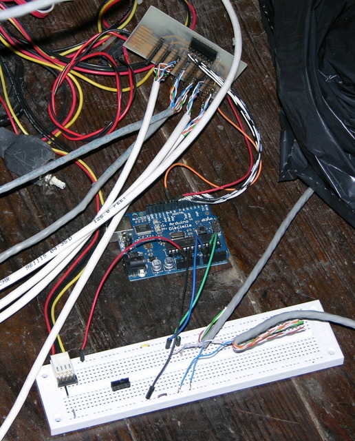
The Arduino is plugged into the bus and the PC power supply, and in the foreground is a breadboard for a part of the project that didn’t come to fruition. This is actually how it sat during the show — Lisa is fascinated by technological infrastructure, and the mess of wires was part of the “organicness” of the piece. More on that in a follow-up post on the installation.

Controller Enhancements

32-LED controller, closeup

Soldering all the LED wires to the card-edge connectors turned out to be a bit of a chore with someone helping with two vises and a needlenose pliers, and incredibly tedious to do alone. All along, I’ve been thinking about how I could design or redesign the controllers so they’d be practical for artists to use without me there to assemble everything, and these boards just aren’t suitable. I have three crucial considerations that weren’t anywhere near met:

  • Wiring the LEDs to the board needs to be easy. (Soldering individual wires was time-consuming and hard to do alone.)
  • Replacement of burned-out LEDs needs to be easy. (Desoldering wires from the controller and resoldering new wires isn’t practical, especially once the board is installed in a piece.)
  • Replacement of burned-out boards needs to be easy. (Desoldering all the wires from a bad board would be a nightmare.)

So ideally I’m looking for a connector that would make it quick and easy to change individual connections on the LED side, and also quick and easy to change a whole batch of connections on the board side — like a daughtercard with an edge connector on the bottom and jacks for LED wires on the top.

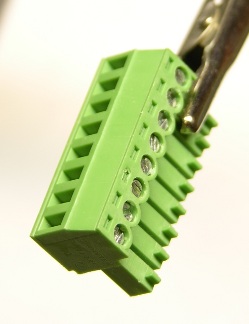
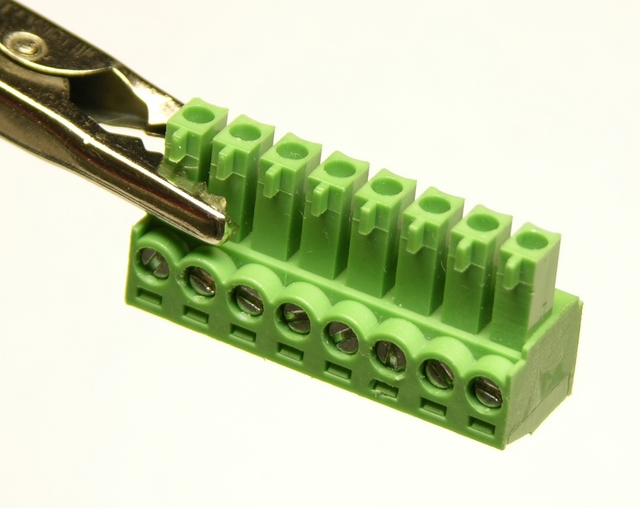
Coincidentally, the week after the show, I was at Anixter’s Chicago facility evaluating replacement keycard door access control systems for work, and I found what looks like the perfect connector on the back side of some HID card readers. The connector has screw terminals on the top for the wires that go to the door strike, motion sensor, etc., and plugs on the bottom to snap the whole thing into the socket on the card reader. The guys from the lab told me they think it’s called a Phoenix or Buchanon connector, and kindly gave me one to take home!

Pluggable terminal strip, top side

Pluggable terminal strip, bottom side

Now I just need to spend some time going through about a hundred pages of the Digi-Key catalog to see whether they carry this, and maybe to see what else they have that’s similar and might be even better.

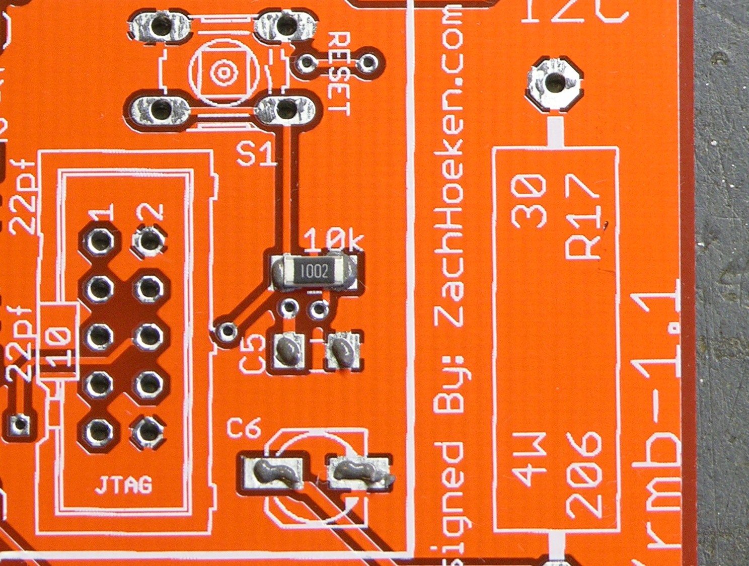
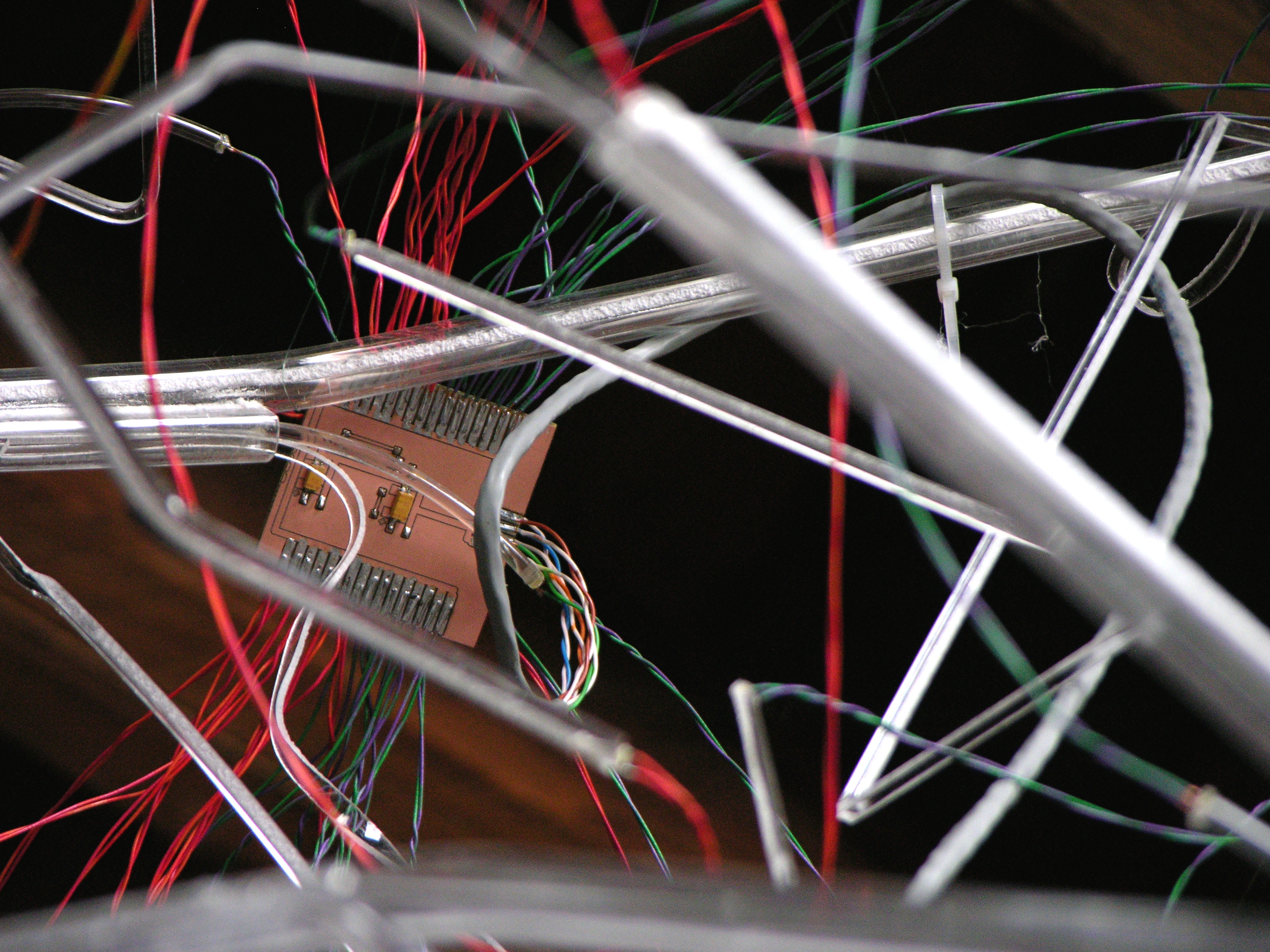
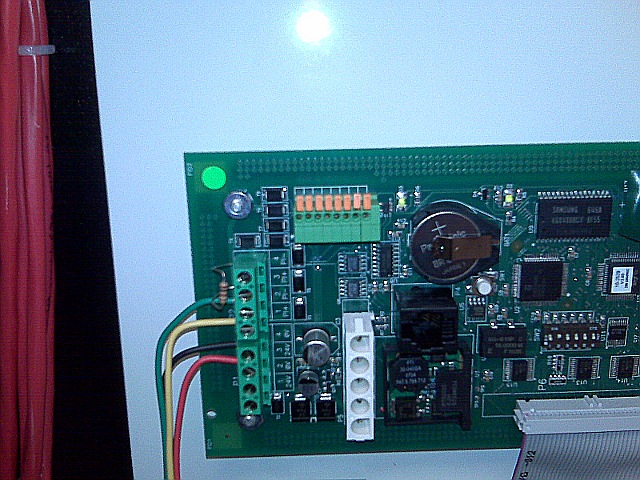
Meanwhile, this past weekend during a scheduled power outage in our computer room for some kill switch and fire suppression work, I found this connector (upper left) inside the fire alarm control panel. (BlackBerry camera + closeup == fuzzzzzzz . . .)

Fire suppression control panel with quick-release wire connectors

Fire suppression control panel with quick-release wire connectors

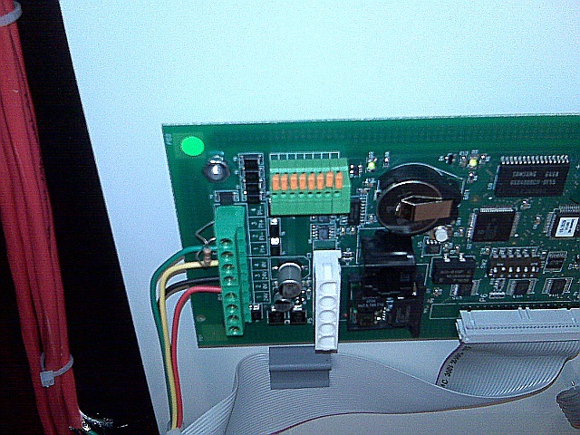
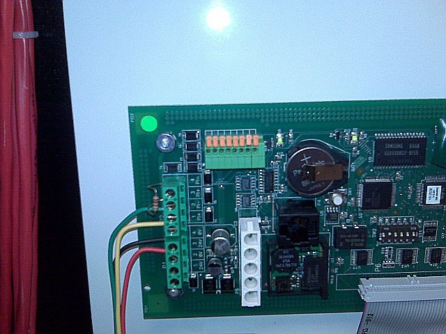
I really like the orange quick-release levers on this — it’d sure be handy for hooking up the wires in the first place (presuming, as with the screw terminals above, that one is using a large enough gauge of wire that one can clamp them and make good contact). I also love that the wires feed out the top of the connector instead of the side. But it doesn’t offer bulk plug action like the above Phoenix-or-Buchanon connector.

Especially if the two had the same pin spacing, maybe one could offer boards with choice of connector. I think I’d pick the quick-release connector for use in a project with only one or two controllers, and the two-level connector for use in a project with lots of controller boards.

More quality time with Digi-Key for me.

Arduino on the Go

Thursday, July 31st, 2008

A week-long vacation without the Arduino? The horror . . . the horror . . .

Arduino, LCD, and breadboard on foam-core sheet

Arduino, LCD, and breadboard strapped down on foam-core sheet, for travel.

Arduino MIDI Volume Pedal

Saturday, July 12th, 2008

I’m playing keyboards this fall in another rock concert to benefit the high school robotics team, and for some of the tunes I need to be able to fade an organ in and out over a period of a measure or two. My keyboards are velocity-sensitive, so if you hit the keys harder they play louder (like a piano); and they have aftertouch, so if you press down extra-hard on the keys you can get special effects. But there’s no good way to change the volume of their organ sounds dynamically, and these synths don’t have inputs for volume pedals.

This is the MIDI volume pedal project I was starting to work on when I took apart a Baldwin organ swell pedal and decided to leave it intact based on what I found inside. I got another analog volume pedal from a pile of unknown origin at the school lab and finished the job.

Homebrew MIDI volume pedal using Arduino

(more…)

LED Calculator with Rotary Quadrature Encoder for Target System Voltage Selection

Sunday, July 6th, 2008

LED calculator with rotary encoder for target supply voltage

I’m still working on the LED calculator (original idea and most recent work) — I’ve finally got ’round to adding a rotary encoder to set the target system voltage. Now you can turn the potentiometer to set the LED brightness, turn the rotary encoder to set what voltage will be used in the ultimate LED circuit, and read the LED voltage, current, and current-limiting resistor values off the screen.

I also found the Ω in my LCD’s character matrix, so I tidied up the display a little.

And most significantly, I wrote an Arduino library for reading (multiple) quadrature encoders. The simple approach of polling them inside loop() was causing me to lose a lot of steps from the encoders; and the code to read them using hardware external interrupts (lower on the same page) only works on digital pins 2 and 3, so only supports one encoder if both pins are wired to interrupts for the highest resolution, or two if interrupting on a single pin and polling the other.

My Quadrature library uses the TIMER2 overflow interrupt service routine to poll multiple encoders rapidly and track the results, supporting as many encoders as you have room for on the digital pins. It also encapsulates all the dirty work into the library code, so using it is as simple as

#include "Quadrature.h"

Quadrature myencoder1(9, 10);  //  Connected to pins 9 and 10

loop() {
  x = myencoder1.position();
}

It still has some rough edges and it’s by no means perfect (more on that below), but it sure makes it easy to use rotary quadrature encoders. It’s available on a new Downloads page for anyone interested.

(more…)