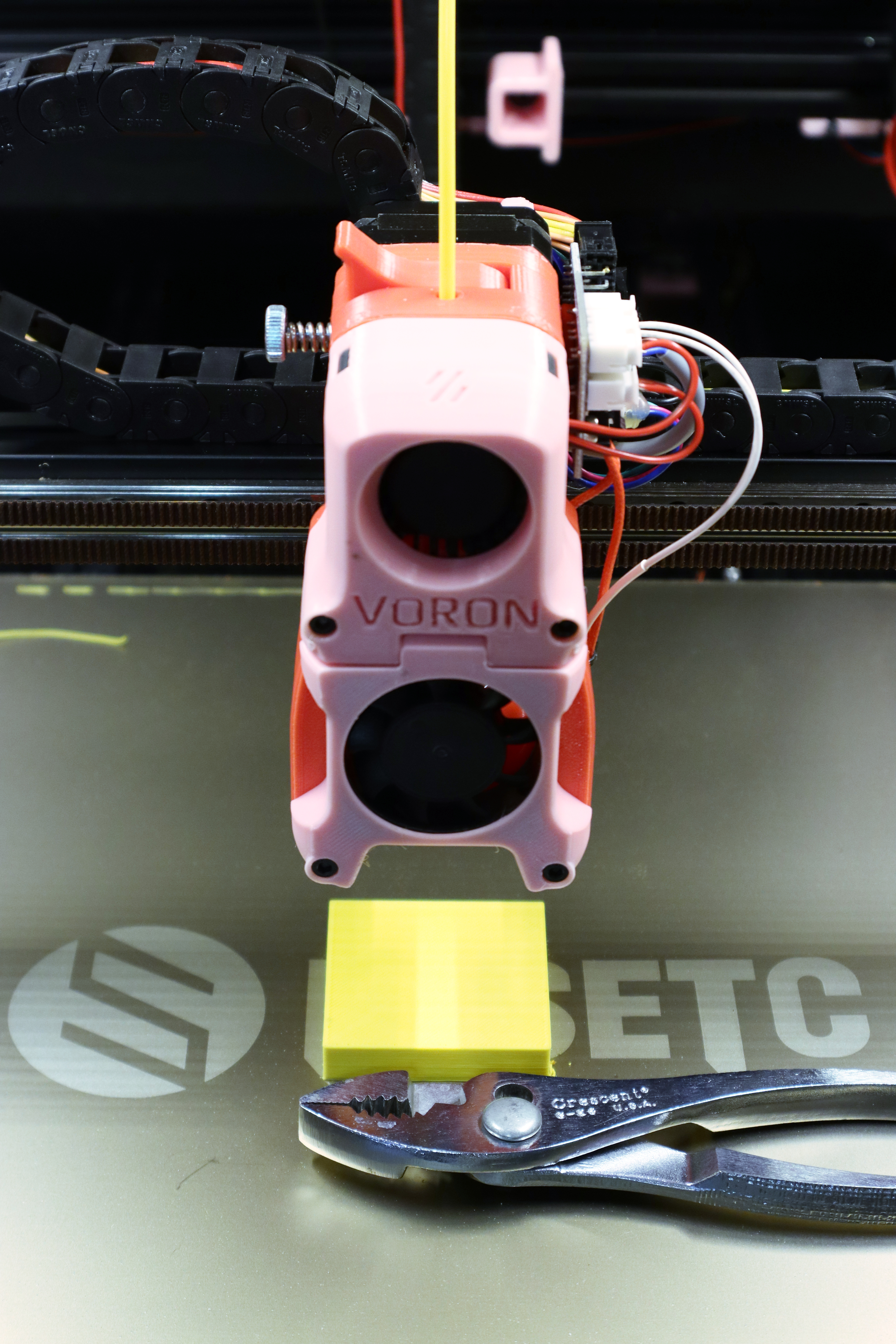
Last week I started measuring the repeatability of my Voron 2.4′s Z limit switch and got very not-repeatable results.
Since the first layer’s ability to stick to the build platform relies on a repeatable height above the build platform which in turn relies on a repeatable measurement from the Z limit switch, this had to be corrected before proceeding — lack of repeatability here breaks everything the printer is trying to do! So I needed to find and correct the source of that deviation.
My first thought was to take apart the switch assembly and see whether anything had gone wrong between the plunger pin and the switch. But before I even got that far,
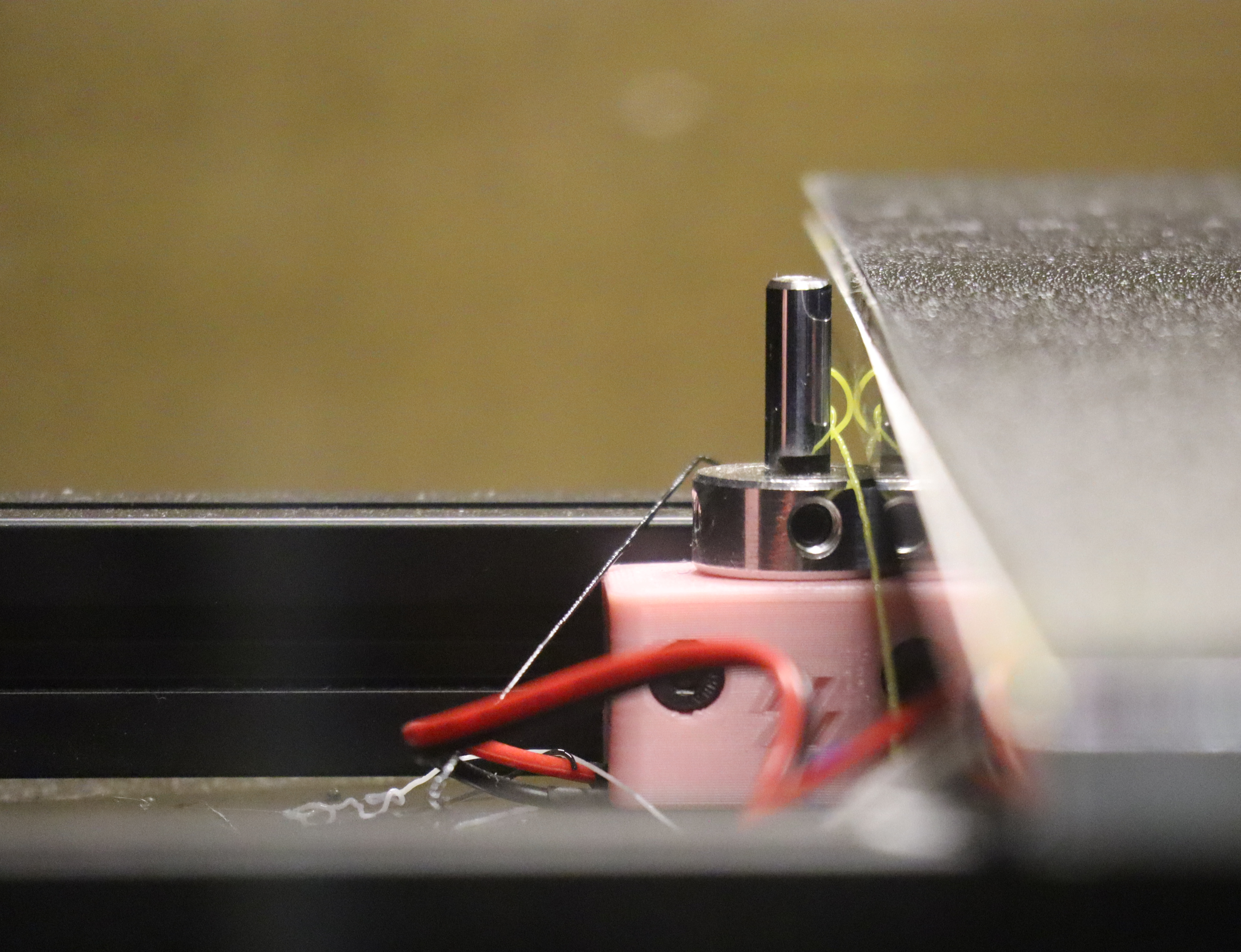
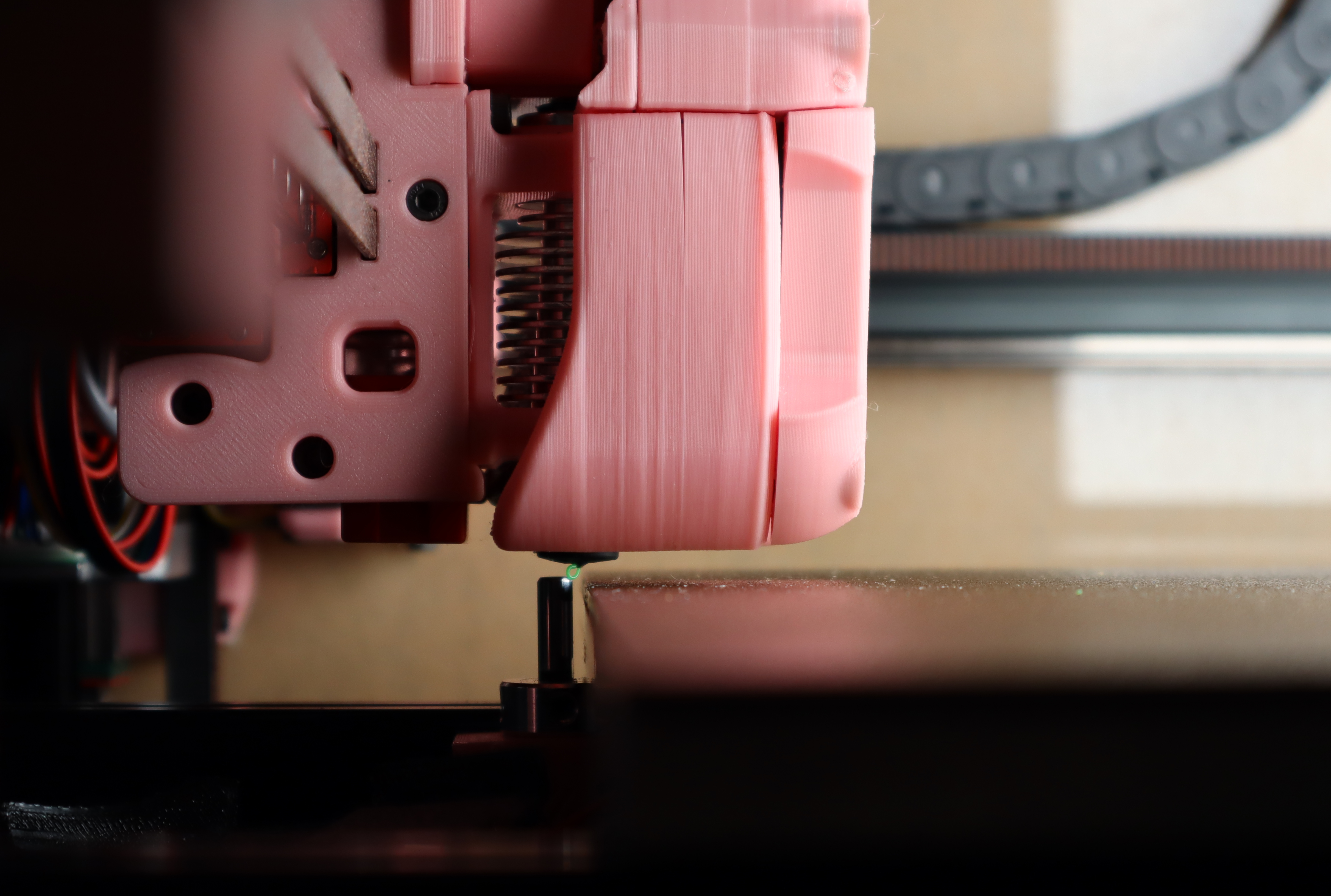
I found all these filament droppings (oozed out of an idle hot nozzle — call them fwarf?) piled on and around the switch assembly. Although the only way I could imagine them impacting a reading like my previous trial would be if one had laid on top of the pin during a reading — and I’d been sitting there to see that none had — I figured I’d better clean them out and rerun the collection of calibration samples.
And while doing so, I found what appears to have been the actual problem:
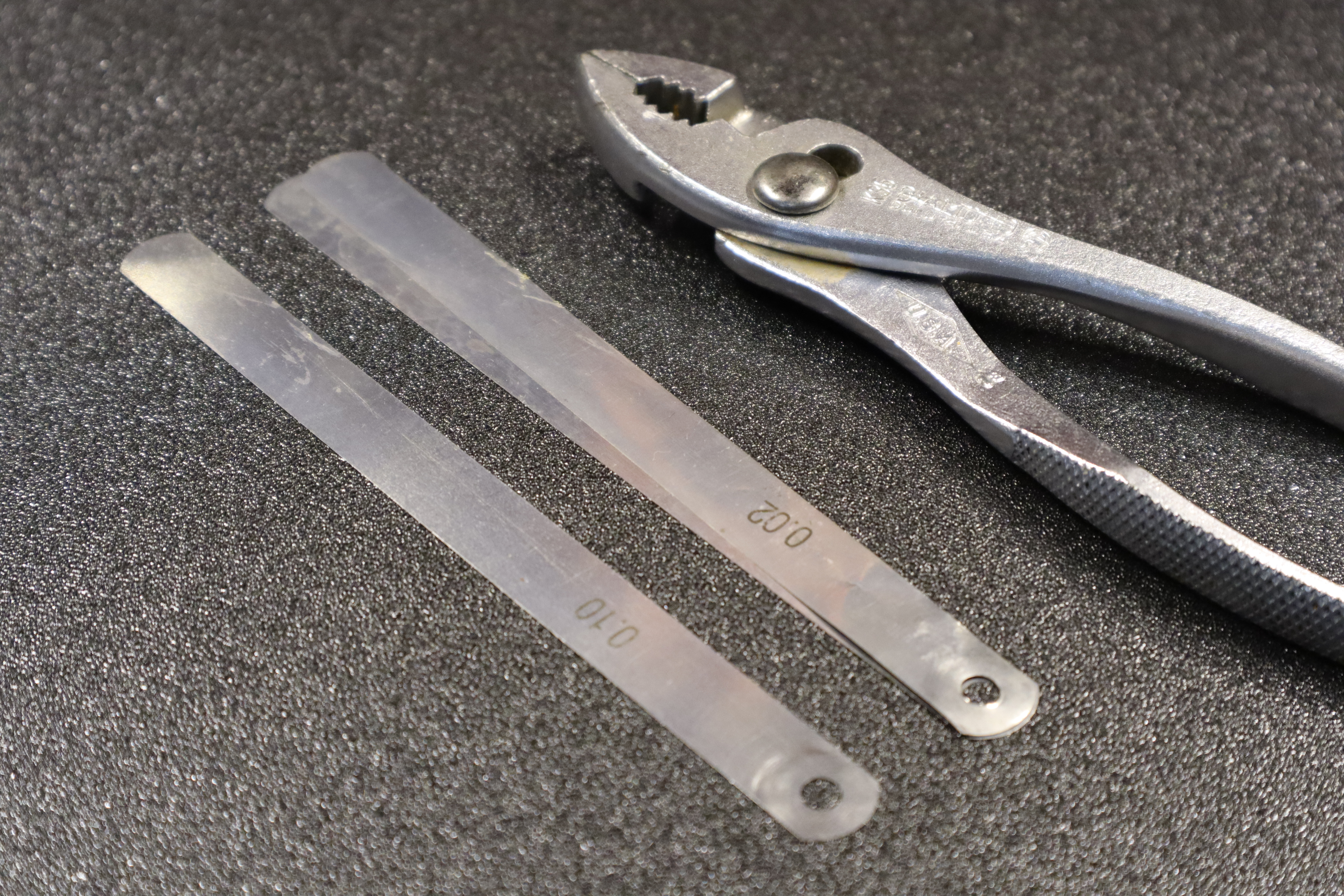
When performing the first Z_ENDSTOP_CALIBRATION, when I got the nozzle closer to the platform than the thickness of my 0.10-mm feeler gauge, I swung the 0.02-mm feeler gauge out of its place in the holder and it delaminated and split in two. Uh, what????? Oh. Oh, it’s so thin that the 0.03-mm feeler gauge was stuck to the back of it and I swung both of them out together. I … uh … wonder how many times I’ve done that before. Randomly. On some of the measurements and not others.