Scooba Second Impressions

February 10th, 2009 by Keith Neufeld

Scooba 5900

My first impressions of Scooba were based on not yet having the official Clorox cleaning solution and running with vinegar water. I got my shipment of the Clorox solution yesterday and ran four cleaning cycles on the bathroom floor. New notes:

  • I had left both batteries fully charged but off the charger for a week, and Scooba reported one as completely dead and the other didn’t make it through a full cleaning cycle. Looks like I’ll need to keep them on the charger and/or use them more frequently.
  • The Clorox solution smells good! (Remember that vinegar is my grounds for comparison . . .) It smells like a cross between some kind of detergent and your widow grandmother’s soap-scented bathroom.
  • The Clorox solution seems to clean a little better than the vinegar water — that is, leaves the floor noticeably cleaner. Scooba made visible progress on the dark marks in the faux grout lines on our vinyl floor.
  • The Clorox solution puts a shine on the floor! I don’t consider it perfect or done, but the bathroom floor looks way nicer than it did before getting Scooba or after running with vinegar.

Note to other secondhand Scooba owners: Buy the Clorox!

Storage Storage for Samples Storage

February 9th, 2009 by Keith Neufeld

In the past, I’ve tried several techniques for organizing my small quantities of IC samples (and “purchased samples”). I have enough different ones and each needs so little space individually that I don’t really want to dedicate parts bins to them.

IC samples in different containers

I’ve tried putting them in pockets in a three-ring binder, leaving them in the open shipping carton, and leaving them lying around on my workbench in their packages.

None of these have worked particularly well for me.

Mainframe Backup Tapes

At work, we have a large collection of “3490″ mainframe backup tapes, and they’re kept in large racks without the plastic cases the tapes ship in. In the IT environment, large sets of disks and tapes are referred to as “storage;” so the empty plastic cases and the racks the tapes go in are “storage storage,” right?

We had a few empty tape cases left, which were of no use to us and which I took home. We’ve also retired our mainframe and pruned our backup collection, so we have a number of empty racks and rack cases sitting around. It looked like an opportunity to salvage discarded materials and improve my electronic parts storage.

Tape Packages for Electronics Parts

Stacked tape cases with ICs

Last night I put most of my samples into empty tape cases, and it worked quite well. At Wal-Mart I found some Avery labels that are compatible with #5366 (2/3″ x 3 7/16″, called “File Folder — White”), are ultra-opaque, are supported by the label feature in OpenOffice, and fit nicely onto the approximately 1″ x 4.25″ case spines.

Racks (Or Not)

The cases have ridged edges and stack very nicely, but I was hoping to get them into a rack for easy “random access” to individual boxes.

Data tape case doesn't fit into tape storage rack

Unfortunately <grunt>, the racks <grunt shove> weren’t made to hold the cases <curse shove>, just the tapes <growl>, and the cases don’t fit <sigh resignation>.

Boxed tape cases with ICs

I still have some of the boxes that the tapes originally shipped in, but this isn’t necessarily an improvement over just stacking the cases. They’re still sort of “latched” together in the boxes, and it’s almost more difficult to pry a case out of a full box than to balance a stack of cases whilst removing a lower one.

I’ll keep looking — hopefully there’s a rack out there that fits the cases, that someone doesn’t need any more, that I can save from the landfill, and that I get for free. :-)

Speaker to Preamp Adapter for Jeremy

February 6th, 2009 by Keith Neufeld

Jeremy and I have been kicking around ideas we’d like to see in a 1U rackmount audio mixer. I’d like to be able to mix my synths and digital piano together with another audio source so I can play along with a CD to figure out the keyboard part, without having to have separate speakers for the keyboards as I do now. Jeremy would like to be able to listen to his own selection of background music while he’s playing (some) video games at his entertainment system and projector. I’d like to be able to record my synth output into my iBook without having to disconnect and recable everything — and without necessarily recording audio from the CD I might be playing along to.

Once we figure out the number and types of inputs and outputs we want, we’ll go shopping and see if such a mixer already exists at a price commensurate with our needs. If so, buy. If not, talk about building.

Meanwhile, we got distracted by Jeremy’s receiver. Some of his audio sources are digital, so we thought we’d need his receiver to decode them before going to an analog mixer. And his receiver doesn’t have an effects loop or tape monitor, so we’d need to use line or preamp outputs and an outboard amplifier for at least his main speakers. And he doesn’t have preamp outs, so I started talking about tapping his speaker outputs and at about that point this degenerated into a game of “okay can we just get his receiver to feed through one of my SAE A502 amps and power his speakers.”

Speaker to preamp adapter, top

The answer, of course, is yes.

And by the way, all of his digital audio sources have analog outputs right next to them that we can use for our analog mix, so all of this was completely pointless. :-)

Read the rest of this entry »

LM34DZ Fahrenheit Temperature Sensor

February 2nd, 2009 by Keith Neufeld

This started as notes I made to myself long ago for the LogoChip, but they apply equally to the Arduino A/D converters.

The LM34DZ is a temperature sensor in a TO-92 case available from All Electronics for $2.50. It has the handy characteristic of reading an output voltage that directly corresponds to Fahrenheit temperature in a ratio of 10mV per °F. That is, at 70°F it reads 70 * 10mV = 700mV.

LM34DZ Fahrenheit temperature sensor

With a direct output voltage (rather than the varying resistance that many thermal probes provide), it’s perfect for hooking to a microcontroller A/D input. So, how to convert the A/D reading back into Fahrenheit temperature?

Well, the sensor reads 10mV (or .01V) per °F. Microcontroller A/D converters tend to have 5V input and read 1024 steps over the 0-5V range.

1024 steps / 5V ≈ 205 steps / V

So

(.01V / °F) * (205 steps / V) ≈ 2 steps / °F

Thus you can get a “maybe close enough” approximation with code like

tempF = analogRead(lm34Pin) / 2;

With a conversion error of +2.4%, this’ll get you within a couple of degrees at room temperature — close enough to make some macro-level observations about whether it’s getting warmer or colder for a physical computing project. Since the stated accuracy is only 1°F anyway, that’s not too bad.

If you need a more accurate conversion, you’ll need to use floating-point arithmetic if you have it (which the Arduino doesn’t [correction: does]) or find a fixed-point arithmetic library if you don’t. Or if your integer variables are large enough (at least 17 unsigned bits for temperatures up to 127°F, 18 bits up to 255°F), you can rearrange the order of calculation like so:

tempF = (1024 * analogRead(lm34Pin)) / 5;

Scooba First Impressions

February 1st, 2009 by Keith Neufeld

I love how my Roombas help keep pet hair picked up with a minimum of effort; and I’ve been fascinated by the idea of the Scooba, iRobot’s wet-mopping robot, since it was announced. I recently picked up a used 5900 in very nice condition on eBay from a wonderful seller who even included a spare battery.

Scooba 5900

I want to start with a pictorial overview, since I hadn’t seen enough Scooba pictures to understand how different it really is from the Roombas, then proceed to a few comments about my experience with it so far.

Read the rest of this entry »

Motion Sensors for Occupancy Tracking

January 30th, 2009 by Keith Neufeld

This NewScientist article from last spring shows a very cool system of motion sensors for occupancy tracking. The sensors are installed more densely than in typical buildings, so they can detect occupants’ positions fairly precisely within hallways.

The most interesting part of the system for me is the video showing playback of motion through a building — you can clearly see where people were walking, where they ended up, etc.

This seems like a natural fit for a smart house — instead of just watching where there’s motion now, pay attention to where the motion has gone and remember that there must still be someone in that room (even if they’re not moving much now).

$10 Parallax motion sensors + blinders to narrow the cone of coverage + write open-source software for the capture and playback, anyone?

Project Idea: LED Puzzle Ball

January 30th, 2009 by Keith Neufeld

A long time back, I was over at Lawrence’s house and Gail had a number puzzle up on the whiteboard that she was using with her homeschool consortium gradeschool math class.

Number Puzzle

For the students, I think Gail drew the circles with pebbles in them and the younglings had to count the pebbles and write the sums of the nodes into the edges.

For adults, it’s a lot more interesting to start with the numbered edges and fill in the vertices with numbers that make the edge sums work. It’s not hard; it’s just a little bit of a twisty way of thinking.

And you have to keep your vertices balanced enough that you don’t “overflow” an edge. For example, if you started with one pebble in the upper left, then you’d have to have four in the upper right, and then zero in the lower right, and let’s just say that zero pebbles isn’t permitted. Any solvable configuration will have multiple correct answers, but they’re constrained by overflow and underflow of all the edges of the graph.

Puzzle Ball

All of which made me think that this concept could make for an interesting LED puzzle ball. Make a dodecahedron (or a smaller regular polyhedron, or even a larger geodesic shape) with LEDs along the edges and LEDs and buttons (up/down?) at the vertices.

Start it up, the LEDs flash and wink all over the place as the controller randomizes the configuration. Use the buttons to adjust the numbers at the vertices (maybe blue LEDs) so that adjacent vertices add up to the number of LEDs on that edge. As each edge is “solved,” its LEDs change from red to green. Once you have all the edges green, you’re done.

Aesthetics

Seems like it’d be coolest as a “wireframe” polyhedron rather than a solid (or solid surface).

I think I’d prefer SMT LEDs over through-hole. 3mm through-hole if absolutely necessary.

I think I’d like the edge LEDs to be strips of nine that light up fairly symmetrically from the middle out, i.e. something like

----o----              ----o----
---o-o---              ---oo----
--o-o-o--              ---ooo---
-o-o-o-o-          or  --oooo---
o-o-o-o-o         the  --ooooo--
-ooo-ooo-      boring  -oooooo--
-ooooooo-              -ooooooo-
oooo-oooo              oooooooo-
ooooooooo              ooooooooo

I’d like the whole thing to be constructed from PCBs, no separate case. There’ll need to be room for microcontrollers and/or LED drivers. Maybe instead of having the PCBs on the face of the polyhedron, have them edgewise so the PCBs’ outer edges are the edges of the polyhedron. Internally, PCBs could be held together by jumper wires soldered together at the board edges and carrying the signaling bus from one board to another.

Gameplay

I still haven’t decided whether solving the puzzle ball would be fun or merely tedious.

I remember a particular game mode in the old Merlin where you’d press buttons and all the adjacent squares would invert state, with the goal being to get all the lights on or off. I always enjoyed that game, and the way local changes impacted neighboring cells, which impacted strategy for dealing with those neighbors. I would hope that the puzzle ball would be fun in much the same way.

If each edge has nine LEDs (1 – 9) and the game is played with non-modular addition, then the average number of lit LEDs per edge will be 5.5, making the average number of lit LEDs per vertex only 2.75 — that is, on average, only a very few numbers that need to be tried at each vertex. That doesn’t sound like a very interesting game. I could increase the number of LEDs per edge to 20ish, making the average edge sum 10ish, making the average vertex 5ish, which seems okay.

Or should there be ten LEDs per edge and operate in modular arithmetic? Would that make the puzzle too easy, having more correct solutions?

“Organic Energy Cloud” Installation

January 27th, 2009 by Keith Neufeld

This has been a tough post for me to get around to writing, mainly because I don’t feel I have particularly good pictures of the process or the result, as I was working so intently during the installation that I really didn’t have time to stop and document. But here’s what I have.

Back in November, I made a small edge-lit plexiglass demo as a technology study for a large LED and plastic piece that came to be called “Organic Energy Cloud.” I’ve already written about the design and construction of the LED driver modules; all that remains is the Arduino code and the installation.

Assembly

Lisa Rundstrom installing LEDs on Organic Energy Cloud exhibit

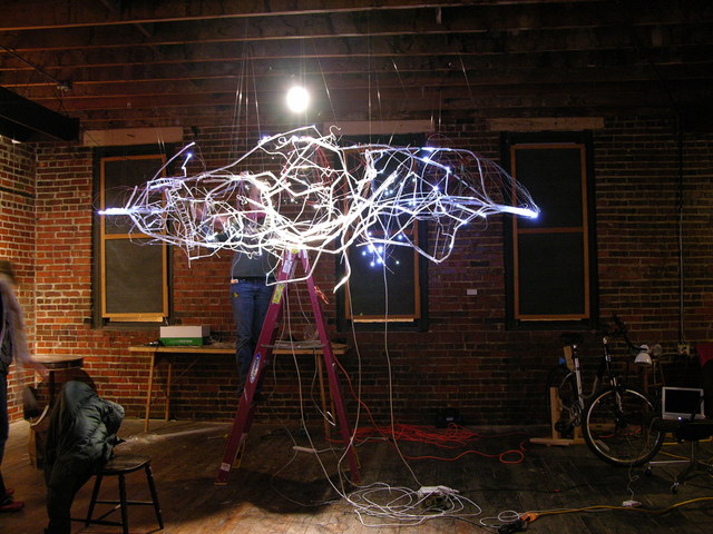
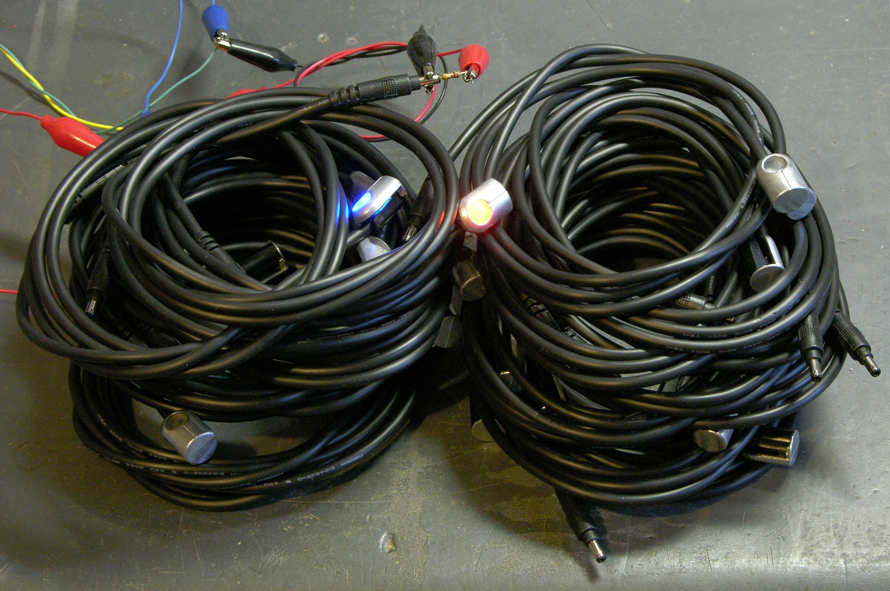
That Friday, while I was connecting all the wires together and working on Arduino code, Lisa was hanging plastic,

A6276 LED driver board, wires, and plastic in Lisa Rundstrom's Organic Energy Cloud

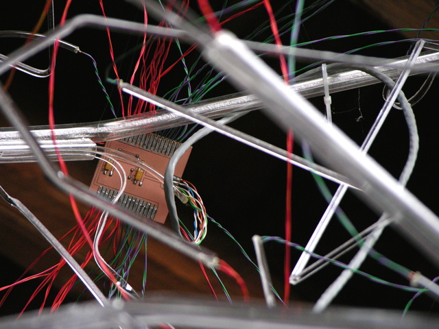
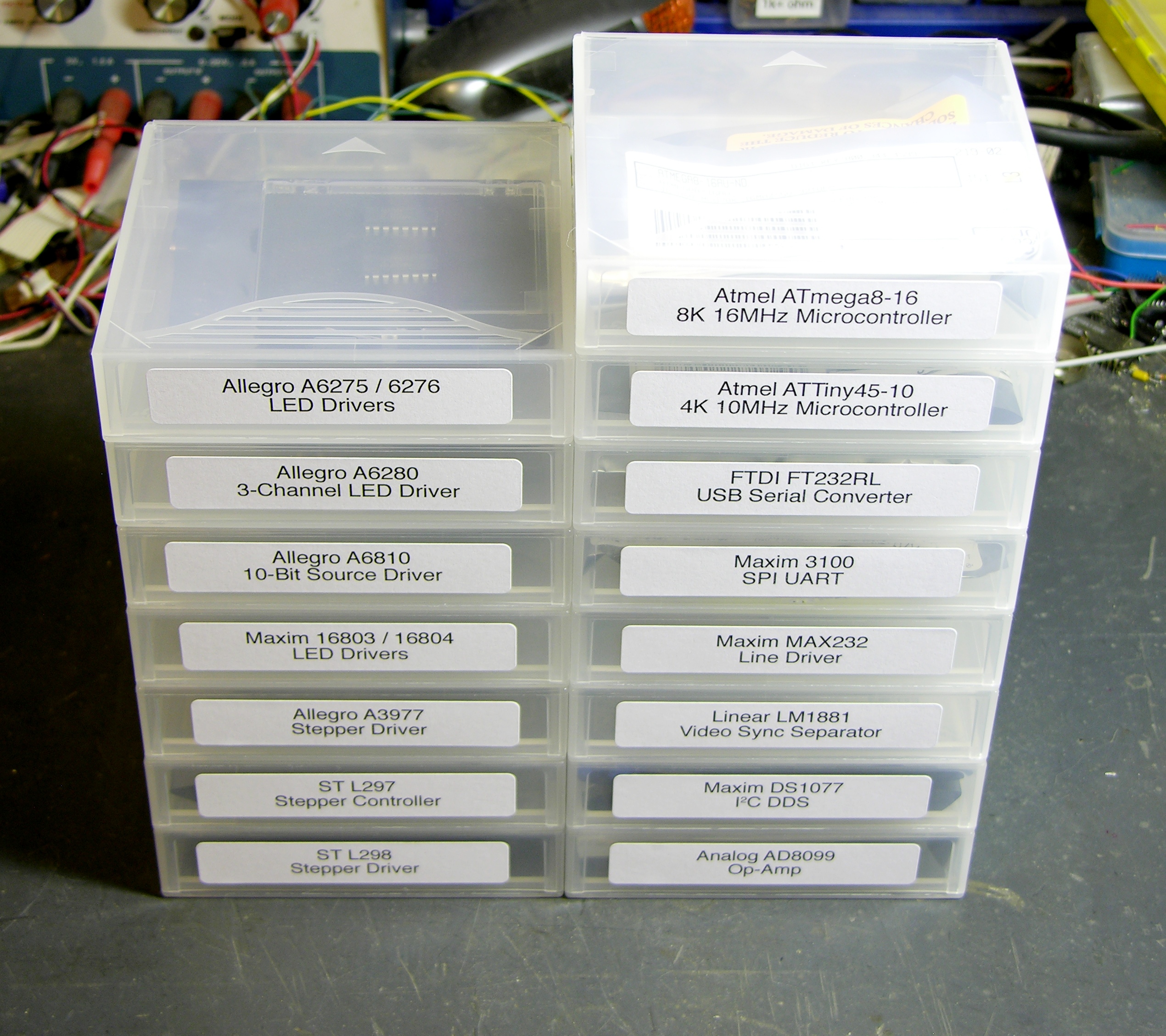
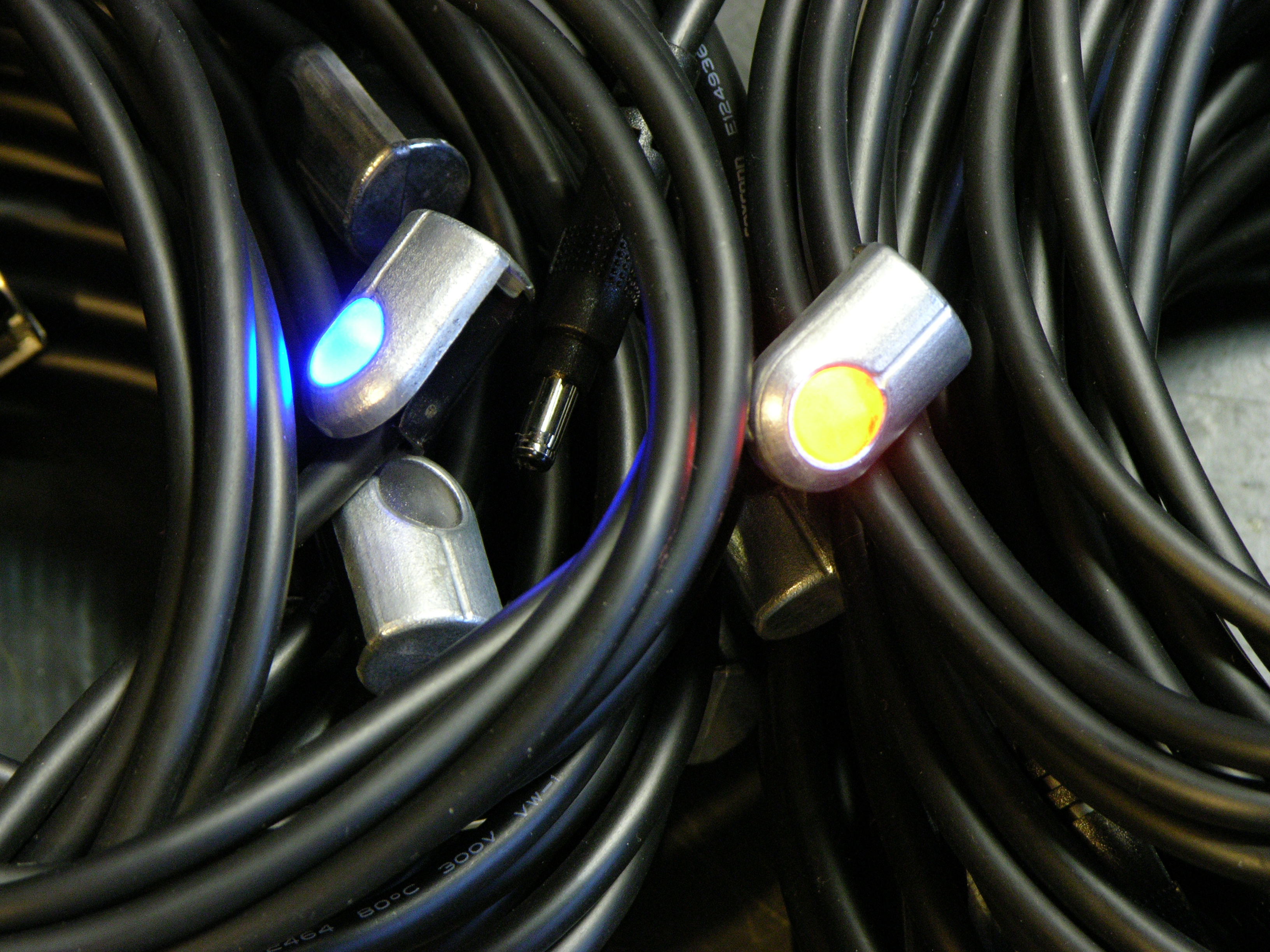
placing LED controllers in it,

Wires and acrylic in Lisa Rundstrom's Organic Energy Cloud

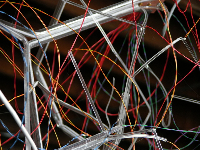
routing wires, and hot-gluing the SMT LEDs onto the ends and bends of the plastic pieces.

Melty Disaster (Having Nothing to Do with Hot Glue)

I had been programming LED patterns into the Arduino, testing and fixing some bad connections, and occasionally alarming Lisa and her helpers by making everything go dark (Alarmed words from the ladder: “Did I do something???”) or light (“Whoa!, what’s that?”).

About 18:50, ten minutes before the show was scheduled to open, I was running wire from DC motors attached to a couple of bicycle wheels (it was a bicycle-themed show called rEvolve; more on that when we collect all the materials and get the web site up) to the breadboard, and the black jumper wire between the breadboard and the Arduino melted right in front of my face.

Arduino and Organic Energy Cloud bus/wiring

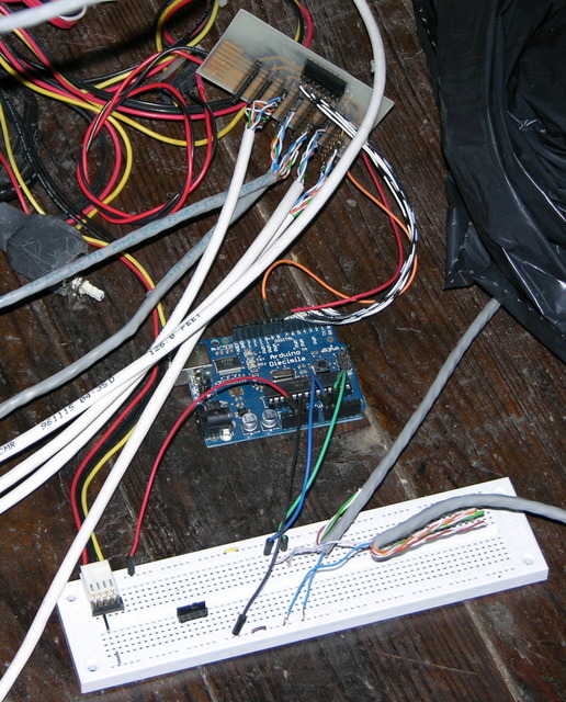
It turned bright orange, the insulation was dripping off of it, and I couldn’t figure out what tool I might have at hand that I could use to disconnect things without getting burned. It only lasted a second before it melted the wire, too — even had I jumped for the switch on the PC power supply I was using, the circuit would have opened from the wire melting before the power supply’s capacitors had drained.

After discarding the scorched ends of the jumper wire, I looked over the circuit carefully and couldn’t find anything wrong, and I still haven’t figured out what happened. The melted wire was the ground wire connecting the power supply to the Arduino via the breadboard. My wild speculation is that I bumped something that shorted, the wires warmed up and increased their resistance, and the ground wire became the resistor that now dissipated all of the circuit’s energy.

I hooked things back up and with great trepidation (and this time ready to kill power if needed) turned things back on, and they seemed to work. The Arduino booted and resumed its test pattern, the lights came on, etc. But I quickly found that I no longer had connectivity between the iBook and the Arduino.

Since the Arduino appeared to work except for the USB interface, my immediate guess was that the FTDI USB-serial chip had burned out — which turned out to be correct, and which I have since successfully replaced. I had brought another Arduino to use as a backup if anything happened to my first one; but with now five minutes before the official gallery opening, and early arrivals already wandering around, I didn’t feel I had time to swap out the Arduino, program the new one, and be confident everything was going to work.

Fortunately, I had a reasonable program running at the time, which picked a random LED out of the entire piece and then randomly turned it on or off:

  cont = FIRST_BANK + random(LAST_BANK + 1 - FIRST_BANK);
  led = random(32);

  if (random(10) > 3) {
    leds[cont] |= (long) 1 << led;
  } else {
    leds[cont] &= ~ ((long) 1 << led);
  }
  a6276_long(leds[cont]);
  a6276_latch(cont);

If that doesn't make sense, spend a little time thinking about how you would program a nice, random flickering effect with a bunch of LEDs.

Here's the whole program, commented-out test code and all, since even this was still supposed to be test code. That's what we left running all evening.

And the Show Goes On

Lisa Rundstrom's Organic Energy Cloud exhibit

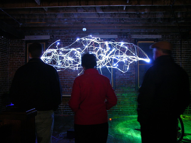
Ready or not, the lights go out, the people come in, and the girls at the refreshments table start serving coffee and hot chocolate "with or without something fun in it."

Lisa Rundstrom's Organic Energy Cloud exhibit

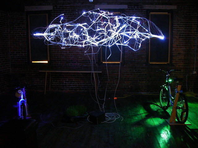
This piece deviated far from its original conception, and also ended up not being fully realized due to scheduling and time issues, but it's only fair to show it with the bicycles, even though they no longer made sense as part of the exhibit.

Finally, here's a video of the cloud that was shot by Tom McGuire. Tom had already posted it to YouTube, but I found that the compression had blurred almost all of the detail. He graciously gave me a copy of the raw footage from his camera (which looked fantastic), and between iMovie and Vimeo, I think I managed to keep a little more detail in some of the closeups.

Aftermath

Lisa Rundstrom's Organic Energy Cloud by the light of day

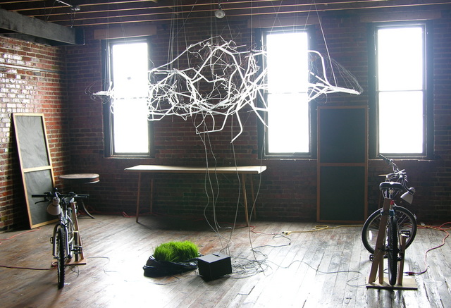
The group opened the gallery for another show on the next Thursday evening when I had to be out of town, and we had to be cleared out of the space by that Saturday morning. Arriving at 06:00 Saturday gave me a chance to take a few more pictures with the space lighted, which show a little more detail of the components of the piece and of the space in which the cloud was installed.

Project Idea: Build a Better Looper

January 26th, 2009 by Keith Neufeld

Jeremy and I have been playing with my “new” Akai Headrush E2 looper pedal, which allows you to record an instrument (or whatever) into it; then it plays your mini-recording back for you over and over and over in a loop, and you can play along. You can also overdub, recording more stuff on top of what’s already there and building up a more complex mix in the loop — this is how KT Tunstall does solo performances of “Black Horse and the Cherry Tree”, which are just amazing to watch.

Akai Headrush E2 Delay/Loop controller, cleaned

However, Jeremy and I both have some issues with the feature set and the user interface of the Akai, and we’re thinking about what it would take to build a better looper — or at least, one more suited to our desires.

Feature Wishlist

Here’s what we want:

  • At least 60 seconds of loop time, which would be enough to play 12-bar blues at a fairly slow tempo. The Akai’s 17.8 seconds in low-fi mode is enough for KT to do two measures of rhythm and backing vocals, but not enough to record a full chord sequence.
  • Tap a Record footswitch to begin recording, tap again to end the recording and start looping. It doesn’t absolutely have to be the same switch; but some loopers out there use a potentiometer to set loop duration. We want duration to be determined by the duration of the phrase we played, as it is with the Akai.
  • Independently-addressable tracks or channels. The Akai lets you discard all of your mix except your very first pass and rebuild from there. We want to have (say) eight tracks/channels in the loop mix, each with a footswitch and red/green LED. Tap Record and the next unused channel winks green and records. Tap any channel’s footswitch to put it in (green LED) or out (red LED) of the mix. Not-yet-used channels are dark.
  • Independently rerecordable channels. To rerecord a channel, tap it out of the mix and immediately tap the Rerecord footswitch (which is separate from Record and a little further back or off to the side). That channel winks green and rerecords. Various loopers have varying levels of undo or redub, but none (that I’ve found) let you do this.
  • Ideally have stereo recording so I can loop with the full stereo chorus effect of my analog synths.

There’s room to negotiate on the exact UI, but that should convey the feature set we’re after.

How to Build It?

John suggested using an AudioPint and Pd, and I think I may prototype this with an Arduino to run the control panel and Pd on a laptop to do the audio. But ultimately I’d like to build at least two of these in nice stage-ready stompable enclosures, and I really don’t feel like using a general-purpose OS, for a number of reasons.

It seems to me that this might be a good project for a DSP or an FPGA, but I don’t know enough to make a choice. Any suggestions? (I know I don’t need the full power of a DSP.)

What I’d love to find in one IC would be:

  • Dual 16-bit ADC and DAC capable of 44.1kHz
  • Address and data buses capable of addressing enough external RAM for the audio (say about 1G for stereo * 16 bits * 44100 samples/second * 60 seconds * 8 channels) without my having to worry about DRAM refresh circuitry
  • A processor that I can program for the very simple, core task of summing/averaging samples from the active channels to feed to the DAC
  • ~32 I/O pins to manage the control panel, and/or I2C or SPI to use offboard I/O chips
  • Ideally a USB interface for uploading samples to a computer, but this would be an extremely low priority

Does such a thing exist? Is that necessarily an FPGA? Can I get a development environment for < $500 and a chip for < $30?

Read the rest of this entry »

“Trash” from Cluster Computing Install

January 26th, 2009 by Keith Neufeld

After installation of the most recent rack of cluster servers at work, the high-performance team left a box of “trash” sitting around. Mel from Operations thought I might be interested and brought it to me, and he guessed right.

The box had all the usual detritus from the installation of new computers — manuals that I put in recycling instead of the landfill, warranty cards, used twist ties . . . and this:

In bags

Lots of plastic baggies containing things looking vaguely interesting.

Opened and sorted, I have:

Coils of remote LED indicator cables

Closeup of remote LED indicators

23 LED remote indicator assemblies with bicolor orange/blue LEDs at one end of 4′ cables and barrel connectors at the other,

Rackmount cable management clips

Lots of plastic guides to clip into the corner of a cable management piece and hold a cable in position, complete with installation instructions!,

Rack brackets and screws and feet

A pair of rackmount ears that I can modify to fit my refurbished 1U rackmount APC UPS, a very nice set of rubber feet that I think will replace the missing originals on my secondhand Akai Headrush delay/looping pedal, and a bunch of M5 machine screws for rack rails I don’t have.

Not bad for free.