Repairing Roomba Scheduler

January 20th, 2009 by Keith Neufeld

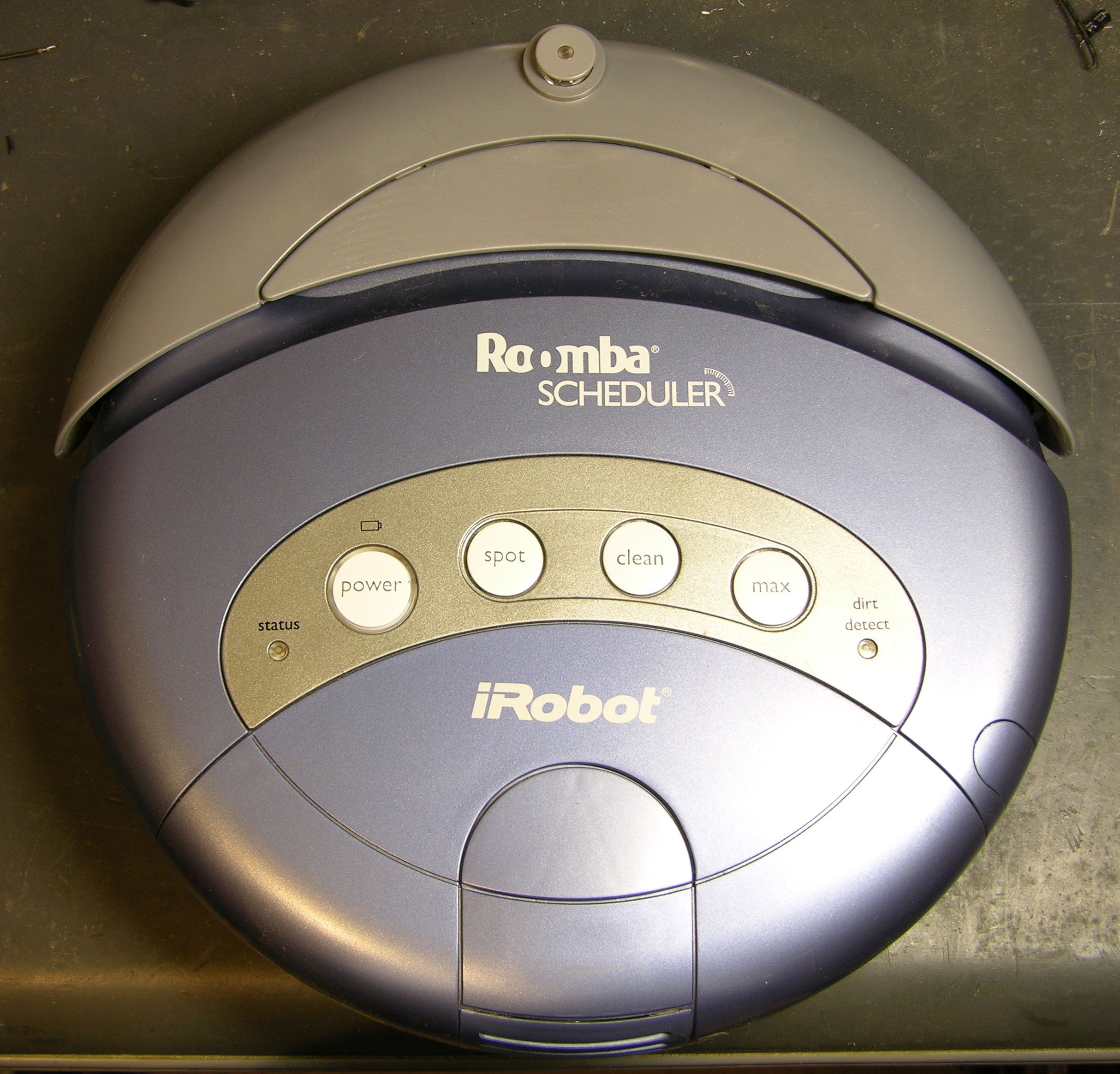
Over the holidays, I tried to fix my Roomba Scheduler. I ended up deciding not to try to trace from the battery connector to locate what part had shorted/burned when I connected a rebuilt battery with reverse polarity, I found an eBay seller with remanufactured main boards, and I ordered one for $20.

Refurbished Roomba Scheduler main board

Yesterday I had time to swap it out and get Roomba working again.

Board Replacement

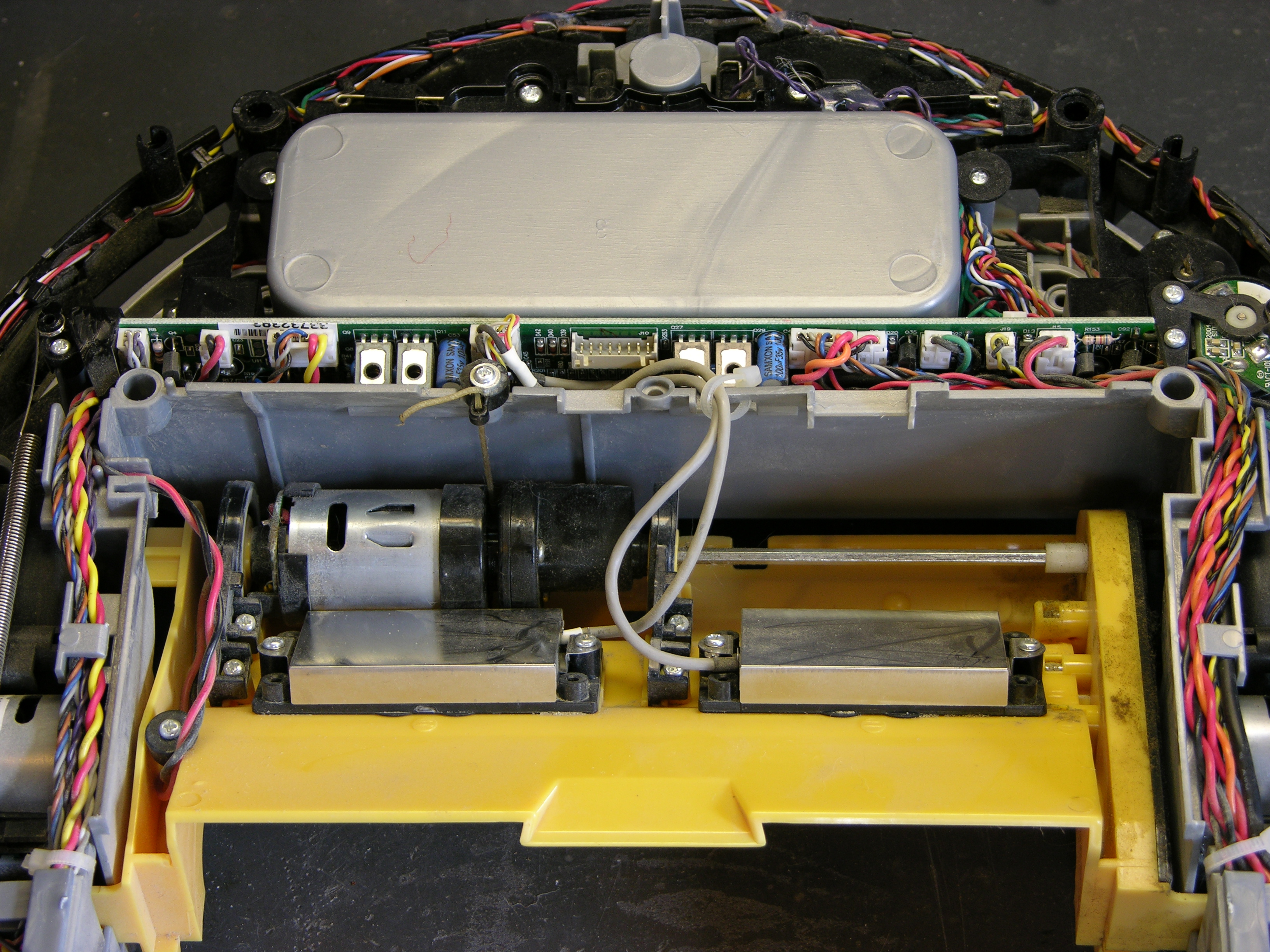
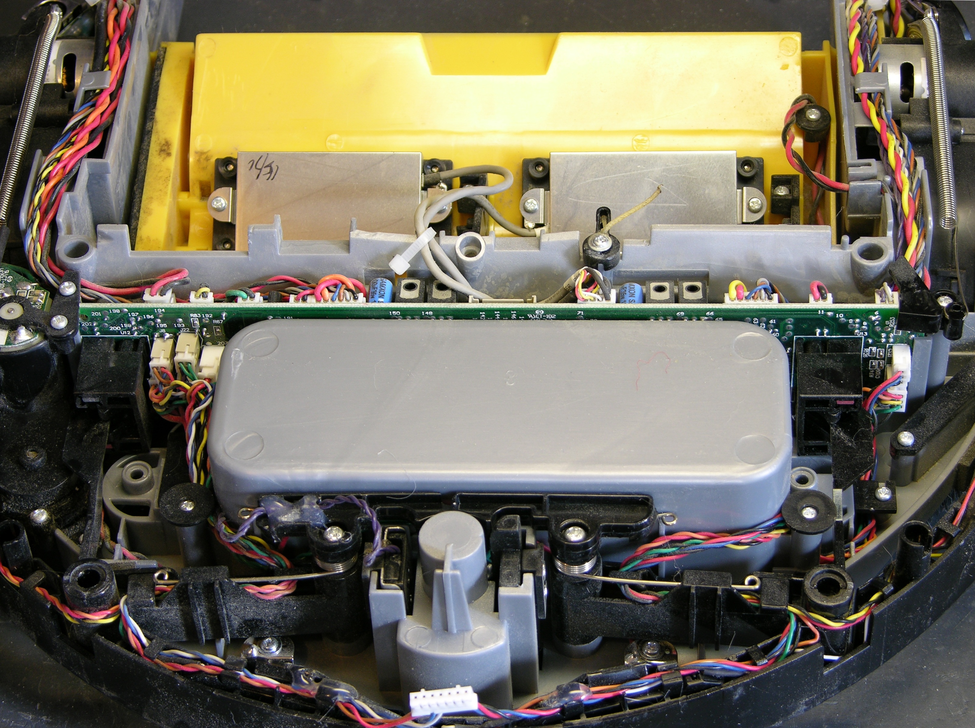
I had the new board completely mounted and half the connectors wired up when I noticed the first problem:

Original and replacement Roomba Scheduler main boards with different dirt sensor jacks

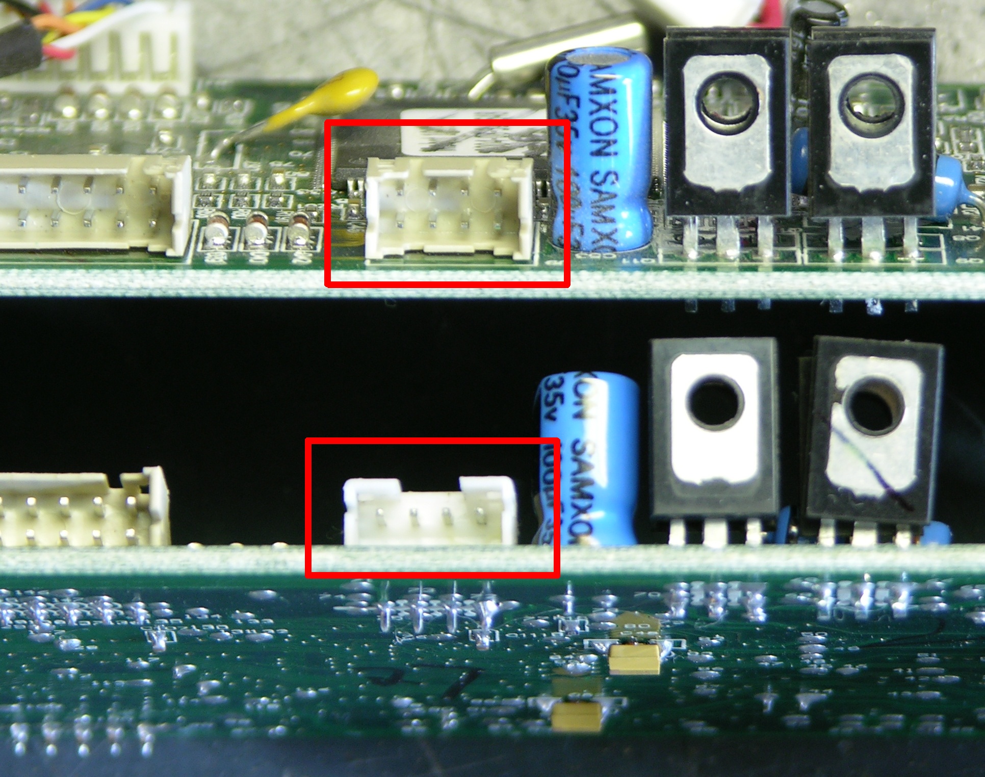
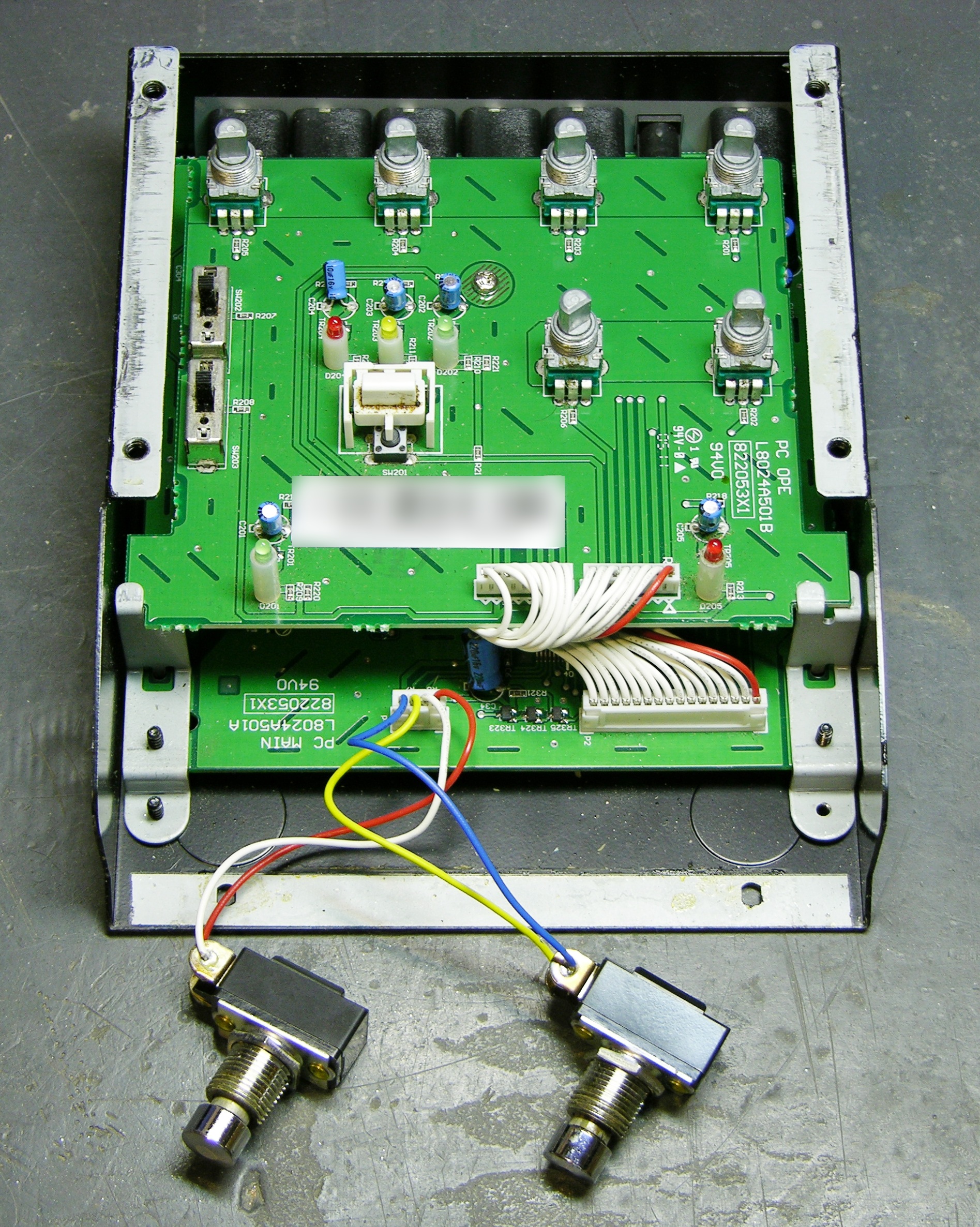
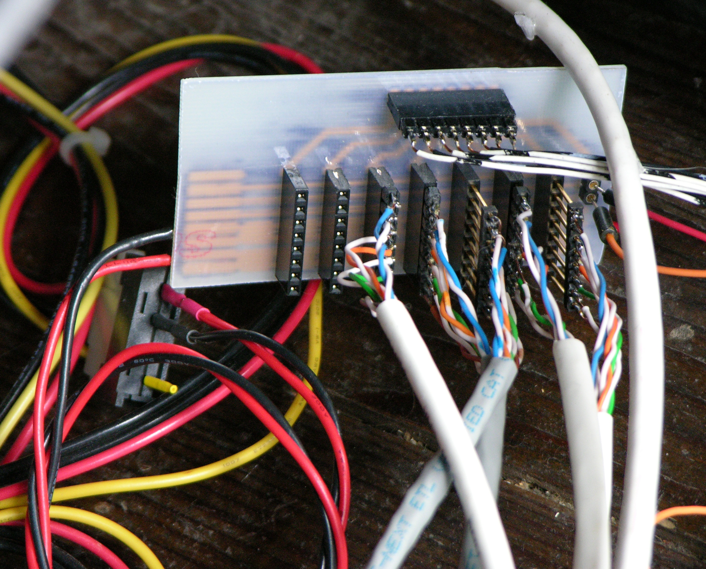
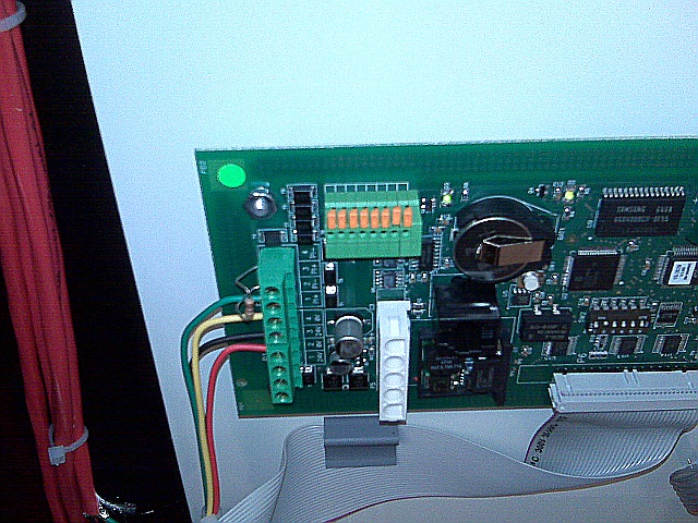
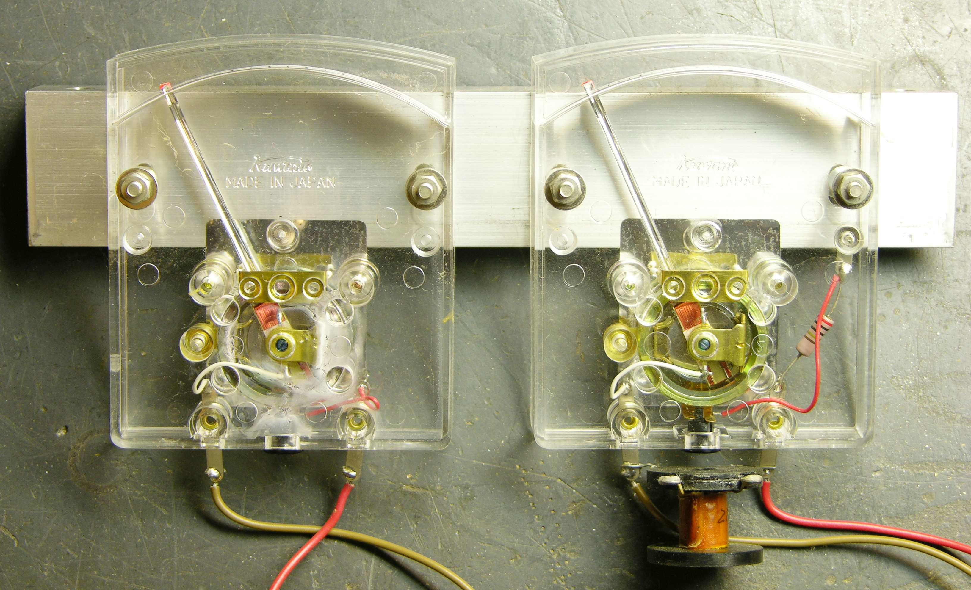
My Roomba has two dirt detectors, and J9 has two rows of pins, one row to each piezo assembly. The refurbed MB had a single-row J9, apparently from an earlier model with a single dirt detector.

I debated a bit about contacting the seller, but decided it was a waste of his time and mine to ask for a replacement board when I had everything I needed already at hand. I desoldered J9 from my original board (tedious heat-tug-heat-tug-heat-tug that demonstrates how good J9′s plastic is because it didn’t melt and how good the PCB is because the only thing I ruined was one of the test points), and had a much easier time desoldering the single-row J9 from the new board.

Roomba Scheduler main board with dirt sensor jack removed for replacement

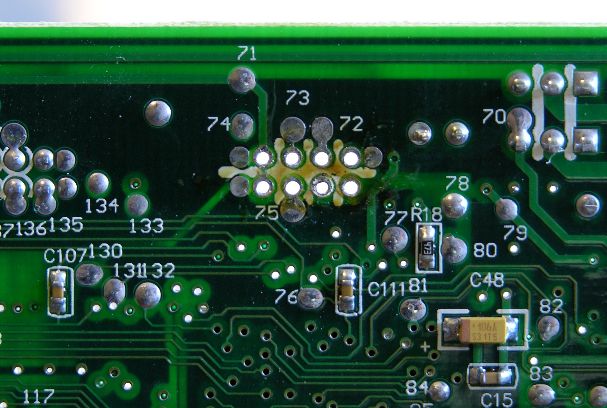
Then I got frustrated trying to get the solder out of the through holes. I had some success adding solder to the holes and applying solder wick, but there were three holes I just couldn’t get. Finally I gave up and pulled out the PCB drill bit set — a #68 bit spun gently by hand turns out to be just the ticket for cleaning the solder out of these holes. (Never again will I try to wick solder out of empty holes.)

Roomba Scheduler main board with dirt sensor jack replaced

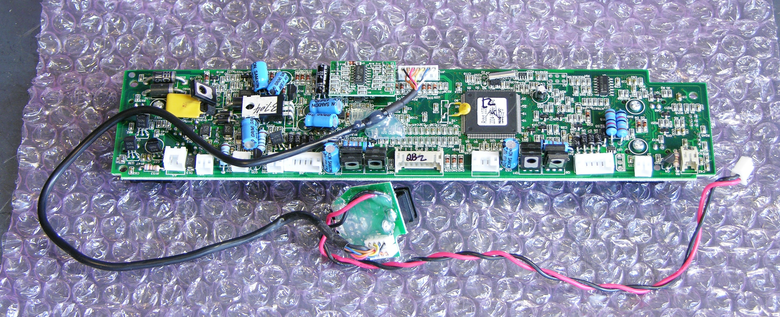
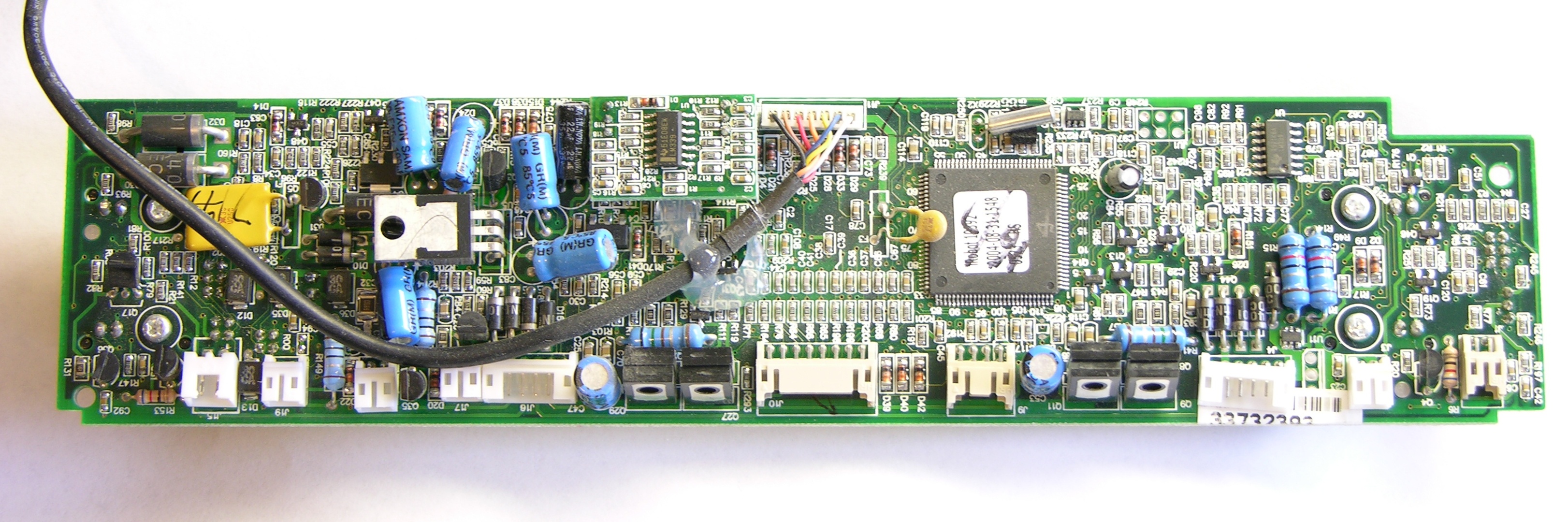
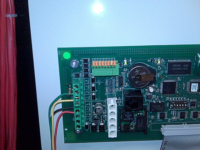
I cleaned the two-row jack’s leads with a wire brush, soldered it in, took a picture from an angle that looks like I still have the single-row jack in the board, and reassembled Roomba.

Attempt #1

I was delighted to see it turn on when I pressed the power button. I knew that should be what would happen, but it was still gratifying to see it actually happen.

Prematurely. Gratifying.

I took it to the living room to vacuum, hit Clean, and it just burped. It burped when I hit any button. Grrrr.

Diagnostics and Cliff Sensors

The first page I found when searching for why it was “burping” was What is Roomba saying to me?, which says that the “eh” sound means there’s a faulty cliff sensor.

I relocated the Roomba Discovery models’ diagnostic tests page and ran through the individual sensor diagnostics. On test 2, outer cliff sensors, only the starboard-most sensor worked properly; the outer port sensor showed “cliff” all the time. On test 3, both inner sensors showed “cliff” all the time.

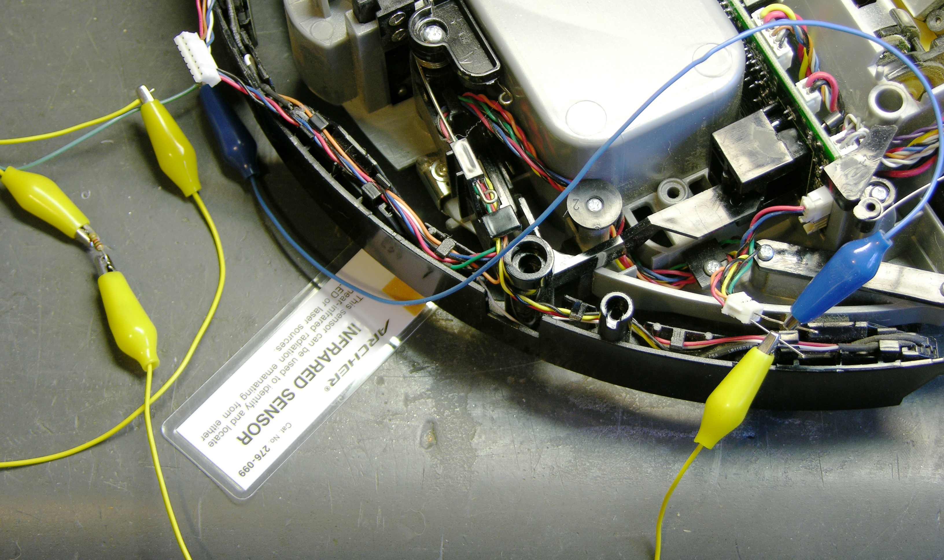
Gathering more test materials and retesting, I found that only the outer starboard sensor’s IR LED was lighting my infrared sensor card (apparently no longer sold at Radio Shack, but apparently formerly part number 276-099 and/or 276-1099), and the cliff-sensor IR LEDs were dark. Further, shining the virtual wall’s IR LED beacon into the cliff sensors caused the diagnostic LEDs to flicker, indicating that the cliff-sensor IR detectors (phototransistors or photodiodes) were working properly, so the problem definitely seemed to be in the LEDs.

Testing Roomba Scheduler cliff sensor IR LEDs

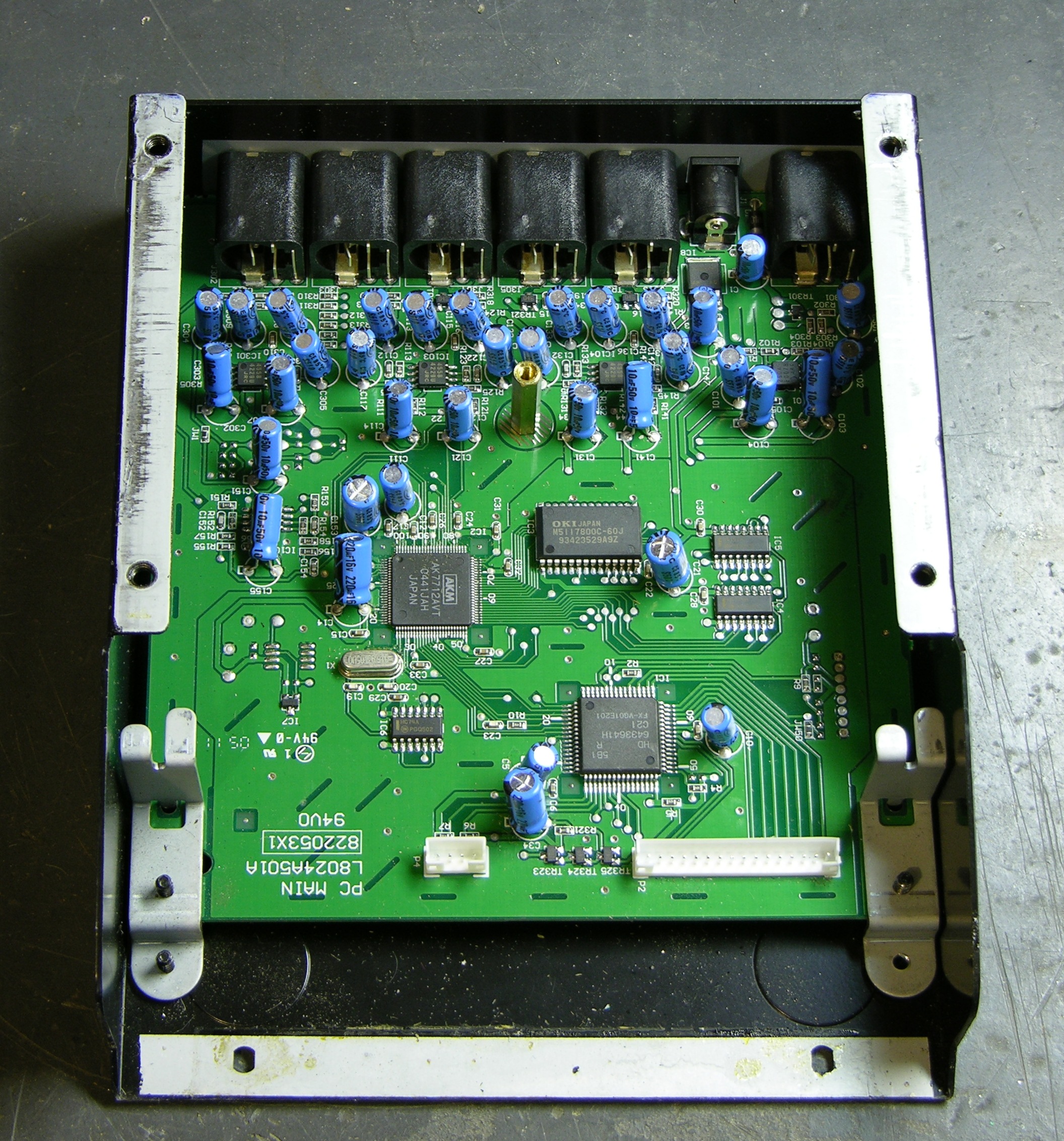
All three of the dark LEDs individually checked good with the diode tester on my multimeter. Tracing the cliff sensors’ LEDs, I found that the three dark ones were all powered in a single series circuit, fed by the red (anode) and orange (cathode) wires in the top row of J24 at the port end of the main board.

My meter’s diode tester didn’t use a high enough voltage to overcome the forward voltage drop of the series string, so I hooked my bench power supply to a 1KΩ resistor and the series chain. All the LEDs now glowed on my IR sensor card, so the LEDs weren’t faulty (which I had assumed anyway) — the problem was with the driver.

Robot Reviews Forum and Q4 LED Driver

Searching online for advice, I quickly found this forum post titled “Cliff sensor failure apart from one” complaining of exactly the same problem. “Gordon,” a very knowledgeable contributor, indicated that the dark LEDs were all driven by the same transistor, Q4.

I found Q4 on the board and it was twisted, so I straightened it without particularly thinking. (This fact isn’t relevant yet. Just wait.)

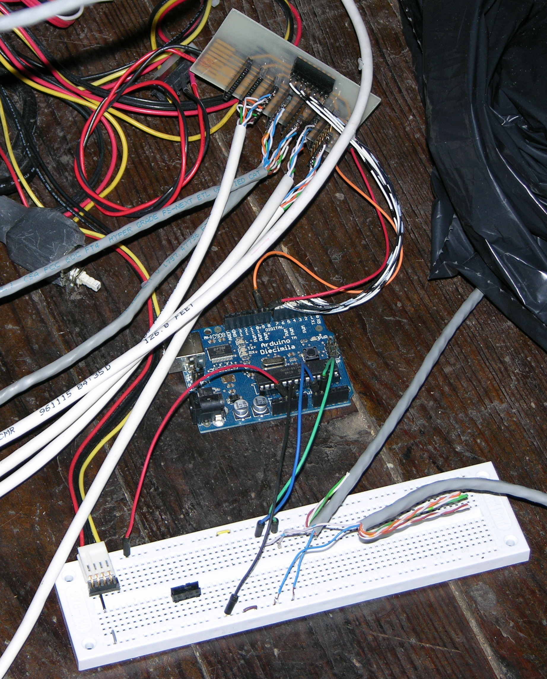
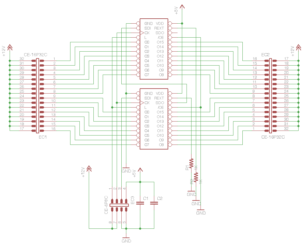
Gordon indicated which MB test points correspond to which Q4 pins, provided an apparently reverse-engineered and incredibly helpful schematic of the cliff-sensor LED drive system, and indicated that the Q4 and Q37 bases should have a 1kHz square wave on them, with a corresponding signal on the collectors.

I put the scope on Q4 and its base was oscillating nicely, but its collector stayed high. This made me suspect a faulty Q4, so I quickly and cleanly desoldered it and checked it in my out-of-circuit transistor tester. The tester said it was good with a β of about 220, which wasn’t what I wanted to see. I wanted it to be broken.

Transistor with detached leg

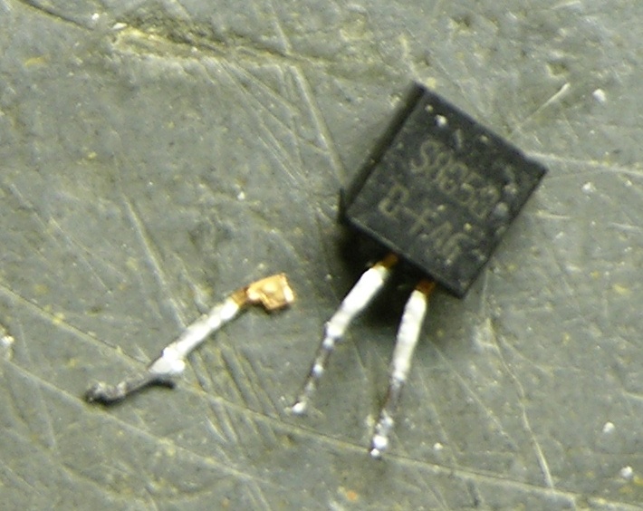
And then while I was straightening the leads and pondering what to do next, the emitter leg felt loose and I pulled it out with my fingers. Removed, it looked rather like a dessicated cricket leg you’d find in a corner.

Roomba Scheduler with replacement cliff sensor LED drive transistor Q4

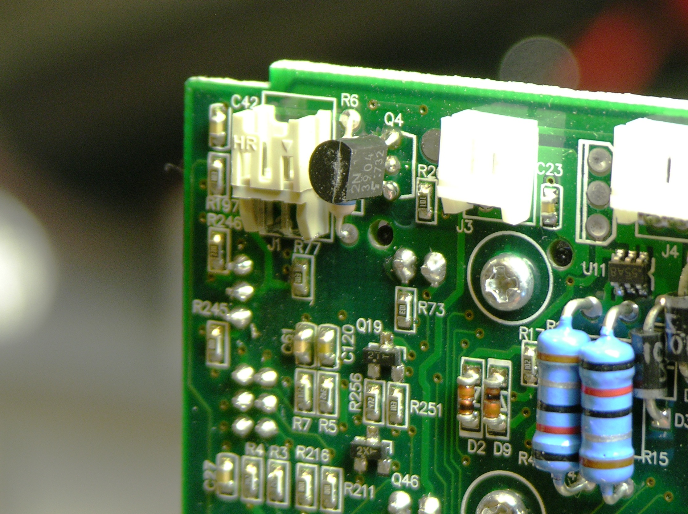
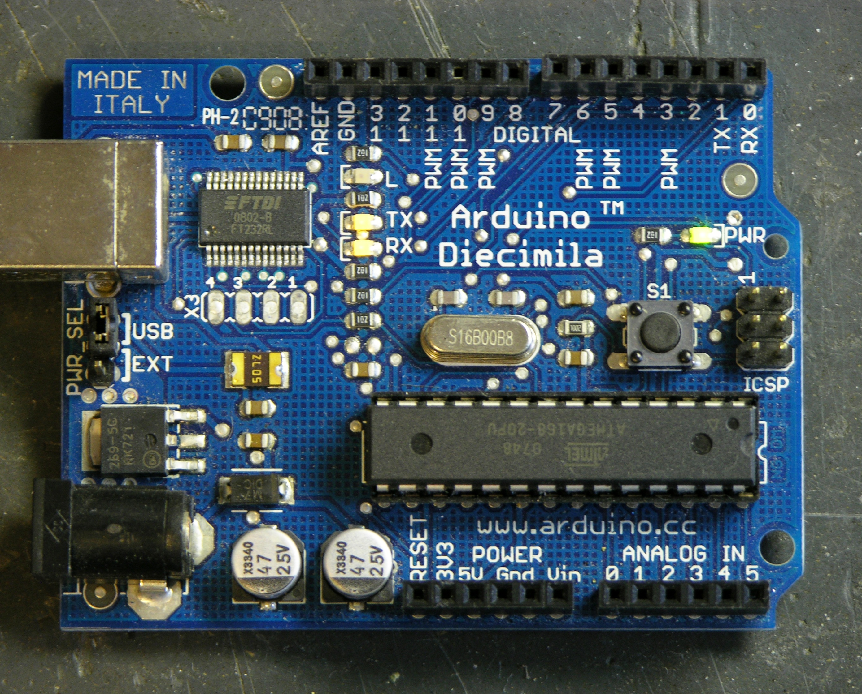
I don’t have SS8050s on hand (that I know of), but they’re all over the MB and appear to be used as general-purpose transistors. I found a 2N3904 with the same pinout in my parts bin (if you think all TO-92 transistors with the same part number have the same pinout, you haven’t shopped enough different manufacturers), tested about the same β, installed it, and the IR LEDs all glowed.

I could have pulled an SS8050 from my original MB, but (1) I wanted to keep it intact, and (2) I wanted to demonstrate that another transistor would work. And so it did!

Sweet, Sweet Success

Roomba Scheduler powered up and ready to run

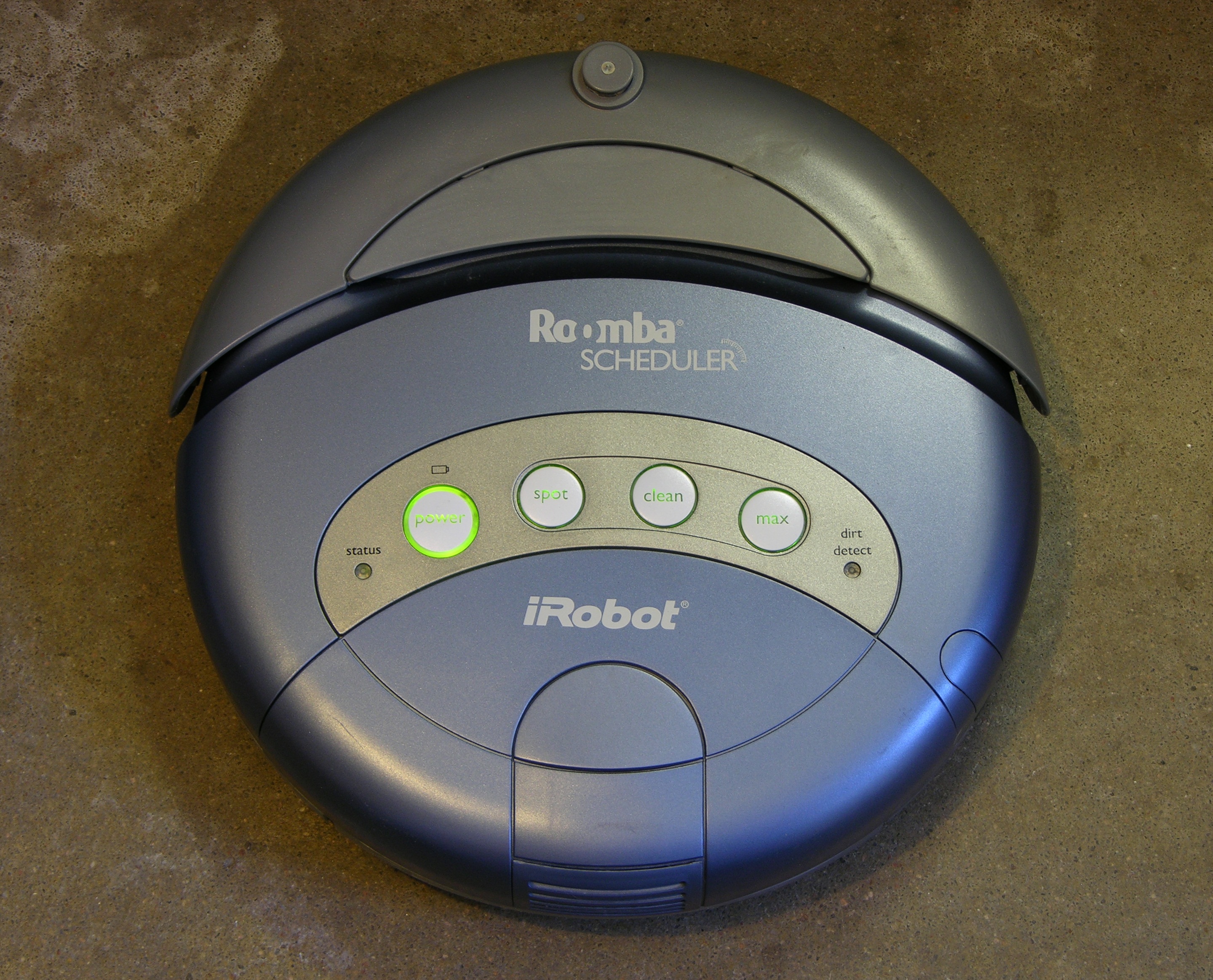
Roomba powered up again, but this time it didn’t burp (I mean “eh”) when I hit buttons, and it went straight into cleaning mode. Woo-hoo! I took it to the living room and let it clean, and it ran the course and picked up all the cat hair.

Today I emailed the eBay seller just to let him know what had happened. I wasn’t upset and I left him all positive feedback because the board he sold me fixed my problems within my abilities, plus I may have broken Q4 myself while straightening it, plus I had some fun tracing the problem. But I thought he should know what happened so he could check future boards more carefully for customers less fascinated by the process of repair.

He replied:

wow, yes you went above and beyond what I would expect. Thanks for helping out, i’m sorry you had to do so much.

sounds like the glass is half full with you.

There may be some truth to that.

Replacing a Dead Arduino FTDI USB-Serial Chip

January 19th, 2009 by Keith Neufeld

During the installation of “Organic Energy Cloud”, right after one of my fly wires turned bright red and dripped off the breadboard, I stopped being able to upload programs to the Arduino. As it was five minutes before the gallery opening, I didn’t want to take the time to replace the Arduino with a spare (that I’d had the foresight to bring along); and the Arduino was still operating with the last program I had loaded, which fortunately was sending a random twinkling pattern to the LEDs.

So I left it be and made a mental note to check it out later. Since the ATmega was still working but I had no communication with the board, I already had a guess that the FTDI FT232RL USB-serial chip was burned out. And I happened to have one on hand that I had ordered for testing LED puck USB control — which has been waiting for a year and can afford to wait a little longer.

Diagnostics

Arduino with broken FTDI FT232RL chip and TX and RX lights stuck on

I hooked it up this morning and found that the TX and RX LEDs stay on solid (which my CoolPix doesn’t capture well) — not a good sign.

Arduino IDE with no USB serial connection available

And the IDE’s serial port selection menu doesn’t list the USB serial connection as an option, further confirmation that the FTDI chip is toasty.

Removal

Removing SMT chips would be a great job for a hot air pencil. Since I don’t have one, I blobbed solder across all the leads on one side, then heated the solder mass with the iron while gently prying up that edge of the chip. It came up quickly and with little resistance, and I repeated the trick on the other side, then mopped up the excess solder with solder wick and brushed off the inevitable flux with rubbing alcohol.

Arduino Diecimila with FTDI FT232RL chip removed, closeup

I pulled the pads for pins 27 and 28 completely off the board, but they were unconnected and are for an optional 12MHz external oscillator not used in this design. I also noted the bridge between pads 25 and 26, but it appears to be by design — the pins are both tied to ground anyway, 25 being AGND and 26 being TEST that must be tied to ground for normal operation.

Replacement

I tried using the blob-and-drag method to solder the new chip in place, but ended up using the SparkFun blob-and-wick method instead.

Arduino with replaced FTDI FT232RL chip

After cleaning the flux again, the resulting board looks pretty reasonable (although I managed to get the chip on crooked, dang it). And the serial lights aren’t solid any more,

Arduino IDE with USB serial connection available and selected

and the board now shows up in the list of connection, and I can download programs to it again. Hoo-rah!

Fixing a Buzzing Clock Radio

December 31st, 2008 by Keith Neufeld

I’ve been using this clock radio for at least twenty-three years, and I love being able to read its huge 2″ digits when I wake up during the night and my eyes are blurry and unfocused. It’s having a little trouble here competing with the sunlight streaming in the side window, but it’s nice and bright at night when I need it.

Spartus clock radio

Lately it’s picked up an annoying habit of buzzing at, you guessed it, 60Hz. The intensity and timbre of the buzz vary, sometimes coming and going at the same time I can hear the furnace fan starting up and shutting down, sometimes apparently at random.

Listening carefully has led me to believe that the buzz isn’t coming from the speaker end of the clock, but rather from the power supply end. Speaker buzz would suggest bad filter capacitors (and one could certainly forgive twenty-five-year-old electrolytics for needing to be replaced); but power supply buzz makes me think of transformer windings coming loose and needing to be re-epoxied, metal brackets near the transformer working loose and needing to be tightened, and that sort of thing.

Today I had time to open it up and — I think — fix the problem.

Spartus clock radio, interior

Most of that is radio circuitry, and I don’t even use the radio. The clock part appears to be two ICs underneath the raised pushbutton circuit board. The transformer is in the “basement level” between the two posts to the left of the display’s ribbon cable.

Transformer with loose mounting screw

Right away I could see something I suspected was at least part of the problem. The transformer’s forward mounting tab was bent at other than the proper 90° angle from the body, only one edge of the mounting screw’s head was in contact with the tab, and there was a lot of slack between the tab and the mounting boss.

After removing the main PCB to make room to get a screwdriver in there and straightening the mounting tab with pliers, I got the screw tightened down properly. I could tell that the screw hadn’t worked loose over time but had been assembled this way at the factory: I could feel that I was tapping new threads into the mounting boss as I turned. Expecting the plastic to be fairly brittle after twenty-plus years, I worked gingerly, and successfully tightened the screw without breaking the plastic.

Transformer with loose crimped tab

While turning the screw, the entire end of the transformer’s cover was rocking from side to side, and a different angle revealed the reason and a second likely suspect for the buzzing sound (of which I carefully took this out-of-focus picture). The mounting cover had an edge bent out away from the laminated core and a loose tab.

After a little work tightening things with pliers and pressure, the cover seemed to be pretty well fastened. I checked the power supply electrolytics with my Capacitor Wizard since I had the clock open anyway, and they all tested good. I reassembled the clock, retesting for buzz several times along the way, and so far the buzz appears to have been banished.

The transformer problem was clearly a manufacturing defect; and it’s interesting to think that it took over twenty years to manifest itself. Here’s to the next twenty!

Cleaning (and Cleaning . . . and Cleaning) Akai Headrush E2

December 31st, 2008 by Keith Neufeld

I just bought an Akai Headrush E2 delay and looping effects pedal. It’s the box that the amazing KT Tunstall uses in her solo performances of “Black Horse and the Cherry Tree” to lay down her own rhythm and backing vocals before playing guitar and singing, all by herself. It’s a really slick setup.

Filthy Akai Headrush E2 Delay/Loop controller

I got a great deal on eBay — they retail for ~$200 and typically run about $150 on eBay, but I picked mine up for $76 missing the 9V power supply. It turned out to be an even better deal than I imagined, because the seller forgot to mention that the pedal came with a generous helping of organic matter, lovingly applied all over the pedal. This picture is after a preliminary 3x cleaning with Goo-Gone.

Not only was the case unsightly, but the foot switch action was dodgy as well, and that’s not easily cleaned from the outside. To really get the case clean, I wanted to get the panel loose of the controls so I could give it a good soak; to fix the buttons, I wanted to spray them with contact cleaner. I figured I may as well show off the inside while I had it open anyway.

Akai Headrush E2 Delay/Loop controller upper PC board

There’s the upper PC board. Note the filth that crept down onto the mode select pushbutton, and even the potentiometers:

Filthy Akai Headrush E2 Delay/Loop controller pushbutton

I had already got the outside of the lower case fairly clean, but wanted to clean the inside as well, so I went ahead and took both boards out. Here’s the lower PCB, where all the magic happens:

Akai Headrush E2 Delay/Loop controller lower PC board

I actually had a plan for dealing with the filth. Goo-Gone is great at softening and removing sticky adhesives like the remains of the world’s largest velcro strip the former owner had attached to the bottom of the pedal; but there’s no cleaner like Fantastik for removing the evils that men have done from arcade game control panels and (apparently) guitar/keyboard effects boxes.

I gave the top case about a ten-minute soak in Fantastik — I had already soaked and scrubbed in Goo-Gone three times, mind — and after the soak it literally rinsed completely clean under the faucet, with the tiny exception of a little bit of gunk still in one of the potentiometer mounting recesses. The foot switches left behind a pool of brown liquid (and I had only sprayed the mounting threads), the potentiometer knobs had white inset lines again, and the washers that I’d had to pry loose of the case with my knife were clean and shiny.

I also used an “acid brush” (dry, no cleaner) to knock the accumulated dust and grit loose of the PC boards around the base of every component that penetrates the top cover and get the boards nice and clean again.

The pushbutton foot switches aren’t quite sealed, and I was pretty sure I could see in to the inside along the solder lugs. I sprayed with wiper cleaner/lubricant, worked the switches a bunch of times, and repeated the spray/work process twice more. Shiny!

Akai Headrush E2 Delay/Loop controller pushbutton foot switches, cleaned

Same pedal reassembled about an hour later, with towel lint added for your viewing pleasure.

Akai Headrush E2 Delay/Loop controller, cleaned

And remember, folks, you can’t go around calling yourself anal-retentive if you don’t bother to align your fasteners.

Akai Headrush E2 Delay/Loop controller rear panel

The pedal now works perfectly — no more double-taps from switch bounce and missed taps from stickiness, etc.

It makes such a difference that before cleaning, I couldn’t understand the operating instructions (because the pedal didn’t seem to be doing what they seemed to be saying), and afterward they’re much more clear (although incomplete in failing to mention that it does not record while you’re tapping the tempo in delay mode, pity; and confusing, incomplete, and inaccurate in their description of looping mode operation; but who, bitter, me?).

Seriously, after an order of magnitude shorter time poking around than I had already done before cleaning, I feel pretty comfortable that I understand how to get it to do the things I want to do. Using the delay mode, I can now play a pretty passable rendition of the “Fly Like an Eagle” synthesizer intro. Wonder what to tackle next . . .

Trying to Repair Roomba Scheduler

December 29th, 2008 by Keith Neufeld

Roomba Scheduler

About two and a half years ago, I did something foolish in trusting the wiring instructions from a Roomba battery rebuild supplier and blew up my brand new Roomba Scheduler. Hasn’t worked since, because I wanted to see if I could find the problem and fix it myself before sending it back for factory service. Turns out I can’t (or at least haven’t), but the inside is interesting nevertheless.

Opening

Getting into the Scheduler is easier than getting into the first generation, mainly because it (almost) all comes apart with screws, instead of the (few) latching tabs in the original Roomba. These instructions on fixing the Roomba Discovery “Circle Dance” do a good job of showing the screw locations, although the site then goes on to describe processes specific to cleaning the wheels’ optical sensors that weren’t relevant to my problem.

The most important part that wasn’t obvious to me from the instructions is that the front bumper holds down the front edge of the top, so you must remove the bumper, even if you don’t need to work on the bumper area.

Guts and Wiring

Roomba Scheduler interior, dustbin side

Once the cover is off, the inside looks pretty tidy. As on the original Roomba, there’s one main board sandwiched between the battery compartment and the brush deck, and all the sensors and motors cable up to it.

Roomba Scheduler interior, battery side

I had to pull all the cables before I could get the board out, and most of the cables had only one place they’d logically plug back in, but I still took pictures to make sure I’d know how to put it back together again, shown here for the convenience of all the king’s horses and all the king’s men who might be trying this themselves at home.

Roomba Scheduler wiring cluster

Having removed all the cables, there’s still an optointerruptor at each end with a bumper lever latched into it. It took some prying to get those loose — port (left when in motion, right when facing it to work on it) side first, then pull the board itself loose of the starboard side.

Main Board

Roomba Scheduler motherboard, component side

And here’s my main board, with nothing that I can see wrong. No scorched components,

Roomba Scheduler motherboard, solder side

no scorched traces. Foo. (The battery connector is J7 on the solder side, in case you want to trace out from there and try to debug this for me.)

With the component spacing so tight on the board, and no obviously damaged components to investigate first, I didn’t feel like bothering to plug all the connections back in and trace battery voltage while the board was out of its little home. So I gave up (for now, anyway), contacted iRobot to ask about repair, and reassembled the Scheduler.

Reassembly

The most noteworthy thing about reassembly is getting the bumper’s port-end (I think) mounting bosses back into their mating holes. Do those first, then the starboard (I think) end of the bumper, then ease the rest of the port end the rest of the way on. Whichever end it is, do the posts first.

Dirt Sensors

The last thing to mention while we’re in here anyway is the dirt detectors. The second or third generation of Roomba introduced dirt detectors that are supposed to be able to tell when Roomba is actually picking up dirt, so it can spend more time vacuuming that area. I think my dirt typically has a fairly uniform distribution on my floor; but maybe some folks like to send Roomba out to clean up knocked-over flowerpots and whatnot.

Anyway, I’ve always wondered how it could tell when there was dirt — some fancy-schmancy optical sensor pointing at the floor??? — and here’s the answer.

Roomba Scheduler dirt detector piezo sensors

Piezo sensors. Dead simple. Dirt hits them, ting-ting pting tang, and they translate the sound / force into an electrical signal that the Roomba interprets as the influx of dirt. Brilliant!

Next

iRobot promises to respond to a customer inquiry within one business day of receipt, so . . . they’re late. But we’ll see what they say about repair service and cost. I understand they also sometimes have returns and refurbs available for purchase; and at the right price, that could get me a new Scheduler and leave me a spare for parts.

Hm, looks like entire used Schedulers are running ~$100 on eBay, and I just found someone selling the circuit boards for $20 plus shipping. I can’t imagine iRobot touching that price for a factory repair, so it looks like I may be able to do this myself after all. Maybe get a spare Scheduler just for the fun of it, too.

A6276 LED Controllers for “Organic Energy Cloud”

December 29th, 2008 by Keith Neufeld

My earlier edge-lit plexiglass demo was a study for an art/technology collaboration with Lisa Rundstrom that became known as “Organic Energy Cloud,” installed at Diver Studio for the November 28 Final Friday.

Lisa and I ended up agreeing on 200 LEDs (and ultimately installing 160). I had decided early on that I wanted to use two A6276 16-LED drivers to a board, for distributed LED control, all run by an Arduino. Once I got all my parts, over the November 22 weekend, I designed and began assembling the driver boards.

Schematic and Boards

A6276 32-LED driver schematic

The schematic is dead simple — daisy-chained A6276es, common clock and latch lines, output enable tied active (low). For speed and cost, I planned card-edge connectors to solder all the LED and “umbilical” connections to. Although the A6276 doesn’t have separate digital and analog grounds, I used separate wires in the umbilical for digital and LED V+, and I doubled the GND and LED V+ lines for current-carrying capacity.

Copper PCB with A6276 LED control boards milled

I hand-etched a prototype PCB to make sure the design worked, but it was pretty time-consuming and not my most beautiful work (especially being a two-sided board). Tom McGuire milled me a much more beautiful set of boards (although not using that mill), and did a very nice job using the drill holes as registration marks to line up the milling for the back side.

Assembly

Monday the 24th, I started pressing my friends into service for slave labor. Jeremy and Mindy were my first victims, and together we got all the PCBs and about half the LEDs assembled. Jeremy was stripping wire ends and Mindy and I were soldering — she did a fantastic job, especially for someone who had never soldered electronics before.

Soldering wires to SMT LEDs with clothespin vise

The key to retaining a shred of sanity while soldering wires onto SMT LEDs is a good soldering jig. Sunday night while assembling my prototype control board, I had tried to assemble LEDs with just the helping hands vise, and the LEDs kept going crooked in the alligator jaws. It took me about an hour to solder sixteen, and I knew that wouldn’t get 200 done in time.

I figured my mom still had some wooden clothespins, and after a little quality time on the disc sander, I had some perfectly elegant, incredibly functional SMT LED soldering jigs. Production speed skyrocketed; frustration plummeted; stabbiness dissipated.

Assembled 32-LED controller

With the LED wires attached, and especially once the umbilicals were on (not shown here), the controllers really reminded me of facehuggers.

Rather than try to size LED wires specifically for LED placement within the piece, we made them all the same length. Lawrence, Gail, and the kids (especially Phill and Jake) stayed up late the next night helping me finish soldering LEDs and assembling the controllers.

Bus

I designed the controllers so that the clock and data lines would run in parallel to every board, but each board would have a separate latch line. It doesn’t matter what’s in the A6276′s internal serial buffer — it only matters when that chip gets its buffer latched to the outputs — and this arrangement made for a minimum of connections to the Arduino.

I knew we were going to be plugging and unplugging the umbilicals from the Arduino multiple times before we got everything assembled; but because of the parallel bus arrangement, there were too many wires to plug the umbilicals directly into the Arduino’s headers. I thought about plugging the bus together on a breadboard, but it would have made for a lot of jumper wires for the paralleled lines.

Organic Energy Cloud bus

It ended up feeling easiest to design a small bus board with female headers on it, with the power, data, and clock lines bused, and the latch lines run to a separate 8-pin header at the top. (The bus board could run eight controllers — 256 LEDs — although we only ended up using five controllers.) I would have chosen to use ribbon cable to connect the latch header to the Arduino, except I forgot about that jumper and had to make something quickly out of borrowed wire while we were doing the gallery installation.

All Together

Because I was prepared to run 200 LEDs at ≥ 20mA each, the small power supplies I have weren’t going to be up to the task, and I used a PC power supply, not visible here except for its DC power cables.

Arduino and Organic Energy Cloud bus/wiring

The Arduino is plugged into the bus and the PC power supply, and in the foreground is a breadboard for a part of the project that didn’t come to fruition. This is actually how it sat during the show — Lisa is fascinated by technological infrastructure, and the mess of wires was part of the “organicness” of the piece. More on that in a follow-up post on the installation.

Controller Enhancements

32-LED controller, closeup

Soldering all the LED wires to the card-edge connectors turned out to be a bit of a chore with someone helping with two vises and a needlenose pliers, and incredibly tedious to do alone. All along, I’ve been thinking about how I could design or redesign the controllers so they’d be practical for artists to use without me there to assemble everything, and these boards just aren’t suitable. I have three crucial considerations that weren’t anywhere near met:

  • Wiring the LEDs to the board needs to be easy. (Soldering individual wires was time-consuming and hard to do alone.)
  • Replacement of burned-out LEDs needs to be easy. (Desoldering wires from the controller and resoldering new wires isn’t practical, especially once the board is installed in a piece.)
  • Replacement of burned-out boards needs to be easy. (Desoldering all the wires from a bad board would be a nightmare.)

So ideally I’m looking for a connector that would make it quick and easy to change individual connections on the LED side, and also quick and easy to change a whole batch of connections on the board side — like a daughtercard with an edge connector on the bottom and jacks for LED wires on the top.

Coincidentally, the week after the show, I was at Anixter’s Chicago facility evaluating replacement keycard door access control systems for work, and I found what looks like the perfect connector on the back side of some HID card readers. The connector has screw terminals on the top for the wires that go to the door strike, motion sensor, etc., and plugs on the bottom to snap the whole thing into the socket on the card reader. The guys from the lab told me they think it’s called a Phoenix or Buchanon connector, and kindly gave me one to take home!

Pluggable terminal strip, top side

Pluggable terminal strip, bottom side

Now I just need to spend some time going through about a hundred pages of the Digi-Key catalog to see whether they carry this, and maybe to see what else they have that’s similar and might be even better.

Meanwhile, this past weekend during a scheduled power outage in our computer room for some kill switch and fire suppression work, I found this connector (upper left) inside the fire alarm control panel. (BlackBerry camera + closeup == fuzzzzzzz . . .)

Fire suppression control panel with quick-release wire connectors

Fire suppression control panel with quick-release wire connectors

I really like the orange quick-release levers on this — it’d sure be handy for hooking up the wires in the first place (presuming, as with the screw terminals above, that one is using a large enough gauge of wire that one can clamp them and make good contact). I also love that the wires feed out the top of the connector instead of the side. But it doesn’t offer bulk plug action like the above Phoenix-or-Buchanon connector.

Especially if the two had the same pin spacing, maybe one could offer boards with choice of connector. I think I’d pick the quick-release connector for use in a project with only one or two controllers, and the two-level connector for use in a project with lots of controller boards.

More quality time with Digi-Key for me.

eBay “Misprinted” a Coupon and Won’t Honor Terms

November 18th, 2008 by Keith Neufeld

Not electronics; but it’s chic these days to dis on eBay, and hey, it’s my blog.

Just won an auction last night for another SAE A502 amp for $200 + $40 shipping (and that shipping cost is legit — every A502 I’ve bought has cost the same amount to ship), so it seemed like a perfect time to use my 10% off + free shipping coupon.

eBay coupon for 10% off plus free shipping

Except when I entered the coupon code on the checkout page, it didn’t take off the shipping. A close examination of the fine print shows that it doesn’t say anything about free shipping — but there it is in big letters at the top of the page!

Hm.

Transcript of my live eBay chat:

System
Initial Question/Comment: Other

08:52:47 SystemSystem
Thank you for contacting eBay Live Help!

08:52:47 SystemSystem
Please hold for the next available Live Help Agent.

08:53:32 SystemSystem
Mark L. has joined this session!

08:53:32 SystemSystem
Connected with Mark L.

08:53:32 AgentMark L.
Hello, thanks for waiting and welcome to eBay Live Help! My name is Mark. How may I help you?

08:54:24 Customerneufeld****
Hi! I got a message in my inbox that says “10% off coupon enclosed + free shipping.” I tried using the coupon last night to pay for an item I won, and it took 10% off the purchase price, but it didn’t adjust for free shipping. Could you clarify how that’s supposed to work?

08:54:42 AgentMark L.
Sure, I will help you with that.

08:55:32 AgentMark L.
Are you referring to the coupon that states 10% off on shipping from the purchase price?

08:56:30 Customerneufeld****
Well, I’m not sure how to describe it, other than to type in everything that’s on the coupon and in the text below. Is there any way you can look at what’s in my inbox?

08:57:18 Customerneufeld****
The graphical part of the coupon says “Free shipping on gifts they want,” then down below it says 10% off the purchase price of a single item. The coupon code is CHOLIDAYNOV2008.

08:57:48 AgentMark L.
I am sorry but that it was a mis-print on the coupon. We will be sending a new message to you that will state that the coupon had a mis-print and there was no discount on the shipping.

08:58:49 Customerneufeld****
That sounds an awful lot like false advertising to me — you can retroactively change something like that and not get in trouble?

08:59:07 AgentMark L.
I do understand that this can be upsetting.

08:59:42 Customerneufeld****
I’m just curious.

09:00:13 AgentMark L.
Have you already paid for the item?

09:00:17 Customerneufeld****
I mean, eBay is the 800-lb gorilla of online sales, and I recognize that I alone can’t change what you decided to do. But I’m honestly curious if that doesn’t fall under false advertising law.

09:00:43 Customerneufeld****
Haven’t paid yet — I contacted the seller and said I had a question about how to use a coupon, and I’d be back in touch with him today. He said no problem.

09:00:57 AgentMark L.
I am very sorry that you have to go through this.

09:01:13 AgentMark L.
However, the coupon will not be applied to get the free shipping on the item.

neufeld****
Well, that’s what I needed to know.

09:02:00 AgentMark L.
There is no need to worry about. We send several coupons on a random basis and I am confident that you will receive anther one so that you can enjoy the benefits of the coupon for your next purchase.

Obviously if eBay makes up it’s mind that it’s going to do something — legal or not — it takes more than one person to get them to change their mind. But at least I can have a little fun with the agent along the way.

X-Ray Control Panel???

November 16th, 2008 by Keith Neufeld

One of the electricians at work gave me a bunch of circuit boards from decommissioned equipment this week. It’s usually elevator stuff, so I hadn’t paid much attention to it other than to note the pretty colored wires.

XG controller panel, rear

The I was taking it out of my trunk to put into a “process later” pile when I noticed the front.

XG controller panel, front

“X-Ray.” 60kV tube voltage. “Fine focus.” Whaaaa???

Combined with the way all the front-panel switches and knobs are bent and broken off, I’m guessing this was in one of the laboratories, some unfortunate researcher accidentally stepped in front of the beam and mutated into a creature with superhuman strength, and in the resulting chaos demolished the equipment. Since it was destroyed, now I have it. Cool!

I went ahead and disassembled it tonight. Here’s a different view of the meters:

Edge-style panel meters

And there’s a big pile of connectors, resistors, and lovely wires on my workbench.

Cool Rotary Switches

Here are the two rotary switch assemblies. Their knobs were broken off and their shafts bent, so they’re not working terribly well, but I’ve improved them a little.

Rotary multi-position switches

They have circuit boards that are ganged together, with the inner shaft turning the back set of switches (of course) and the outer shaft turning the front set.

Rotary multi-position switches

The mechanics of the assemblies are fairly intricate. You can click the picture (as always) for the full-resolution version if you want to follow along.

Rotary multi-position switches, partially disassembled

Clockwise from the bottom:

Every switch position is a separate trace on the PCBs, with 24 positions on the wide assembly, 12 positions on the rear part of the narrow assembly, and two sets of 5 positions on the front part of the narrow assembly. A wiper on the plastic rotor connects the PCB’s inner ring trace to each outer pad in turn.

In the upper left, you can see how the limits of rotation are set by two discs with tabs sticking out, which bolt onto the head end of the (sub-)shaft. The discs’ tabs stop against a rear-pointing tab on the head-end mounting plate, which is on the underside in this picture.

Shown at the top, the rear portion of the narrow assembly is still in good condition. It was pretty gummed up, but a few sprays of silicone lubricant got it turning nicely. The PCBs are mounted on a set of multiple threaded rods, threaded spacers, and unthreaded spacers. The rotor’s detent action is provided by the wavy disc on the back side of the mounting plate, a ball bearing sitting in a hole in the plate, and a leaf spring on the front side of the plate.

In the upper right, the front portion of the narrow assembly is okay, but the outer shaft that used to rotate it was sheared off at the base (shown immediately below it).

I had to saw the front knob off the narrow assembly’s shaft to get the assembly apart and make part of it usable. You can see that the kob appears to have been threaded onto the end of the shaft; but with a vise and a pliers, I was unable to turn it loose. The shaft had been pretty badly bent anyway, so I have no hard feelings about having to saw it off.

Idea for Rotary Switches

So I’ve actually been looking for rotary switches like this, and thinking of trying to make some myself. This unfortunately is not the form factor I need, but it shows the idea is sound.

The high school robotics team has strict rules they have to play by, and one of them is that the joysticks used to control the robots in non-autonomous mode must work like PC joysticks (I think the PIC that runs their control panel is charging and timing an RC circuit to determine the joystick position) and cannot have any supplemental power.

This wouldn’t matter, except that the linearity of the joysticks they have is poor; and with (apparently) only 8-bit sampling, there’s not as much they can do programmatically to correct the linearity as they’d like. So it takes a bit of programming effort to eliminate drift when the stick is physically centered; and then when they start to move the stick, the robot lurches into action with not much fine control over low speeds, and at high speeds is pretty much just maxed out.

Of course I assume if it were my robot, I could correct most of that in programming. :-) Still, that’s a lot to ask of high-school kids who are already making amazing engineering accomplishments on a very tight timeline.

So Ron (of the fundraising concert, and father of the team captain) would like to figure out how to build a new joystick that abides by the letter and spirit of the rules but gives finer control over low speeds and has really significant jumps up to maximum speed only when you floor it. Obviously he wants pots with an S curve response (log taper in both directions from center), and he hasn’t been able to find that commercially, at least not that he could retrofit into a joystick.

His idea was to do it discretely — come up with some sort of switching action, then connect that to a resistor ladder. He could play with the resistor ladder to his heart’s content until he got something that “felt” right for the application — make it pluggable and let the kids swap resistors until they got a response curve they liked. And he wasn’t too worried about the robot lurching as the joystick went from step to step on the ladder — he feels that relatively few values would suffice.

If these 24-position rotary switches could fit into a joystick’s gimbal assembly, they’d be fantastic for that! Reserve the middle 3-4 positions for a broad center band to eliminate home-position drift, then have ten more positions in each direction for different speeds.

Except I’m pretty sure the gimbal assembly has little 3/4″-diameter pots right there on it, and these big PCB things just wouldn’t work. Feh.

I thought about etching my own PCBs to replace the wafers inside a couple of sacrificial pots, but I hadn’t figured out quite how to route all the wires out.

Open to suggestions here.

Radio and Video Stuff and Projects in Progress from Slim

November 16th, 2008 by Keith Neufeld

Last weekend, Lawrence and I went to Pittsburg to help Maeve clean almost the last of Slim’s stuff out the garage. Here are some of the first interesting items from the vanload we brought back. Some of this I’m keeping; some I’d love to place in a good home.

SWR and Power Meter

This is going to Cort.

Comet CD-270D SWR & Power Meter, front

Comet CD-270D SWR & Power Meter, rear

He writes:

I’d like the Comet SWR/Power meter… Yes, I have a MUCH MUCH better one now… But that was the one Slim and I did ALL of the early repeater stuff with. There’s a lot of sentimental value attached to it. I was having a HELL of a time trying to get reasonable readings. He showed up with that one day and it made life so much easier. It was one of those “gold standard” items for us for a number of years.

Antenna

Don’t know what kind, but that’s an F connector on the bottom. Yours if you want it — any offer that includes shipping cost will be accepted.

Antenna

TrunkLine Millenium Active Headend Combiner 95-AHC16

This combiner takes CATV signals that are already RF modulated and merges them onto a single feed. I believe this had never even been opened until I took these pics. Available claimed.

TrunkLine Millenium 95-AHC16 active headend combiner in box

TrunkLine Millenium 95-AHC16 active headend combiner, front

TrunkLine Millenium 95-AHC16 active headend combiner, upper rear

Datavideo Timebase Corrector

A card to go in a PC — as far as I can tell not even connecting to the bus for anything but power — to stabilize video sync before capture. By my estimation, a relic of bygone days, and available upon request claimed.

datavideo timebase corrector

Vidicon Tubes

Although I’d never actually seen them before, I recognized these pretty quickly as videocamera imaging tubes, and the labelling identifies them as Vidicon.

Box of Vidicon camera tubes

RCA 7735B Vidicon camera tube, side

RCA 7735B Vidicon camera tube, front

Available if there’s any interest:

Qty Condition Description
2 apparently new in plastic case RCA 7735B
2 not visibly damaged RCA 7735B in GE box
1 visibly worn but not visibly damaged RCA K1008 in GE styrofoam claimed
2 unopened 2AP1 in soft paper
Probably a CRT — keeping
1 unopened “2AP5 BLUE” in soft paper
Probably a CRT — keeping
1 unopened WA0EDA (?) in soft paper
1 “Was burnt in place (useable) [sic] Matsushita S4097 claimed
1 “Used / beam current varies” Hitachi 7735A used in box
1 face shattered RCA 7735A, loose
1 face edge cracked, something loose inside Ampex 4508, loose claimed

Speaker in Swivel-Mount Enclosure

Speaker in swivel-mount enclosure

Perfect prop for the next Brazil.

Slim’s Portable Powered Speaker

This is a cute little Slim-built powered speaker. That appears to be a PL-259 plug with the tip broken off on the front — I’m not sure what the logic was behind using that connector. I’m thinking I should replace the connector and hang this on the wall above the workbench.

Slim's portable powered speaker, front

Inside, a 9V battery clip and audio amp module.

Slim's portable powered speaker, interior

Glass Heating Plates

This looks like some kind of experiment. Electrically-heated glass plates, half assembled. Slim was very interested in optimizing PCB production; maybe this was a test for heating etchant? Maeve takes hot tea and was always looking for a way to keep the pot warm; maybe this was a test for a teapot pad?

Glass heating pad, front and back

Glass heating pad, backlit

HeathKit Programmable Wind Chimes

I just missed the HeathKit era and never had the opportunity to assemble one (although I have of course assembled other electronics from kits, just not HeathKit). Here’s an electronic “wind chime,” complete and completely unassembled. Wow.

HeathKit TD-1089 programmable wind chimes, unassembled

HeathKit TD-1089 programmable wind chimes assembly guide

I’m torn between the opportunity to finally build a HeathKit, and the desire to preserve this forever just as it is. :-)

Indicator Light Bezel

I love this! Wish I’d found more of them, but so far only the one. Er, two. Well, the one bezel that’s a two.

Lensed 2 bezel, front

Lensed 2 bezel, side

Lensed 2 bezel, lit

Salvaging a Pile of VCRs

November 10th, 2008 by Keith Neufeld

VCR mechanics, PCB, and wiring harnesses

A few weeks ago, I tore into a stack of dead VCRs, salvaging interesting parts, recycling a lot of metal and plastic, and intending to reduce the volume they consumed. Unfortunately, the resulting lesser volume has been mounded up on my workbench instead of neatly stacked in the garage.

The insides of VCRs are familiar to most tinkerers, but some of the bits are more interesting in bulk.

Read the rest of this entry »