ResQPOD Circulatory Enhancer Circuit

June 23rd, 2007 by Keith Neufeld

Back in May, I got this email from my friend J who works ER:

http://www.advancedcirculatory.com/CET/resqproduct.htm

I was at work last night and we had a code come in by ambulance. The Newton fire dept. now uses these when they code somebody. I saw that it had a circuit board and some LED’s and thought that you might be interested. It has been used but it I cleaned it up. Let me know if this is something that you want to take a look at.

“Code” is code blue, no respiration and no pulse. So J saved me a gizmo from a dead person, and “cleaned it up.” This is interesting. Wonder what it could be. I read the manufacturer’s web page and it doesn’t really enlighten me as to what kind of electronics are inside it.

I visit a few days later, and the gizmo looks like this:

ResQPOD

There’s a hole down the middle and a switch on the side. Turn on the switch and two red LEDs flash every six seconds. You plug the bottom end into a breathing mask and the top end into the CPR squeeze bag, and the lights tell you how often to squeeze for respiration for optimal (two-person) CPR timing.

A little bit of prying gets the case open, and the board pops right out.

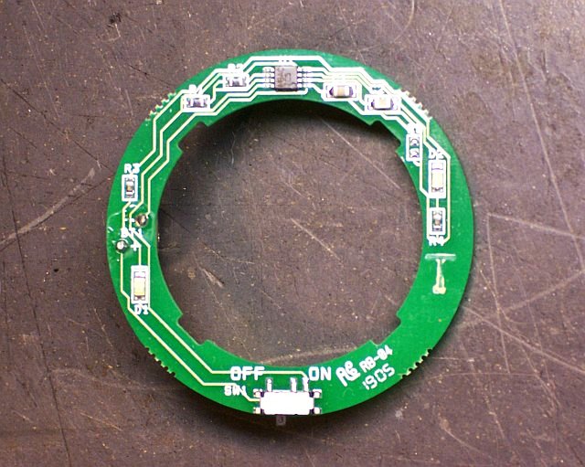
ResQPOD PCB

There’s not much to the circuit — the eight-pin chip is obviously what makes it work. My first thought is that it’s going to be a 555 timer, but it’s labelled “MBAC ZC5.” Google gets me nothing useful to identify the chip, so I draw out a copy of the PCB traces to see whether I can get anything out of the pinouts.

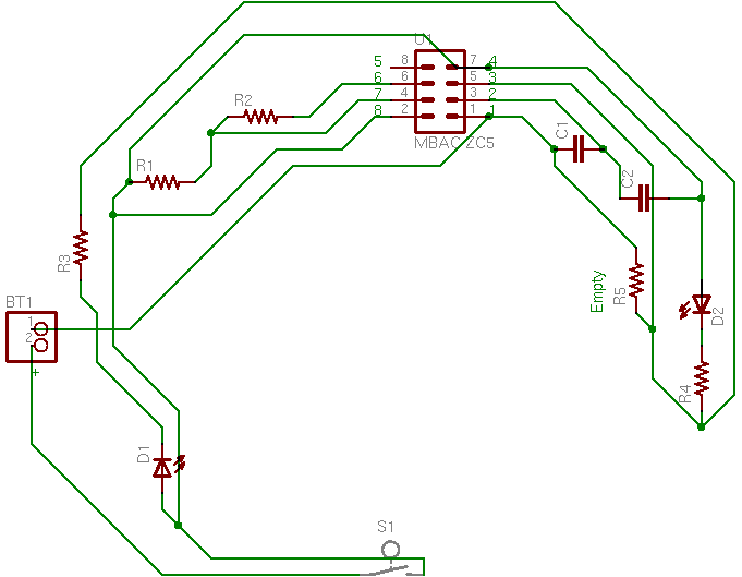
For my first pass, I place the components on the schematic corresponding with their physical placement on the board. (I actually did this on paper; when I translated to EAGLE, I didn’t have a library component for the mystery part, so I used a connector that had the pins numbered wrong. Heed the green numbers I added, not the grey ones.)

Schematic diagram of PCB in ResQPOD Circulatory Enhancer, PCB order

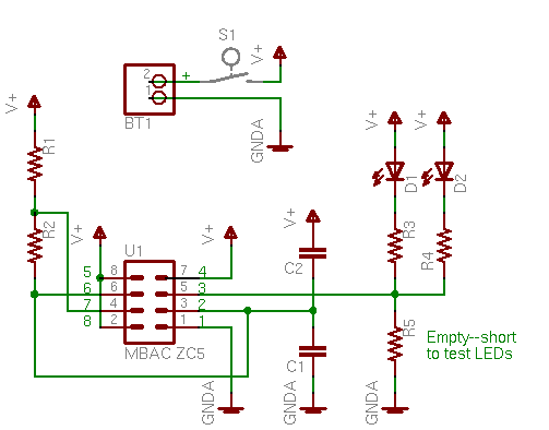
Then I slide things around based on a logical placement.

Schematic diagram of PCB in ResQPOD Circulatory Enhancer, logical order

And this is starting to look awfully familiar — it is indeed the same pinout as a 555 in the astable multivibrator configuration, which makes perfect sense. In fact, the 555 circuit should have a connection from pin 2 (TRIGGER) to pin 6 (THRESHOLD) that I haven’t drawn — and when I look closely, I can see that it’s hidden underneath the chip.

So now I have a tiny SMT 555, a couple of red SMT LEDs, and a handful of SMT passives, plus a cell that’ll probably drive this thing for a long time. Cool.

Adjusting an SAE A202 Amplifier DC Offset

June 23rd, 2007 by Keith Neufeld

As mentioned previously, I’m rather fond of SAE A502 amplifiers. Enough so that as I’m starting to think about biamping or triamping my system, I’ve started shopping for one or more A202 amps, the A502′s 100W little brother. And I found one on eBay, and it arrived this week.

Pop

I set it up in my stereo to drive the center channel speaker (for now), got everything connected, and turned it on. Pop. Turned it off. Pop. On. Pop. Speaker off. Pop. Speaker on. Pop. Amp off. Pop. No input signal at all, and pop pop pop.

SAE amplifiers don’t pop. They have relays specifically to keep startup and shutdown pops from making it to the speakers; so (I figured) I must have an unwanted DC component to my output. I ran this idea past Ron and he agreed that’s what was happening, so I measured the DC voltage at the speaker outputs with no input signal:

Channel DC Voltage Channel DC Voltage
Left -.64V Right -.05V

Huh. Looks like it’s time to adjust the DC offset.

Interestingly, I’m only using one amplifier channel for my center-channel speaker, and I happened to plug it into the left amp channel — the bad one. Had I plugged it into the right, I wouldn’t have noticed this problem for a long time, until I started using both channels. And that might have been when I set it up as a treble amp to drive tweeters, which might have blown out from the DC voltage. That would have made me cross.

DC Offset

Why is DC on a speaker output a bad thing? Well, each driver (the individual cone assemblies that mount in a box to form what we call a “speaker”) has an electromagnetic coil of wire in it. Current through the wire attracts and repels the back of the driver toward and away from a permanent magnet, causing the driver to move in and out, move air back and forth, and make sound.

The coil of wire also gets hot. The fine wire used in driver coils has a much higher resistance than the large wire between the amplifier and the speaker, so the coil is where the majority of the amplifier’s power is dissipated. Some of the amplifier’s electrical energy is turned into mechanical energy to move the driver, but much of it is turned into heat. Too much heat on a fine wire turns into a bad thing. And extra DC current doesn’t make sound; it just heats the wire.

Not much, to be sure. In my case,

.64V / 8Ω = .08A

.64V * .08A = .0512W

which isn’t much for my 150W speakers to handle. But it doesn’t do any good . . . and it pops when I turn the amp on and off.

This small DC output voltage comes about from an even smaller unwanted DC voltage in the preamplification stage, faithfully amplified through the power stage and delivered to the outputs. Because of imperfections in semiconductor manufacturing and the way preamplifiers are designed, this DC offset is virtually impossible to design out. Instead, preamp stages have a DC offset adjustment potentiometer, to adjust that particular preamp’s DC offset back to 0V (or very close).

Inside the A202

This morning I opened the A202 to make the adjustment. I was curious to see how much it looked like its big brother, and the answer is, not very much.

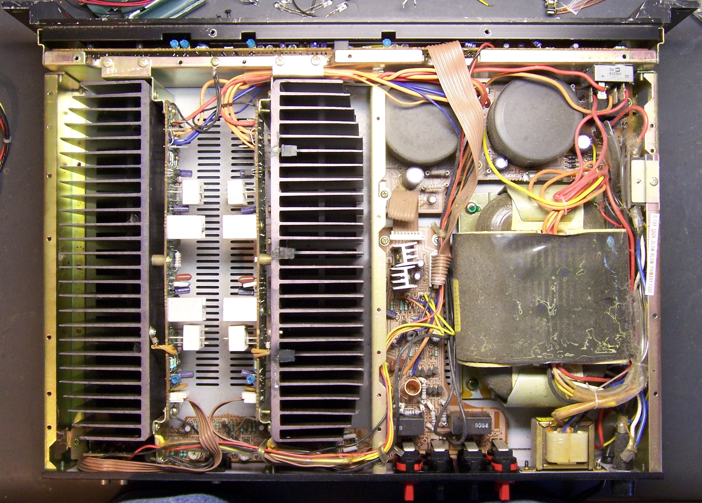
SAE A202 amplifier, interior

The power transformer is similar, and I recognize some other components and circuits, but the layout is completely different. This makes sense, given the smaller physical size of the A202, and its smaller power demands. The A202 is laid out asymmetrically, with power transistors on the amp’s right side (this picture is taken from the back, so our left) and the power supply on the amp’s left, rather than with the power supply sandwiched between two sets of power transistors.

SAE A202 preamp PCB

The preamplification stage is on this smaller PCB located at the back of the amp between the large heatsinks. The DC offset pots are clearly visible and easy to get to at the back edge of the amp. (Thank you!)

The speaker terminals (barely visible in the upper picture) are an odd design, rather than standard binding posts, and my voltmeter probes aren’t quite long enough to make contact. So I inserted wires into the speaker terminals and used gator clips to connect to the voltmeter. I powered up the amp and carefully turned the pots until the DC output was as small as I was able to get it. I was disappointed that I couldn’t get the right channel all the way to 0V (on my meter), but 5mV isn’t bad.

Channel DC Voltage Channel DC Voltage
Before Adjustment Left -.64V Right -.05V
After Adjustment Left .000V Right .005V

I actually first made the adjustment with the amplifier cold, and then realized how silly that was. After letting it warm up for twenty minutes or so, one channel had already drifted up to .025V, so I was glad to have remembered to go back and fix it.

Cosmetics

Any time you perform service work, you should always clean whatever you’re servicing to the best of your ability; it makes a huge difference to the customer’s perception of your work (even if the customer is you). Ron cleans and polishes VCRs he repairs; good auto mechanics clean the entire area around whatever they’ve replaced (and run your car through a car wash if they’re really clever), and I wipe down cases of PCs I repair for friends and family.

This amp was no different. The inside was full of dust, so I took it to my brother’s house and used his air compressor to blow it out.

SAE A202 amplifier with scratched case

The outside was more interesting. I don’t know what the former owner did with this amp, but the case looks like it had a fight with a parking lot and lost. Lots of dings, nicks, and scrapes.

I felt around the edge of the front panel for any dings with sharp edges, and carefully filed them flush with a fine file. Then I use a black permanent marker to fill in every shiny spot. It’s not a perfect match for the original finish and you can easily tell the difference from up close — but you can’t tell the difference from across the room in a normal listening position, and that’s well worth the effort.

About half of the model number on the front panel is scraped off, and I’m not sure how to repair that. It’s white (or near-white) paint, probably silk-screened on, and I think I’m more likely to make a mess than an improvement. I’d welcome experienced suggestions on how to touch that up.

Putting It All Together

I reassembled the amp and reinstalled it, and the popping sound is gone. Even with my ear directly in front of the speaker, I don’t hear any noise there — just the relay clicking in the amp itself.

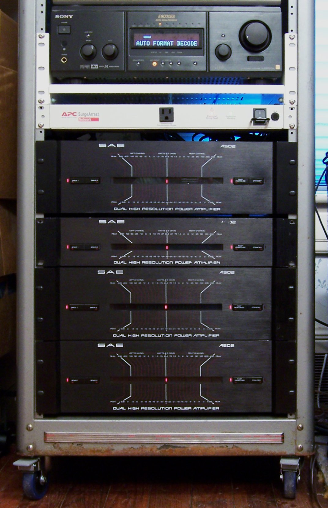
Here’s what my stack looks like now. It’s in an old PA cabinet on which I mounted soft-wheeled castors for convenience and to protect my softwood floor. The cabinet has rack rails, but the amps aren’t mounted — just stacked. I need to get nylon shoulder washers to protect the amps’ front-panel finish before I’m willing to rackmount them.

My stereo rack, with Sony preamp and SAE amplifier stack

From top to bottom,

  • my Sony surround processor / preamp sitting on a rack shelf
  • a rackmount, surge-protected power strip (love this!)
  • my original A502 amp, running the main speakers
  • the A202, running the center speaker
  • the A502 with replaced relay, running the rear speakers
  • another A502 that I bought working, running the subwoofer

I have two more broken A502s waiting to be repaired, plus a couple of other related projects, so there should hopefully be more along these lines soon.

Replacing an SAE A502 Amplifier Speaker Relay

June 23rd, 2007 by Keith Neufeld

In the late ’80s, almost certainly 1988, I used some of the money from my summer job to order an SAE (Scientific Audio Electronics; no longer in business) A502 amplifier from the DAK (Drew Alan Kaplan; no longer in business) mail-order catalog. The A502 is a two-channel solid-state audio amp rated for 200W per channel — but it’s as heavy as a tank (40-50 lbs) and actually able to live up to the promised wattage, unlike many smaller amps and modern receivers. At a comfortable listening level, the volume meter LEDs don’t even flicker on.

I’ve kept the amp and used it on and off since then, using it continuously for casual listening and home theater movie-watching for the last thirteen years. It’s never given me any trouble, and it performs admirably.

So admirably, in fact, that I’ve been shopping for more on eBay. In late December 2005, I bought two advertised as partially working; and this May, I finally repaired the first of them.

Replacing the SAE A502 Speaker Relay

The first of the two amps was advertised as having both A and B speakers work on the right channel, but only the B speaker work on the left channel. When I received it, I hooked up speakers to confirm the symptoms, then opened the amp to look around. The problem was immediately apparent:

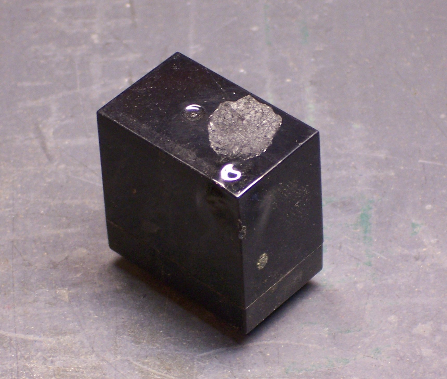
Speaker relay with melted case

Transient currents can generate popping and other unpleasant noises when a power amplifier is turned on. SAE designed around that problem by inserting relays between the output transistors and the speaker jacks, with delayed activation. Power on the amp, 2, 3, CLICK, and the speakers are engaged. Plenty of the time for the transients to disappear. And it works — my speakers are dead silent when turning the amp on and off.

Well, it works until one of the relays gets a little, um, melty.

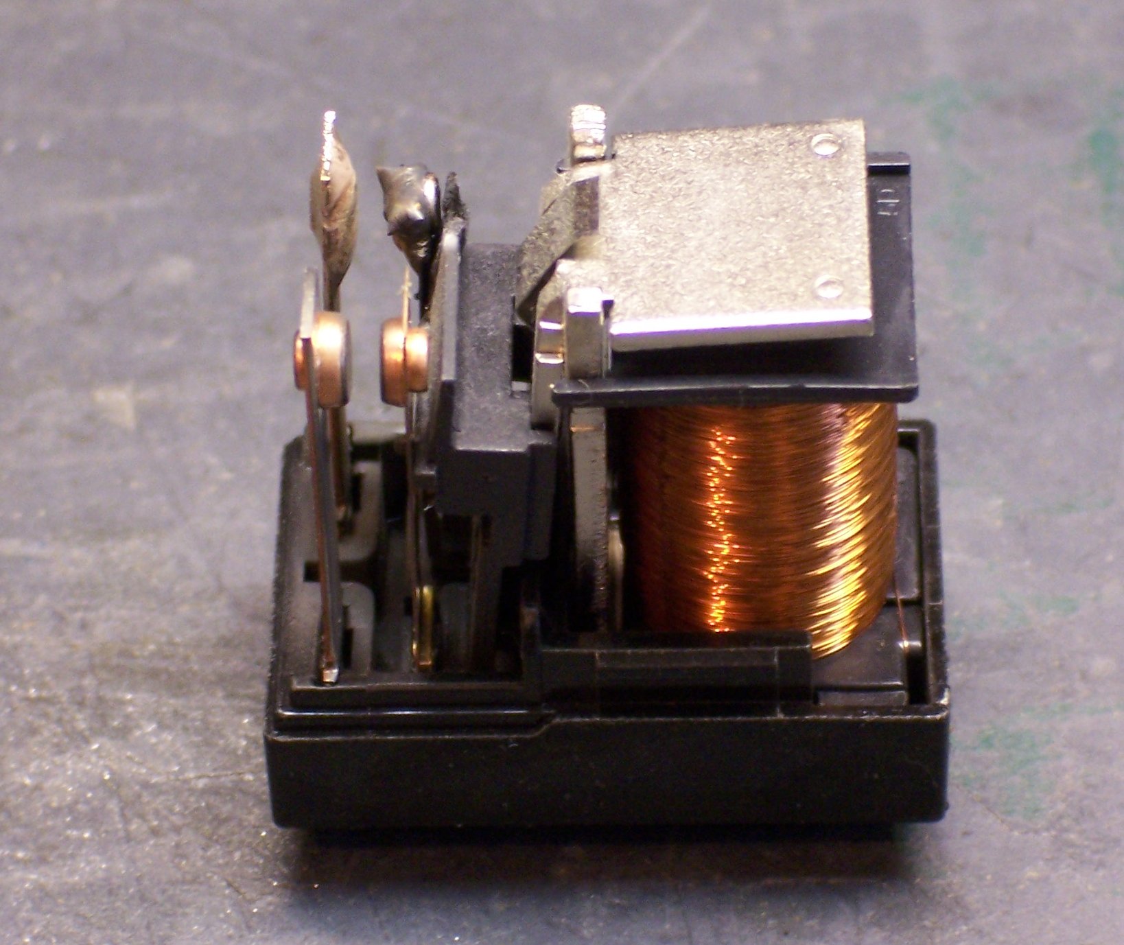
Speaker relay with melted contacts

I have no idea what happened to vaporize the contact, but I bet it was impressive. :-) [Ron Tozier, local TV and electronics repair wizard, suggests that the contact was probably slightly oxidized, and the extra resistance led to heat buildup and eventual catastrophic breakdown.]
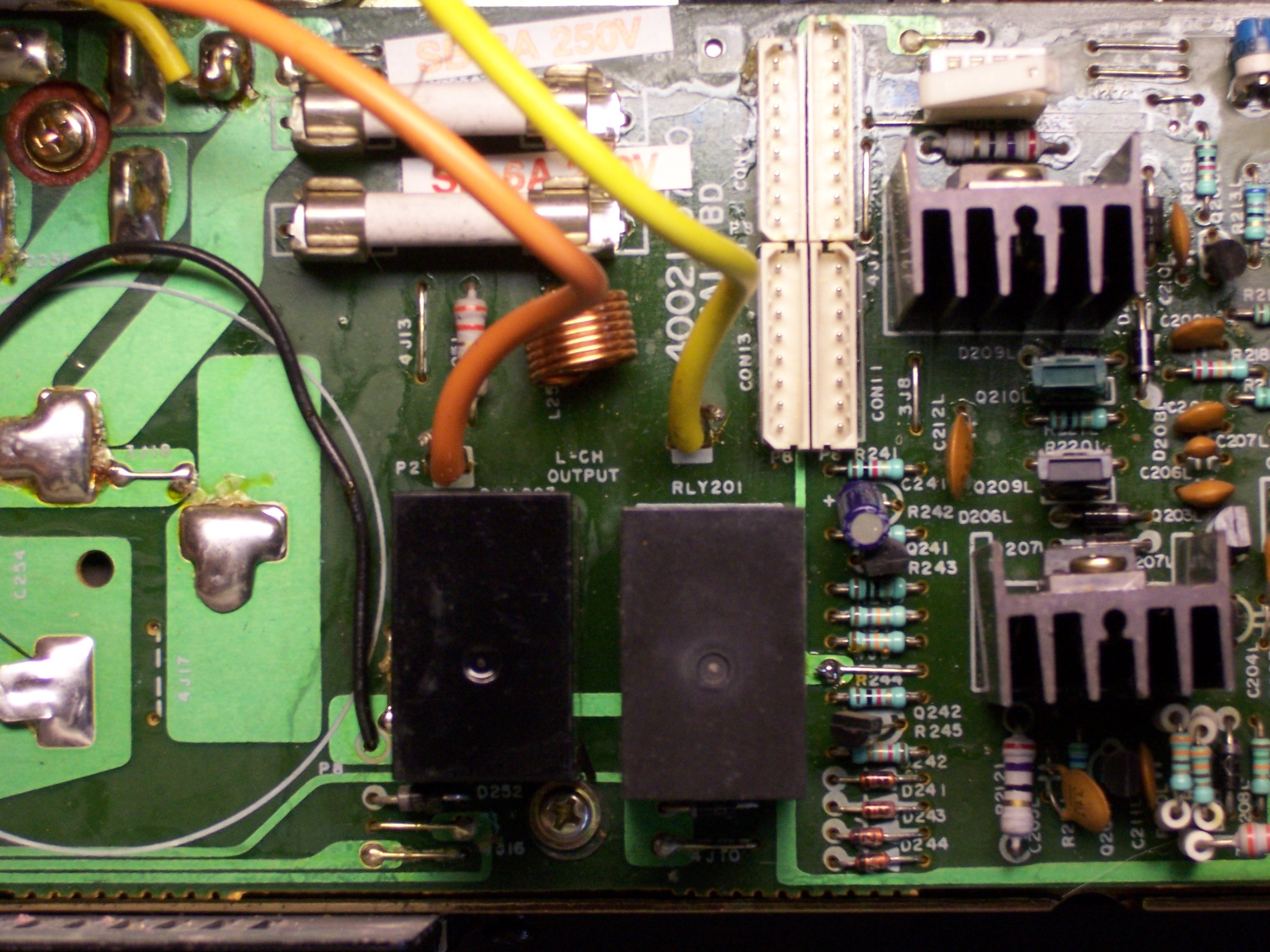
Now, although the relay is DPST, the amplifier circuit uses both contacts in parallel. So in theory, I could have cleaned the slag off the melted contact to make sure it stayed out of the way, polished the remaining contact, and resumed operation.

I really wasn’t comfortable with that idea, though. SAE put DPST relays in there for a reason, and I wasn’t really interested in changing their design. So I looked for a replacement relay, with no success. Google found me nothing to match the Matsushita part number, Digi-Key had no matches, and searching online surplus catalogs didn’t get me anything that matched the coil and current specifications with even close to the same form factor. So I set the amp aside until I could find a replacement relay, and kept searching occasionally.

At Last, a Relay

This April, after over a year of fruitless searching, I checked Digi-Key again, and they had the relay listed! Unfortunately, they had a minimum order of something like 108 pieces, and I didn’t need to fix 108 amps. Fortunately, one of their techs was able to cross-reference the relay, and in short order I had a bagful of perfect replacements. (I know, I don’t need to fix a bag of amps — but being prepared to replace another relay at some point in the future is worth a few extra bucks not to have to track them down again.)

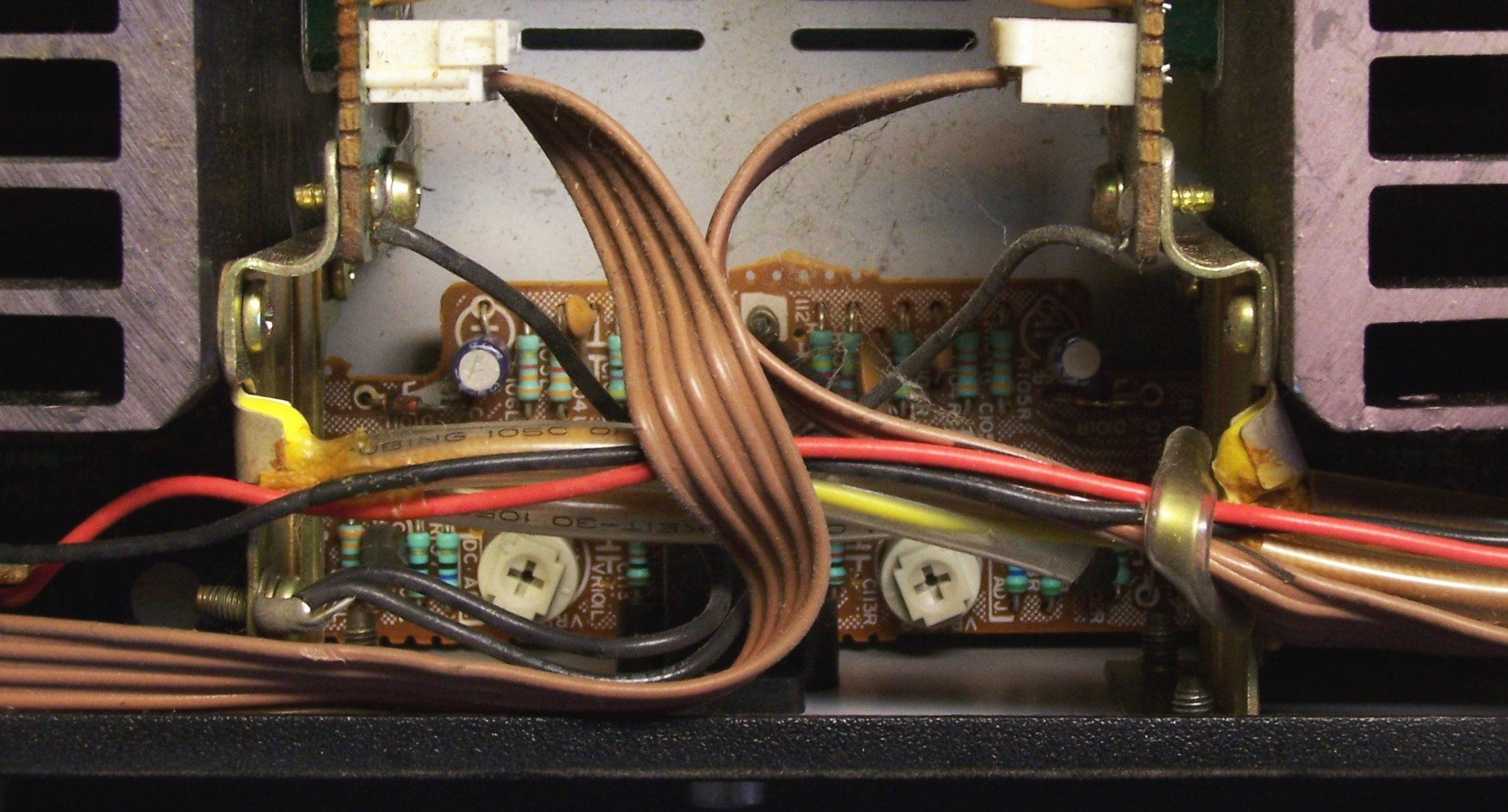
The board is a pain to take out because it’s bolted down to greased heatsinks, it has huge power-filtering capacitors mounted on the back side, and its cables are bundled such that they’re too short to pull the board out. Bleah! But after dealing with the mechanical issues, it was only a few minutes work to remove the old relay and solder in the replacement.

SAE A502 PCB with replaced speaker relay

The new relay (installed as RLY201, the right one) has a matte finish whereas the original was shiny, and its body sits a little lower with respect to its contacts, but those are insignificant issues. It fits, and that’s what counts.

The silk-screened circle to the left of the relays, BTW, is the footprint of the filter capacitor on the other side of the board.

Test Driving the New Relay

I threaded the board back into position in the chassis, bolted it back into place, and made sure the wires were all routed appropriately; but I didn’t close the case yet, as I wanted to test the new relay first. I plugged the amp into a power strip that was switched off, switched on the power strip, pushed the “On” button on the front panel, and POP! There was a moderately loud bang and a moderately bright flash, and I shut off the amp and the power strip quickly to have a look.

Strangely, the flash came from the right rear of the chassis — the opposite side from where I had replaced the relay. More strangely, I couldn’t find anything scorched or missing. I figured surely I’d see an electrolytic cap with its top blown off, or a resistor or diode vaporized, but nothing appeared wrong. I unmounted the board and checked the bottom side for brown scorch marks, but nothing wrong was visible there either.

My guess was that after the amp had been off for a year, some component got “tired” and the inrush current destroyed it; but even with repeated checking, I couldn’t find anything amiss. I found a copy of the schematic online and studied it in detail, but didn’t gain any new insight. I was reluctant to power up the amp and start poking around with a scope, for fear that the (hypothetical) broken component might lead to cascading, more expensive failures.

Testing the Repaired, Exploding Amp

Finally, I took the amp to visit Ron and ask his advice. I found his method of testing rather ingenious. This amp has 8A slow-blow fuses between the power supply and the power amplification section, not just a fuse on the line cord. We pulled all the 8A fuses and replaced them a pair at a time with 1A fuses, so we were powering up only one channel at a time. Anything seriously wrong would blow the 1A fuses pretty quickly, hopefully without doing further damage to the rest of the circuit.

After doing a quick check of the major capacitors and power transistors, Ron put an oscilloscope on the speaker outputs and I powered up the left channel — the one whose relay I had replaced. The scope stayed flat as it should — no unwanted DC component. Ron touched the line-level input, and we saw a low-amplitude 60Hz signal on the scope. All as expected.

Next, I pulled the fuses from the left channel and moved them to the right, where I had seen something blow up. Ron moved the scope and we powered up. The left channel output was flat as well — good so far. Ron touched the input, and we saw the same amplitude 60Hz signal on the scope.

Hey . . . what?! It works???

Well, yeah, it does. We couldn’t find anything wrong. I put the 8A fuses back in, took it home, reassembled the case and put it into my stereo, and it’s been running my surround speakers for a couple of weeks. Nary a problem since that day.

So what were the pop and the flash when I powered it back on? My best guess is that some piece of crud (dust bunny, cat fur, etc.) got shorted across a couple of high-voltage pads and lit up when the voltage said hello. Cort says he saw that happen a lot when he was repairing dusty arcade games back in the day.

One down, some more to go!

Farewell to Slim

June 11th, 2007 by Keith Neufeld

My friend Rolland “Slim” Cummings passed away of a heart attack this afternoon. He was the director of Instructional Media at Pittsburg State University. His wife Maeve is a professor in the PSU College of Business and the coauthor of a best-selling MIS textbook for which I rewrote the networking chapter.

Slim built the video distribution network at PSU, including a video switcher of his own design and construction, to route TV channels and videotapes to individual classrooms. He was active in amateur radio and electronic design, and was a close friend of the late Jack Buffington and mentor to his son and my good friend, Cort. Slim was always the one to test every option or method, not settling for good enough, but insisting on finding the best.

He was also opinionated and bullheaded, and could hold a grudge for years. Long before I knew him, he and Maeve had an Apple Computer dealership. Something happened to sour that relationship; and much later, when Slim gave me a couple of sticks of surplus RAM, he said he wouldn’t have given them to me if he’d realized I was going to put them into a Mac. But he showed respect with equal intensity when he was treated fairly, as I saw time and time again when I worked with him at the university.

Slim was generous with his knowledge and his resources. He spent a lifetime collecting electronics supplies and surplus, and he was always ready to share them when they were needed. He slowed down several years ago and had started cleaning house and discarding old equipment, sending carloads of mostly junk home with me. My bench power supply, my function generator, my gigantic bare copper PC board, and the panel meter I used in my battery meter project are just a few of many supplies Slim gave me.

I last saw Slim just over two weeks ago, on a rare trip back to Pittsburg for an unrelated conference at the university. I joined Cort for a visit up to Instructional Media, and we helped Slim haul equipment to the pile for the annual university surplus auction (and ourselves left with another trunkload). Just this weekend, I emailed Slim to ask about a giant heatsink I’d given him a few years ago as a bit of a joke, and he said I was welcome to it; was I going to be back that way or should he ship it?

I wish I’d been able to go back to pick it up from him myself.

CNC Drill Sled

May 6th, 2007 by Keith Neufeld

CNC drill sled, lower left view

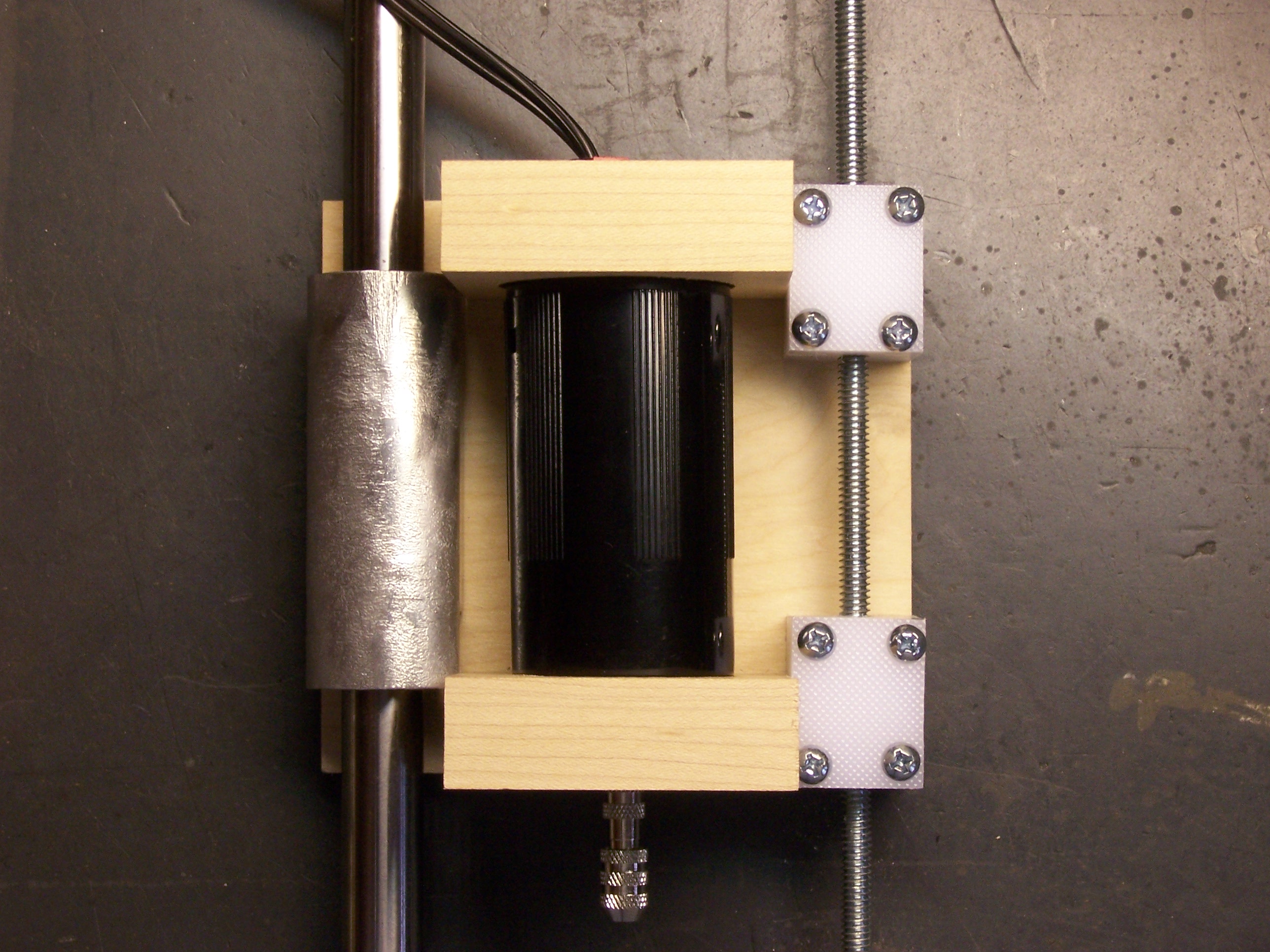
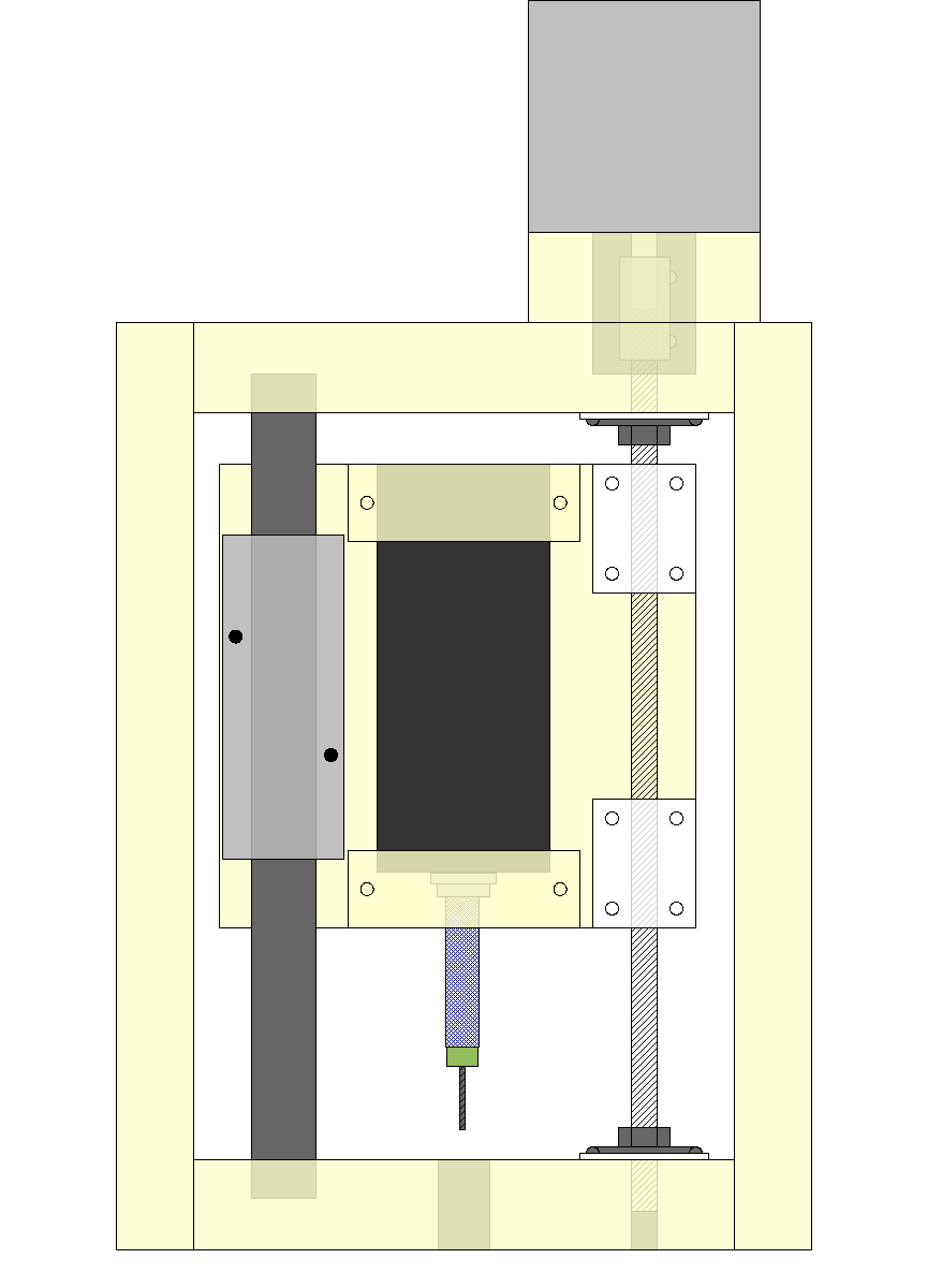
I got the sled (or platform) built that will move the drill up and down (Z axis) in my CNC machine. I spent over a week trying to figure out how to make thrust (axial load) bearings for the lead screw, so that all of the motor’s rotary motion is translated into vertical movement of the drill, not vertical movement of the screw itself. I’m still not completely sure that my plan for that will work, but at least I have something to try in the next stage I’m going to build.

I need to find and learn to use an open-source 3D CAD program; but meanwhile, I laid this out in OpenOffice Draw. I had started by tracing the different pieces onto graph paper by hand; but the design didn’t really pick up steam until I got them into the computer, where I could drag and resize components easily. Several times when I thought I was done, I saw the opportunity to shrink things a little closer together — which ultimately translates into the capacity to work a larger piece, as less of the length of the guide rods is consumed by the width of the sled.

CNC drill sled design, front view

Here’s my final design — final for the prototype machine, anyway. And here’s what it looks like in the physical world — a pretty close match.

CNC drill sled, front view

The drill is held by two square blocks with round holes drilled out in their centers. I goofed and cut the blocks to 2 1/4″ instead of 2 1/8″, so the whole platform now fits together a little tightly, and the alignment of the guide rod on the left is a little off; I’ll have to compensate for that later on. And the drill fits a little loosely in the holes because they’re a bit too large, but I’ll add some thin weatherstripping to grip the drill tightly.

The white blocks on the right are built up from two layers of polypropylene kitchen cutting board, superglued together, with a hole tapped through lengthwise for the threaded rod (1/4″ all-thread). When the rod turns, it will push the drill down or pull it back up.

On the left are a bearing glide and stainless steel rod salvaged from a workhorse IBM dot-matrix printer. A computer surplus store in Wichita had a closing sale a few years back, and when no one bought the printers, the owner suggested that I haul them off. I dutifully removed all the electronics, boxed up the mechanical components, and deposited the plastic for recycling. At last the mechanics are finding a new use. :-)

This assembly will be oriented with the drill pointing down, and a frame will surround it in the Y-Z (vertical) plane. The frame is shown in the drawing but not in the photograph; it’s the next piece to be constructed. The frame will anchor both ends of the guide rod and the lead screw, provide a mount for the motor, and mount two glide assemblies to move the entire frame sideways in the Y (short horizontal) axis.

Motor Mounting

The motor isn’t mounted to the screw right now, since it mounts from the outside of the (yet-to-be-constructed) frame. But I’ve been looking for a good coupler to join the motor shaft to the threaded rod. The ideal coupler would help compensate for slight misalignment between the axes of the motor and the rod, but really good couplers seem to cost $60-$80.

I’ve found one at Jameco that’s much more affordable (just under $5) and looks like it’ll do the job nicely. It has a rubber “spider” enclosed between two pronged pieces. The spider has a little bit of “give” to it, to correct for misalignment. It should also help damp transmission of noise and vibration between the motor and the screw.

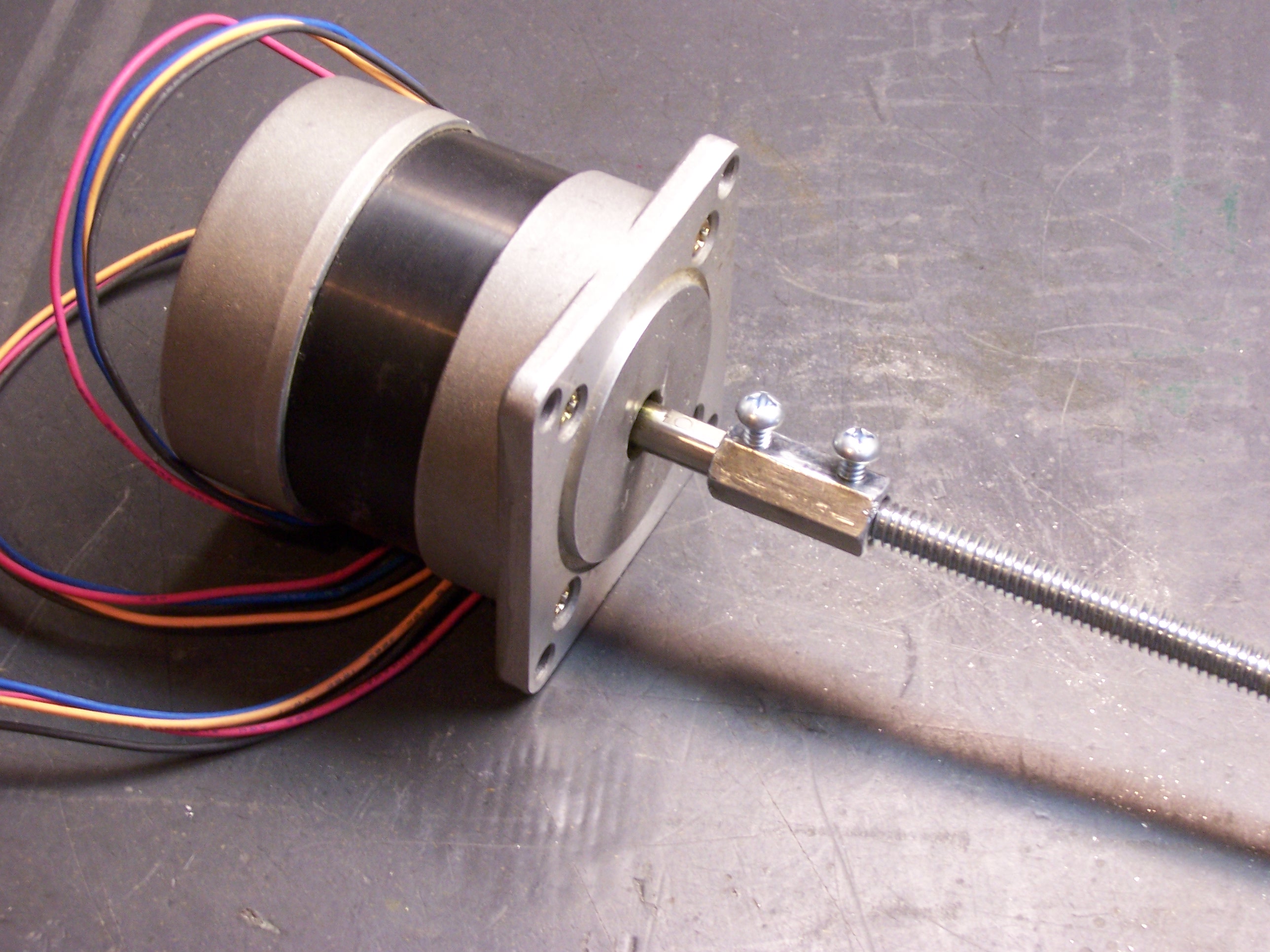
Stepper motor with homemade shaft coupler, angled view

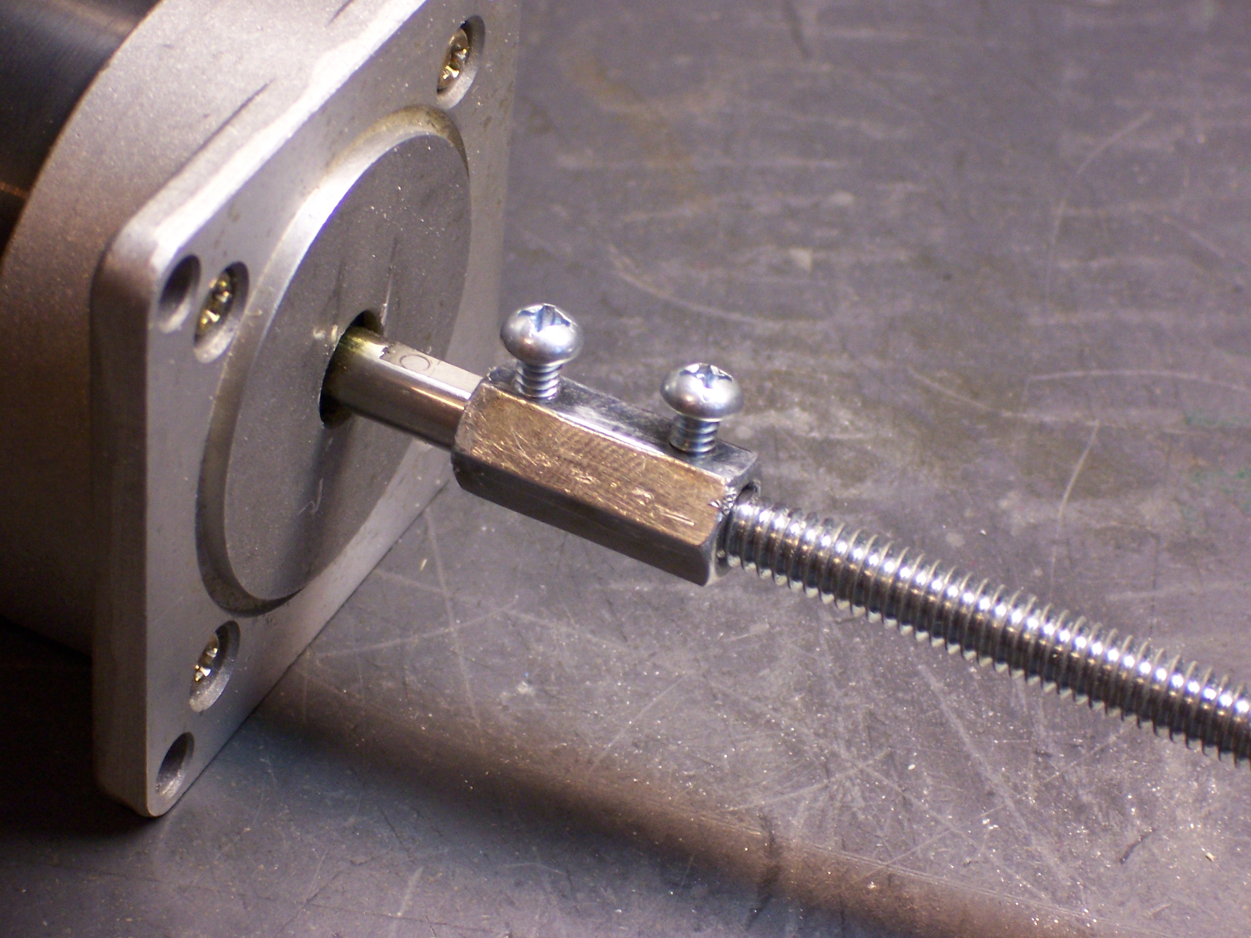
Meanwhile, I’ve built a cheapo prototype coupler myself. I got a $1.49 threaded coupler from Ace Hardware, drilled out half of it to 1/4″, and drilled and tapped holes for set screws. I pressed the drilled end onto the motor’s shaft, filed a flat into the threaded rod and turned it in to the threaded end, and tightened the two set screws. I need to file off some of the set screws’ length, but it’s working okay for a proof of concept.

Homemade shaft coupler

Fire Alarm Dialer

April 28th, 2007 by Keith Neufeld

What shall I do with this?

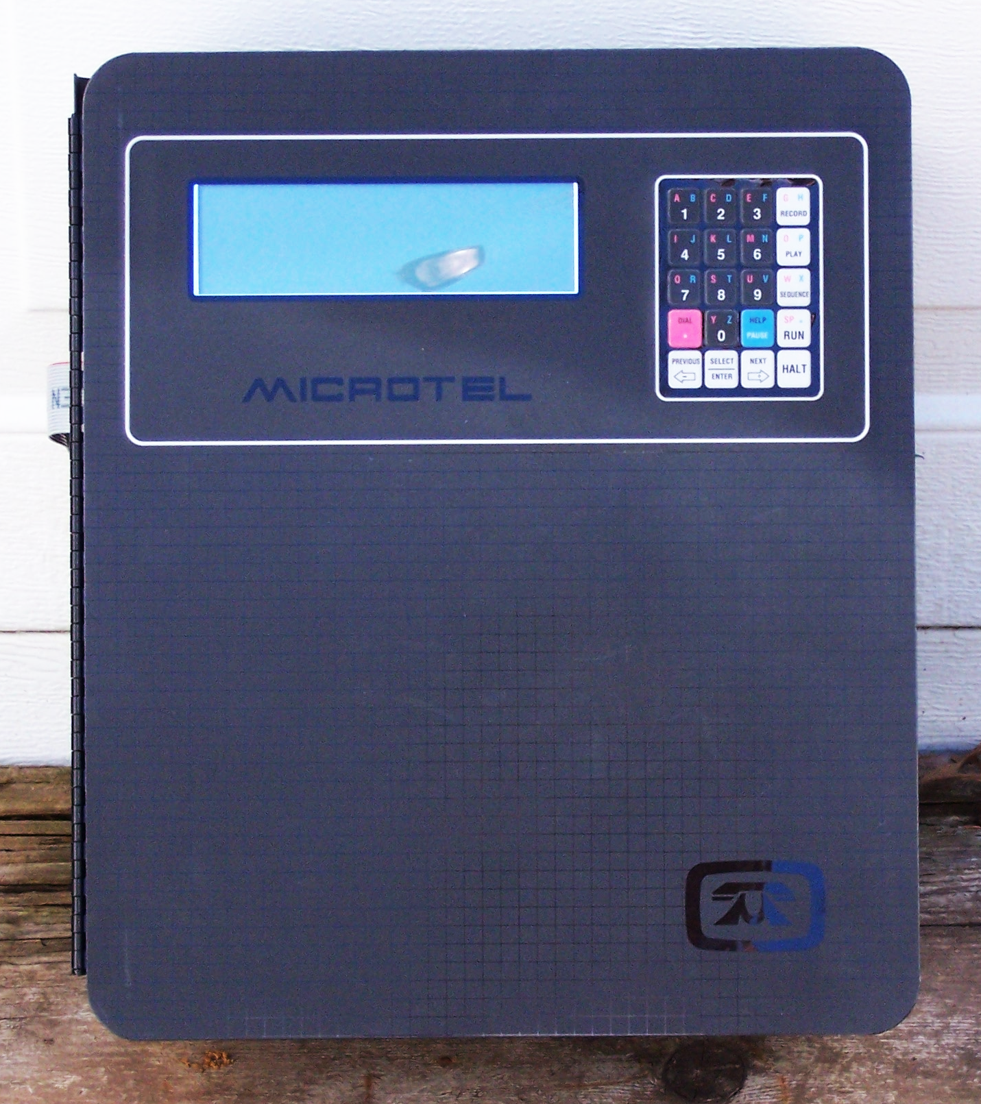
Fire alarm dialer box, front

You know your reputation as a salvager is increasing when the campus fire chief walks into your office and says, “I hear you might be interested in this.”

Yes. Yes I am.

Fire alarm dialer box, open

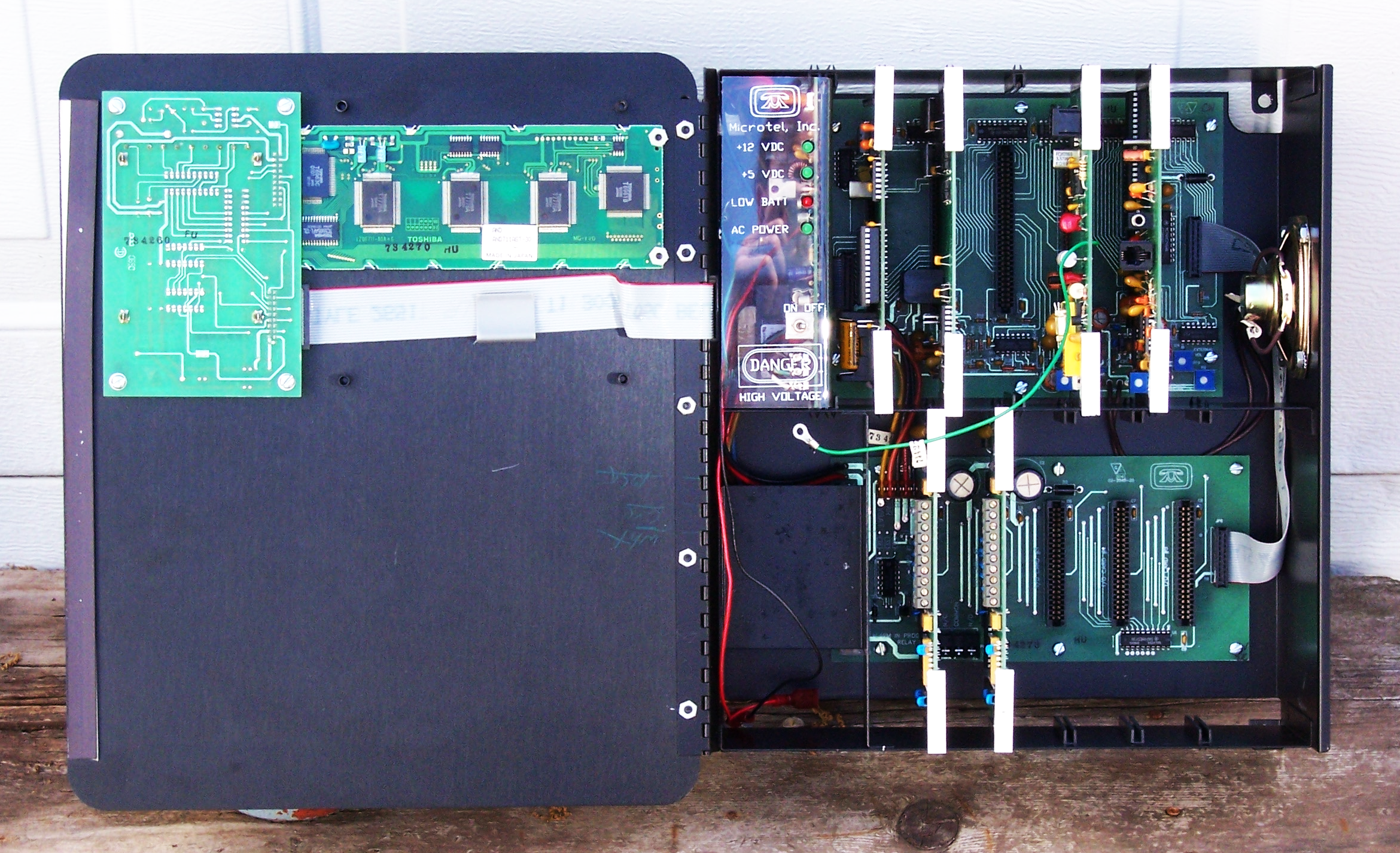
It’s a Microtel automatic dialer, built to watch a variety of analog and digital inputs, dial telephone numbers in response to alarm conditions, and play recorded and/or synthesized messages. It was installed under the floor of our data center, and apparently at some point its power was disconnected. After the backup gel battery drained, the voice card lost its mind. It’s old enough that they decided to replace the whole unit rather than the voice card.

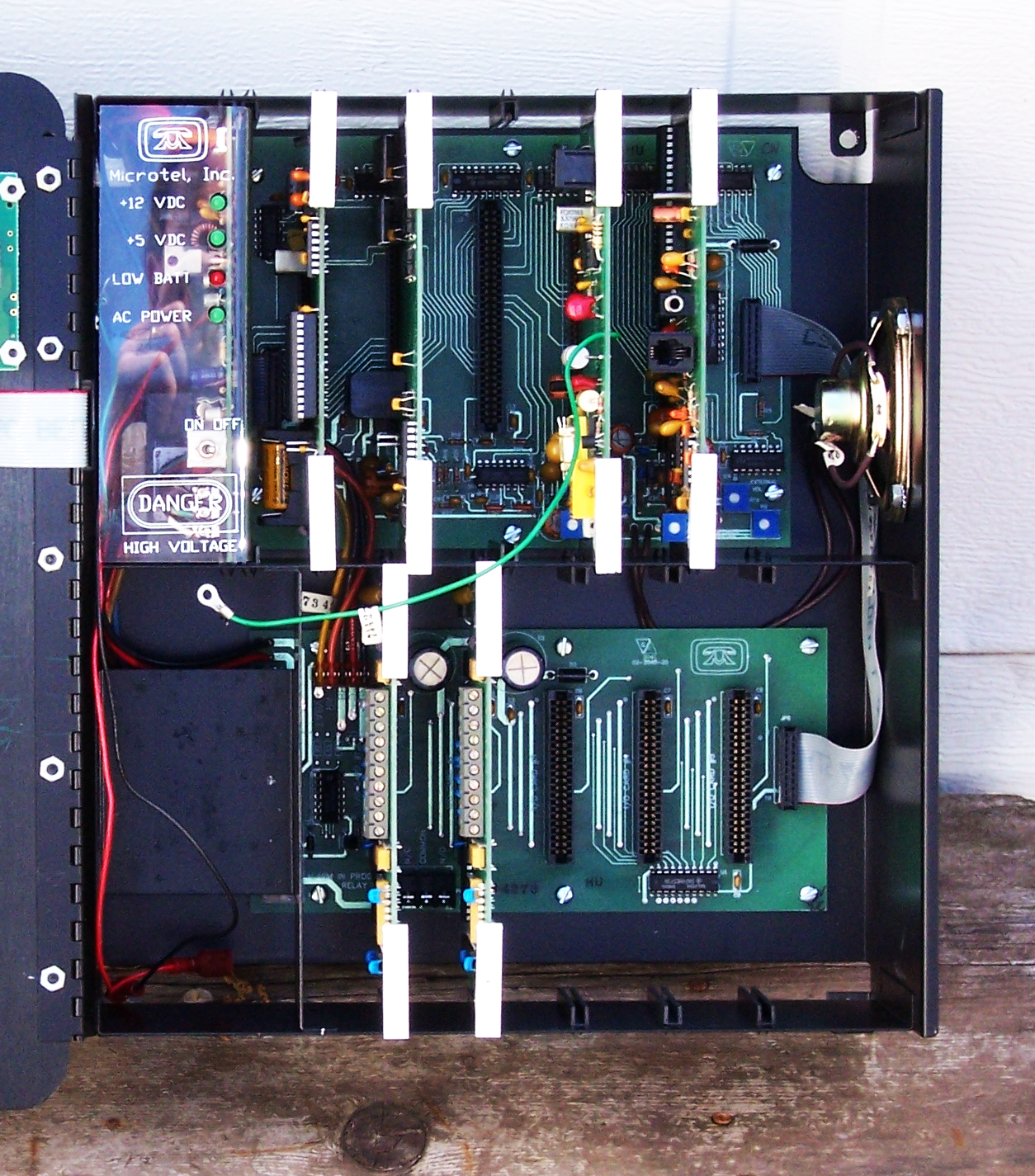
Fire alarm dialer box, interior

The upper row is the system bus, containing the power supply, the CPU card, a voice memory card, and a telephone interface card. I’m not sure yet what the other card is. The lower row is the I/O bus, with two digital input cards.

What to Do?

I think it’s pretty cool. It’s a really nice enclosure. I love the LCD on the front panel, which looks like it has a parallel interface that should be easy to hack. The cards are intriguing, particularly if one of the chips is a voice synthesizer. The power supply offers 5V and 12V, and already knows how to charge a gel cell and cut over to it when power fails.

But I’m surprised at the enthusiastic response I’m getting from non-electronics-geeks. The normally reserved Garrett positively gushed over it, and today my friend Jonathan (ER nurse and fix-it guy) expressed how awesome it was, and how many cool things you could do with it.

All right, then, you tell me. What should I do with it? Enclosure, components, or the works?

Stepper Motor Controller Board

April 22nd, 2007 by Keith Neufeld

Keeping a blog is a great way to realize exactly how long some of my projects sit on the shelf–until recently, I haven’t worked on my CNC milling machine project since last May. Hoo boy.

Last time I discussed it, I’d been experimenting with the stepper motors I want to use to drive it, and the last thing I had done was build a driver out of discrete, complementary MOSFETs. I was hitting about 500 steps (2.5 revolutions) per second, and the output transistors were getting pretty warm. Plus I was using a 12V supply to feed the motor’s coils that only want about 2.1V each, so I was throwing away the rest of the voltage in huge sand resistors.

Allegro A3977 Stepper Driver

I was interested in trying a dedicated stepper controller chip, and I found the A3977 microstepping driver chip from Allegro Microsystems. It’s rated for 2.5A per coil (the same as my motors) and looked perfect for my application, so I ordered a few samples.

The A3977, like many other current-controlled drivers, has each load (motor coil) in series with a sense resistor, to measure the current actually flowing through the coil. The A3977 ramps up the load voltage until the sense voltage reaches a (designer-controlled) threshold, then shuts it off and ramps again. Thus the average current through the coil (when energized) can be controlled by the combination of sense resistor value and reference threshold voltage.

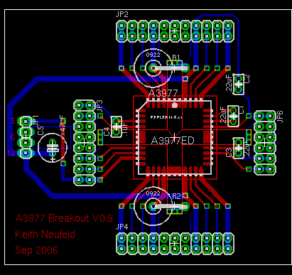
Clear back in September (ahem), I laid out a breakout board for the A3977, to make sure I understood how to control it before building real control boards for the CNC machine. I put on header sockets to make it easy to try different parts values; about the only parts soldered onto the board are the A3977 itself and several required capacitors whose values are specified on the datasheet.

I also planned to solder the sense resistors; their resistance is so low that an oxidized socket could add resistance equal to a significant fraction of the resistors themselves.

A3977 breakout board

The biggest challenge in the layout was designing adequate heatsinking. The A3977 doesn’t have a solder pad on its belly, and I’d have had a hard time soldering it even if it did. Instead, the three pins at the center of each edge are ground pins that double as heatsinks, and they want a big copper area for dissipating heat.

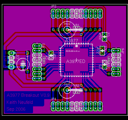
I used EAGLE’s polygon feature (I think that’s what it was called; I should have taken better notes while I was doing this) to make big copper areas. In the above picture, the brighter red and blue outlines show areas that will be filled with copper on their respective sides of the board.

A3977 breakout board with polygons filled

Hitting the ratsnest button then flood-fills copper into not only those areas, but the rest of the board, leaving a specified gap between the copper ground plane and any pins not specifically identified for inclusion. Since I was planning to etch the board in the sink, leaving large copper areas not only provides the requisite heatsinking, but saves on etchant and etching time.

Building the Board

Immediately after making the board, I got the A3977 soldered onto it. Because the board was hand-etched, it was a lot dirtier than professionally-manufactured boards, and soldering the big PLCC chip onto it was correspondingly more difficult. But I got all good joints and no bridges, as confirmed with the continuity tester.

And then the board sat from September through April. Sigh.

A Kick in the Seat

A few weeks ago, I suggested to John Harrison that we needed to get back into having a “geek club” meeting every Monday night this summer–and that at every meeting, every member had to show or demo significant progress on some project. It’s amazing how much you can get done when you have peer expectations of continuous achievement.

I called John on Friday evening and told him that I needed a pep talk: I had a wide open weekend and two electronics projects that I could work on but was reluctant (and/or intimidated) to start. I could finish the work and blog on repurposing a battery-operated motion sensor (coming soon) for class, or work on my stepper controller.

He asked which one I was going to show him on Monday night. Well!

That was the motivation I needed, even though it turned out he’s out of town Monday. By the time I went to bed Friday night, I had the whole board assembled (except for the pieces I forgot). Instead the motor running, though, it kind of twitched and buzzed.

I reread the datasheets and applications notes as I was going to bed, and realized I had somehow left out the RC components for the output waveform generators. My wife woke me up at 6:30 Saturday morning for help with the laser printer before running off to manage the local food coop’s distribution day, and by the time normal people were up, I had the controller running the motor at full speed.

Stepper motor controller board

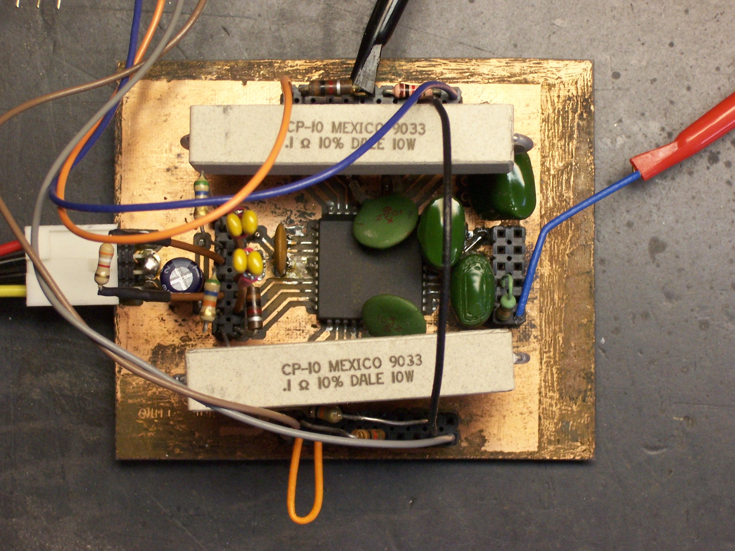
Here’s what the board looks like with everything installed. The big sand resistors are the sense resistors–and yes, that is .1Ω (although I tried .2Ω first and will probably go back to it). The weird green things are capacitors for an internal voltage boost circuit. The motor coils are fed from the orange, blue, brown, and grey wires that take off from the upper and lower corners. Power from a PC power supply comes in the left, and the red probe and blue wire on the right provide a step signal from my function generator so I can test without hooking up a microcontroller. The extra wires and resistors around the outside are jumpering things like /RESET, /ENABLE, and DIR, again to facilitate μcontless testing.

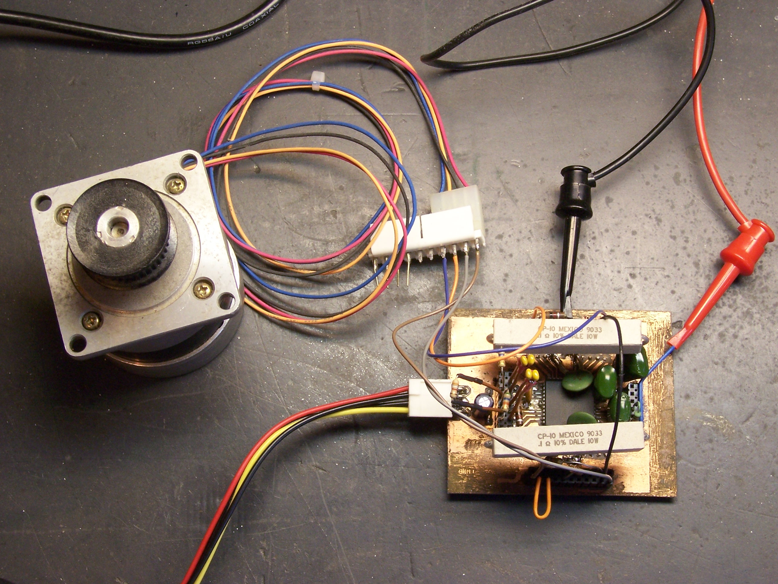
Stepper motor controller

Thar’s what it looks like with the motor.

How It Works and Lessons Learned

Speed

I was surprised that I wasn’t able to get it to run faster than it does. I haven’t measured exactly, but I guesstimated I was hitting about 600 steps per second (3 revolutions per second) before it started jittering instead of turning. I tried half- and quarter-stepping (at correspondingly higher clock rates), hoping the smoother drive would increase the maximum rotation speed, but it didn’t. I swapped out the sense resistors to increase the motor current, but that didn’t increase the maximum speed either. I could tinker with the ramp generator’s RC values, but I don’t think that’ll help either. The controller is rated for 600,000 steps per second (!!!), so I’m pretty sure the limitation here is the motor, and I’m just pushing it as fast as it can go.

That’s a little disappointing, because (1) that’s only a little faster than the 500 steps/second I was getting with my MOSFET driver; and more to the point, (2) with a 20 thread per inch lead screw, 3 revolutions per second works out to about seven seconds per inch of travel. That is, if the cutter head is at the opposite side of a sheet of typing paper and needs to come back, it’ll take a minute for it to travel across. That’s pretty painful.

The documentation at the LinuxCNC (née EMC) web site suggests that high-speed CNC machines use DC motors with optical encoders, rather than steppers. I guess I’ll look into that for version n + 1.

Advantages?

I’d been hoping that the current-control system would be the silver bullet that pumped this motor up to dramatically higher speeds. Since that’s clearly not the case, is it still worth using this chip over the discrete MOSFET design I made?

I say yes. The A3977 is much smaller than the eight TO-220 FETs (plus heatsinks) required in the discrete transistor design.

The A3977 also runs a lot cooler. Its temperature rose to the mid 90°F range after several minutes of continuous full-speed operation. In contrast, the FETs got hot enough to burn fingers (I didn’t have my infrared thermometer yet) after only a few seconds of operation.

Allegro would claim that the A3977 also improves the pin count for processor interfacing–it requires only two pins (direction and step), whereas the discrete transistor solution requires four pins (two wires each for two coils). This is probably valid, although the plethora of options (half-, quad-, and eighth- stepping, reset, etc.) will tempt me to use up those saved pins controlling other facets of the stepper operation.

Sense Resistors

I had ordered big sand resistors with thoughts of stacking them to kill voltage in my MOSFET design. But defining ITRIPMAX as the maximum instantaneous current of each output ramp cycle (in my case somewhere between 2.5A and 5A), the A3977 recommends:

VREF = 4V
RSENSE = VREF / (8 * ITRIPMAX)
      = 4V / (8 * 2.5) = .2Ω

Which is what I’m using. BUT working back:

V = I * R
VR = 2.5A * .2Ω = .5V

P = V * I
P = .5V * 2.5A = 1.25W

So the resistors need to be large, but not quite so monstrously huge. (These are 10W.) I’ll shop for smaller ones before building the real board.

PC Board Vise

April 22nd, 2007 by Keith Neufeld

I’d heard that PC board vises were the cat’s meow for stuffing and soldering boards, and I’ve seen them used in a couple of “how to solder” videos. So when my friend Cort was putting together a big parts order recently, I had him add on a vise for me. Here it is.

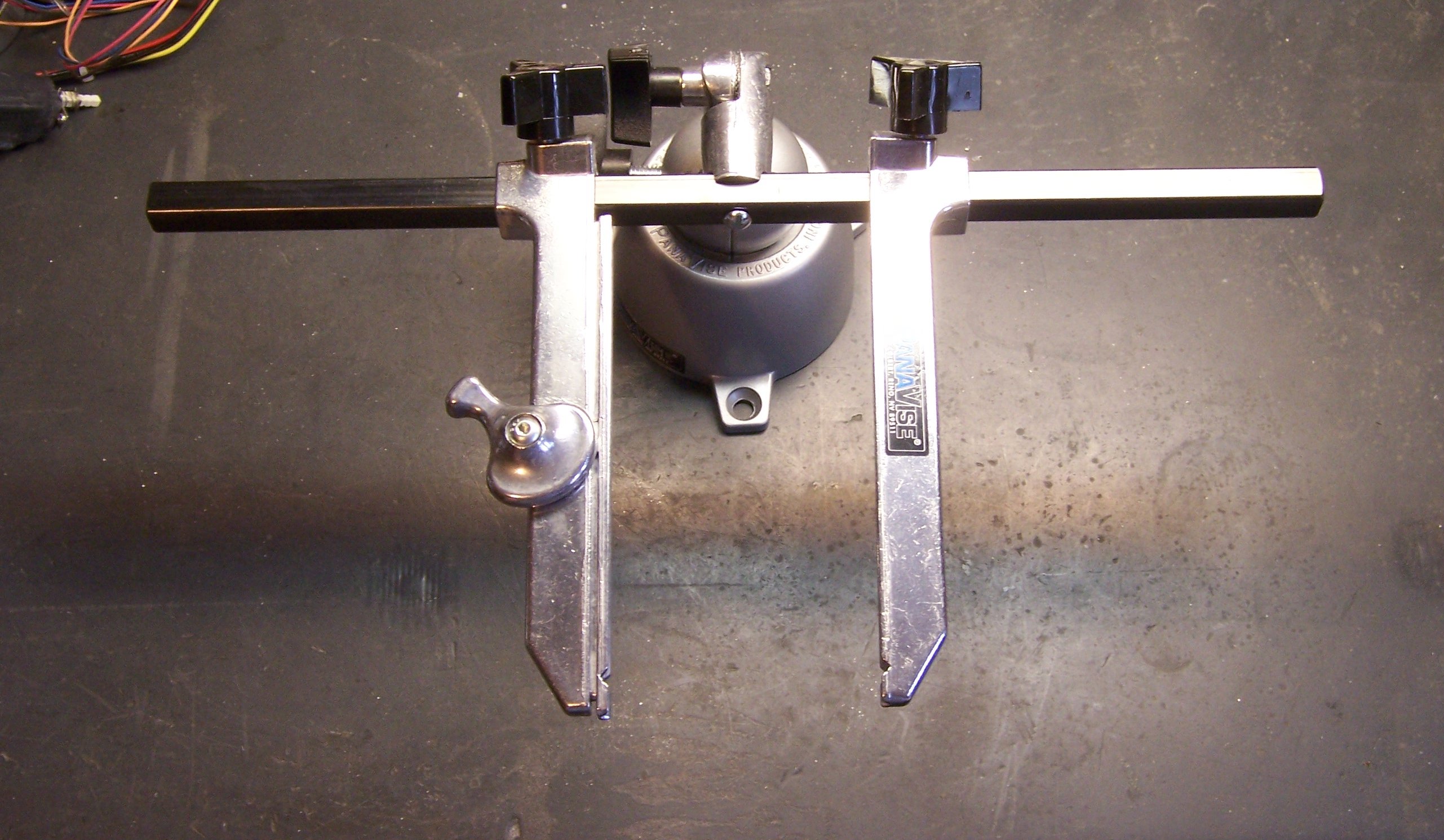
PCB vise

It came in pieces: the base, the spindle, the bar, the clamps, and all the knobs. Pretty easy to put together, but I had one little problem:

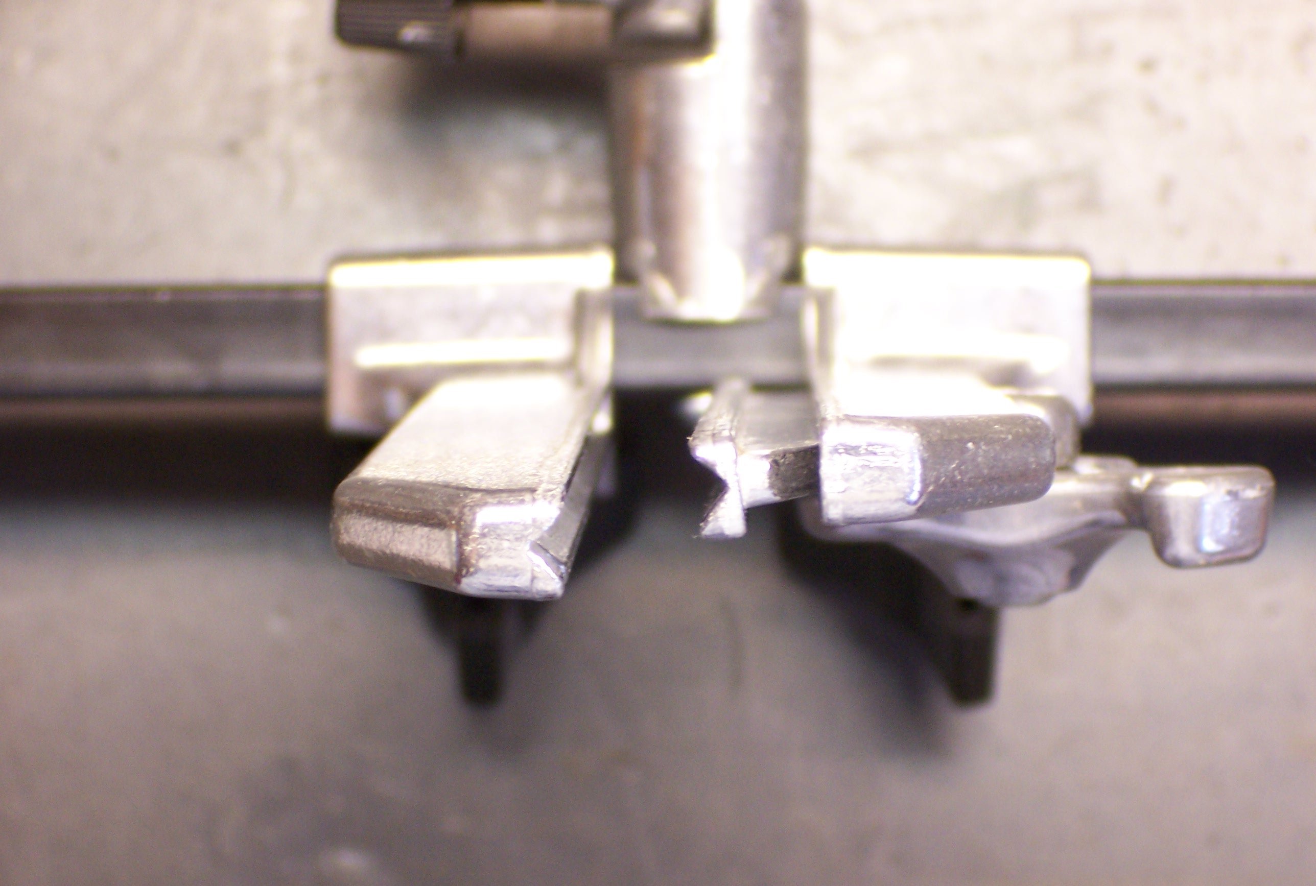
PCB vise with misaligned jaws

The jaws didn’t line up. Like, so bad there’s no way I could make a decent PCB stay put.

The square holes to fit over the bar had casting flash left in them; and the bar itself is rhomboid instead of square, so it doesn’t fit snugly into the jaws’ (allegedly-)square corners. It was even possible to wiggle the jaws and make them misalign in the other direction, but not to get them to stay aligned.

PCB vise with realigned jaws

So earlier this weekend, I sat down with a square file and got all the flash out. I also found which way the clamps fit best on the bar and reoriented them to that position. Now they’re stable and pretty well aligned.

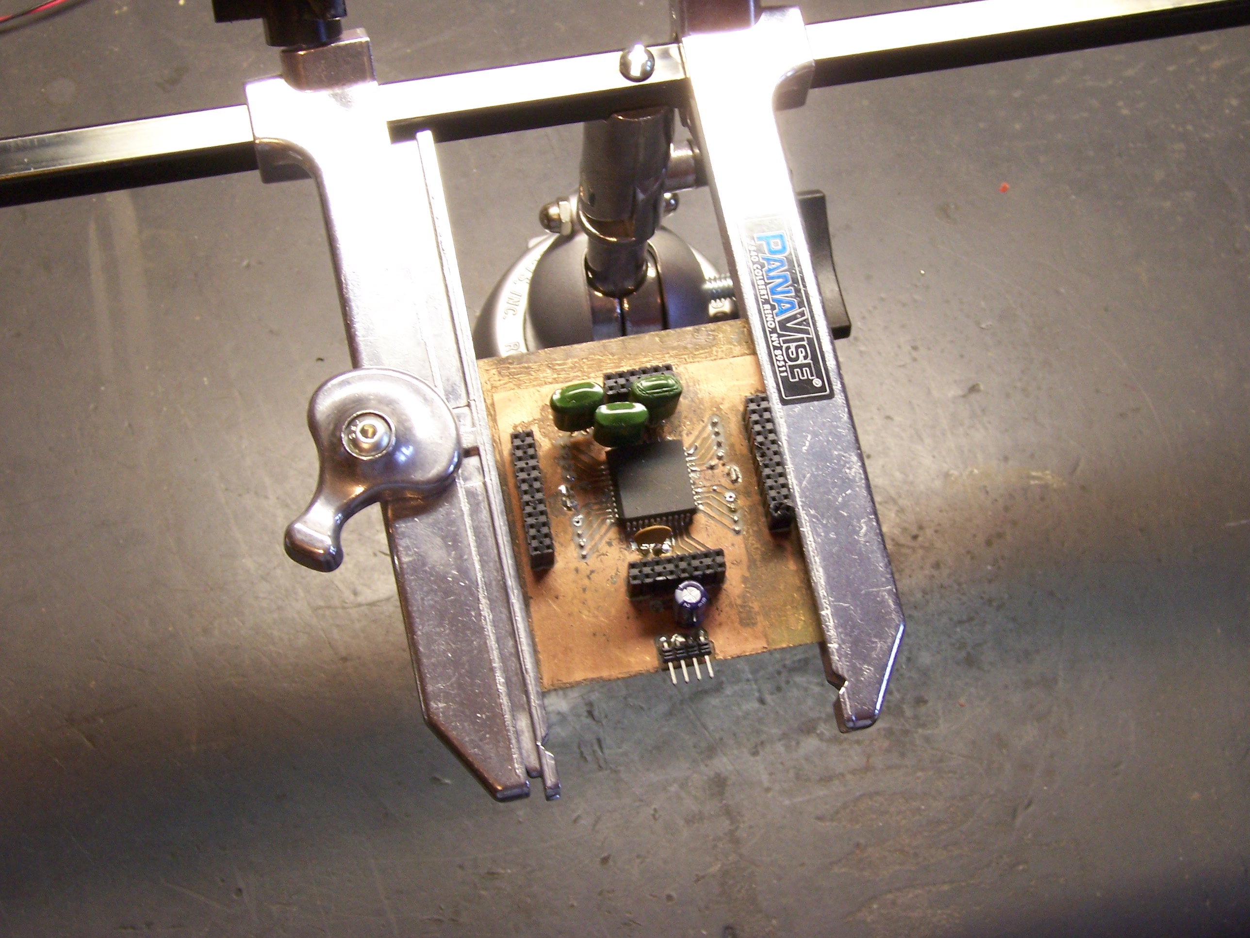
PCB vise holding my stepper control board

I got to use it for soldering some of the last components of my stepper control board. The vise’s spindle has a joint that folds 90° forward or back, so I assembled it to have the jaws pointing straight up when the spindle is straight. I fold it forward to do top-side work, and then fold it back up and over backward to do bottom-side working. Verra nice!

Nightmare Workbench

April 22nd, 2007 by Keith Neufeld

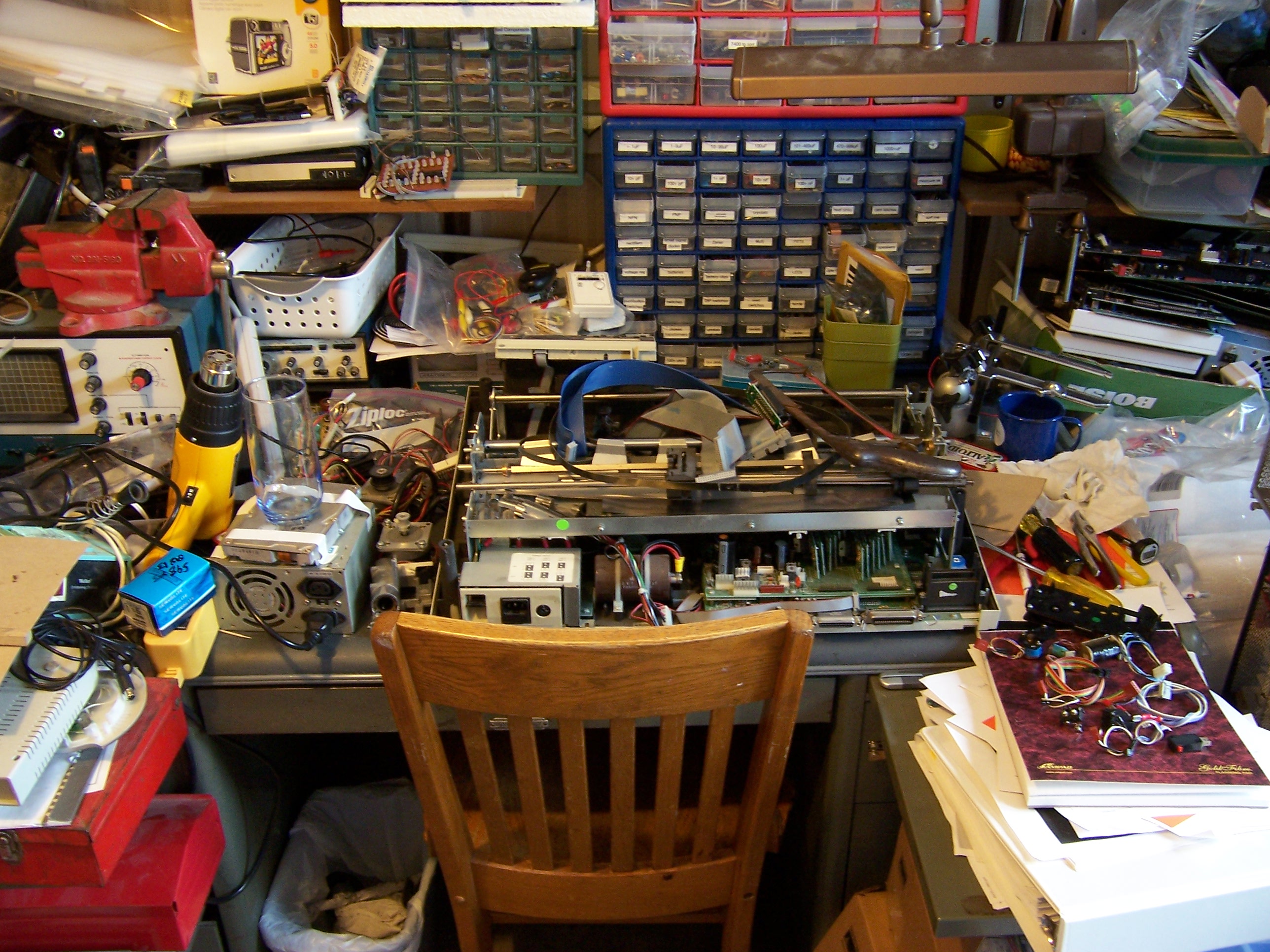
My workbench

I think it might be time for me to tidy a bit.

Rice Krispies Five-Digit Counter

April 19th, 2007 by Keith Neufeld

Look what my wife found in a Rice Krispies box!

Mickey Mouse step counter from Rice Krispies box

It’s a five-digit counter module! Oh, it’s supposed to count your steps while you walk around at Disneyland, but why shouldn’t it be able to count other things???

Okay, let’s do it.

Digging In

Here’s the back side of the case.

Counter case, back side

OH NOES!!! Triangle-drive screws! Whatever shall we do???

Security bit set

:-)

Counter, interior view from above

Here’s the inside. The metal arm at the upper left has a small weight, nearly balanced by the hairspring. It bobs up and down when you walk, making contact on the downstrokes with the metal tab at the corner of the PC board.

Counter, interior view

The Guts

After removal of the two screws holding down the weight, the active electronics pop out–still running.

Counter module, extracted

Disassembling the screws from the back of the PCB enables it to be separated from the screen.

Counter PCB and screen assembly

Note the anisotropic strip on the LCD. It looks like a strip of rubber, but conducts electricity only in the direction of its width (which is oriented vertically here). It interconnects the display contacts on the PCB with the contacts on the LCD, just by virtue of being squeezed between them.

Counter module, back side of screen

Mickey, Meet Jack

It’d be nice to be able to continue using this as a pedometer, but connect something else to count. And it’d be nice if connecting something else disabled the internal counter so you didn’t get extra counts from bouncy bouncy, right?

So we need a closed-circuit jack. It feeds a default signal to the destination, and disconnects the default when you plug something in. Think of plugging headphones into a receiver and it shutting off the speakers . . . or plugging a headset into a cell phone and it disabling the built-in earpiece and mike.

Main board from Motorola cell phone

[A few frustrating minutes with a good soldering iron and a bad piece of solder wick later . . .]

Closed-circuit jack from Motorola cell phone

The jack. Or in French, Le Jacques.

According to my continuity meter, the connections closest to each other on each side are normally closed (NC), and open to break the connection when a plug is inserted. The ones nearest the plug end make connection with the plug, and the ones furthest from the plug end get disconnected.

This jack is made for a stereo plug (common plus two wires), but we only need mono (common plus one wire). Which of the contacts touches the tip, and which the sleeve? I don’t know! We’ll connect both!

Counter case with jack fitted in place

Hold. Mark. Drill tiny. Enlarge. Enlarge. Enlarge. Step-drill. Step-enlarge. Step-enlarge. Voila! Or in French, voila!

Counter case with jack fitted in place, end view

Mickey, Meet Wire

Hum tiddle-um, time to do some wiring. Need to break the connection on one side of the weight-switch and reroute it through the default (NC) pins on the jack. The big metal strip that the weight hits is pretty directly connected to what turns out to be the + power lead, so it’s easier to interject into the hairspring’s connection (the big solder blob in the lower middle).

Counter PCB with trace cut and cleaned

Scrape, scrape, scrape, scrape, scrape. Clean the green varnish off the trace. Then cut the trace (just above the mounting hole).

Counter PCB with fly wires attached

And solder on some fly wires to go to the jack. I knew that my leftover wire wrap would come in handy someday. One piece to each side of the cut trace, and one piece to the + power supply (to take the place of the weight switch).

Counter module, rewired

After some notching of the LCD case (more than was intended, thanks to lack of planning), the module can be closed back up. I highly recommend putting the battery connector in the wrong place, so there can be more takey-aparty and putty-back-togethery. Then wire to the jack, connecting to both sides as mentioned earlier. (See the bare wires running across the left end?)

Or in French, Voilalala!

Counter, reassembled with new jack

One completed, rewired, general-purpose, five-digit decimal counter.