Blue LED Clock

May 27th, 2006 by Keith Neufeld

CK-3000

A few days ago, I ran across this custom PC case via the Make blog:

WMD PC Case Mod

G-Gnome’s “WMD” Case Mod

Via
Build process, part I
Build process, part II

It’s an amazing piece of work–all hand-tooled metal, with lots and lots of polishing.

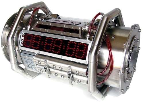
One thing that caught my attention was the clock display. It looked cool, I loved the way it used individual round LEDs as pixels instead of big segments and made the digits look rounder, and I wanted one. I read through the story. I found that the clock is the CK-3000 from Electronics USA. It’s $360.

That’s just crazy.

Design

Then two thing happened at about the same time. I emailed my friend Jeremy the links to the WMD PC case, and I started thinking about building my own clock as a backlash against the price tag on the CK-3000. Then I was talking to Jeremy about building an eye-searing blue LED model; and the next thing you know, we’re starting to discuss actual details.

Jeremy writes:

I’m mostly after a scary looking display (I realize red would be scarier, but I like blue). Being big(ger than a sane person would want a display) is part of that because something that big MUST be important, but it has to be a manageable size. 3 or 4 feet would probably be the limits for me to find a permanent spot to hang it in the computer room and smaller is not necessarily worse if we can get the feel of the thing right. Being ominous on its own is good, but it should definitely DO something. A regular clock would be bare minimum, a clock that freaks out and does a flashing doomsday 1 minute countdown every hour (or randomly… that would be scarier) would be the kind of thing I’m going for.

And I replied:

Can we make it do that in _response_ to something? Lights turned on or off, loud noise, silence? We can definitely add a horn/buzzer/piercing alarm to sound continuously/beep down the seconds/beep frantically for the last few seconds.

Um, if it’s going to be ominous, it should have a hundredths display, so some of the digits are changing too rapidly to see. The hundredths might remain blank during normal operation and only kick in when we’re down to a minute left, or something.

Technology

I think I may actually build one or two of these. I’d use the LogoChip for timekeeping and display decoding, probably supplemented by watching the 60Hz on the power line. I got a string of 5mm blue LED Christmas lights last winter, and I might get more, or I might get some frosted blue LEDs on eBay.

To drive the display, I’m interested in using Allegro Microdevices’ A6275 and/or A6276, 8- and 16-bit constant-current LED drivers. I saw them used in something linked from the Make blog that I can’t remember now, I ordered a couple of 8-bit sample chips to play with, and I recommended them to Muaz Halim for use in the TechArt exhibit Firefly Environment.

Roomba Repair

May 21st, 2006 by Keith Neufeld

I fixed my original Roomba this weekend, repairing a blown trace due to incorrect battery rebuild instructions, and learning other interesting things along the way.

Repairing Roomba Original

Stepper Motors, Part V: Taming the Wild Voltage

May 20th, 2006 by Keith Neufeld

With a desired motor voltage of ~2V and the bridge feeding the coils ~11V, the motor draws way more current than it needs, and the FETs get really hot. In fact, the PC power supply I’m using, which is rated for 7.5A of 12V, can’t keep up with the load. It makes sense:

11.4V / .85Ω ≅ 13.4A

And that’s per coil, so almost 27A draw for the two-coil motor. When I measured the voltage drop across one coil, it was actually only a little over 3V. I had known I was going to want to drop the bridge voltage so the motor coils didn’t get the full 11.4V, and I had thought about doing it with diodes or resistors. Before going any further (laying out a PCB), it was obvously time to deal with the overvoltage; so last night, I sat down to do some calculations.

Dropping Voltage with Diodes

I don’t know why, but my first inclination was to try to drop the voltage with a string of diodes. Given

bridge voltage: 11.4V
desired motor voltage: ~2V

then

required drop: ~9.4V

With a .6V drop for small-signal diodes:

drop per diode: .6V
diodes required: 9.4V / (.6V / diode) ≅ 15.7 diodes

And assuming I was willing to string together 15 diodes in each direction, for each coil of each motor (uh, 15 * 2 * 2 * 3 = 180 diodes in the milling machine just for dropping voltage), how close would that get?

drop for 15 diodes: 15 diodes (.6V / diode) = 9V
motor voltage with 15 diodes: 11.4V – 9V = 2.4V
current with 15 diodes: 2.4V / .85Ω ≅ 2.8A

Granted, the rectifiers I’d actually use have a voltage drop more like 1V to 1.25V per diode; but that’s still 9 * 2 * 2 * 3 = 108 diodes in the project. Way too wasteful, and way too many.

Dropping Voltage with Resistors

It seems that Tom McGuire’s suggestion to use power resistors is the right way to go. Big sand resistors can dissipate a lot of power, but how much would be required? From above,

required drop: ~9.4V

And given

coil current: 2.5A

then each resistor would need to be capable of

9.4V * 2.5A ≅ 23.5W

That’s a pretty hefty resistor!

I looked through my parts bin, but most of my power resistors have a much higher resistance. I also browsed power resistors at All Electronics and found a few ceramics rated for 25W–but I didn’t want to have to come up with enough stuff to place a minimum (reasonable) order, wait for it to arrive, and then take a chance of it not meeting my needs. As it turns out, Radio Shack carries an 8Ω 20W resistor, so today I trotted on down and picked up a couple.

I hooked one in series with each motor coil and ran through my barrage of tests. After reconnecting a loose signal wire from the controller (oopsie!), I found that the motor was much easier to stop by gripping it with my fingertips, it had a much lower top speed without losing steps, and the coil voltage was only a little over 1V.

Dropping Voltage with the Right Resistors

At no point in the resistor discussion do I describe figuring out exactly what resistance is appropriate, because I was too impatient to get on with prototyping to be bothered with calculating. Sigh.

Okay, so I want ~9.3V dropped across the resistor and ~2.1V dropped across the motor; and the motor coil is ~.85Ω.

9.3V / 2.1V = R / .85Ω
R = .85Ω (9.3V / 2.1V) ≅ 3.8Ω

So I was embarassingly far off with my 8Ω resistors, which explains the low voltage and poor performance when I tested them.

Hmmm . . . 3.8Ω is really close to half of 8Ω. Now I’m tempted to go back and buy two more of the 8Ω resistors, to test in parallel.

On the other hand, it’d be nice to try a range of values centered around 3.8Ω, to graph the motor performance and find whether the curve has a knee in that vicinity. So now I’m back to looking at All Electronics, thinking of ordering myself an assortment. They don’t have anything in the 4Ω range, but they have 1.2Ω, 1.3Ω, 1.5Ω, and 2Ω in power ratings I could work with.

Stepper Motors, Part IV: Speed Trials

May 14th, 2006 by Keith Neufeld

First Real Motion

Tuesday night, I duplicated my H-bridge circuit for the second coil of my stepper. I provided drive power from my bench power supply, because I wanted to be able to vary it to test the effects of different supply voltages. And I didn’t (yet) do anything to drop the bridge’s voltage down to the ~2.5V that the motor wants–I just let the motor have whatever came through the bridge. The motor is hefty enough, I didn’t figure it would be damaged during brief tests.

Dual H-Bridge MOSFET Stepper Motor Driver

I hooked up the motor, started my LogoChip program with a clockwise drive pattern, and slowly turned up the supply voltage. Around 2-3V, the motor started chunking along. And I found that I couldn’t supply more than 2-3V–no matter how high I turned my variable supply (like, up to 20V), it wouldn’t provide more than 2-3V. It’s only rated for 1.5A on the channel I was using, and it was giving everything it had.

Using a loop [ step-cw mwait ___ ] command from the LogoChip console, I was able to get down to 4ms wait without losing steps, or 250 steps per second. I assumed that with a stronger power supply, I could do at least a little better than that, and I was not to be disappointed.

Dedicated Power Supply

Wednesday night, I brought in an old PC power supply and wired it into the driver board. I first used its 5V supply to power the driver, wanting to work up to 12V in stages. It was clearly driving the motor more powerfully than my bench supply did Tuesday night–motion was smoother and able to run at slightly higher speeds.

Next, I switched it over to using the 12V supply. Ideally, I’d like to run it on 8-9V, but I wanted to see what 12V did to the FETs and motor. As expected, running on 12V gave the best performance I’ve experienced yet. I was unable to stop the motor’s movement by gripping the 1″-diameter pulley with my fingertips (!), and I was able to get down to a 2ms wait in the loop shown above without losing steps.

How Fast Is That?

It was losing steps continually with a 1ms wait, but that’s a full factor of two difference in speed from the 2ms wait, so I was curious where between the two the fastest possible speed lay. I rewrote the loop to use a no-op (which the LogoChip Language Reference lists as 13μs) for the delay instead, and tweaked it down to about 150 no-ops without losing steps. Since 150 * 13μs = 1950μs ≅ 2ms, it looks like that’s about as fast as I’ll be able to get the motor to run with the current drive system.

What does that translate to in the real world? 2ms / step = 500 steps / second. This stepper has 200 steps per revolution, so 500 steps / second = 2.5 revolutions / second. I was planning to use 20 tpi all-thread for the drive screws, so (2.5 revolutions / second) / (20 revolutions / inch) = 1/8″ / second. That’s kinda slow.

Speed Improvements?

I deliberately designed the H-bridge drivers so that they could be quiesced and deliver no power to the motor. Some drivers use a single bit to select forward or reverse, and are therefore always on; I provide one bit for each half-bridge, like the 754410, allowing both sides to be high or low together for no power delivery to the load.

My current control software, however, always energizes each coil in one direction or the other, so both stepper coils are always active at the same time. Assuming the power supply is up to the task, this provides greater torque, as you have two magnets holding the rotor at all times instead of only one. However, if I recall correctly, this also results in a slower maximum speed. I’d like to experiment with rewriting the code to energize only one coil at a time.

Another approach to explore is half-stepping. When two adjacent coils are both energized (as they are under my present controller), the rotor is pulled to a position halfway between the two coils. If you change the control code to energize coil A, then A and B, then only B, etc., you cause the motor to “half-step,” doubling your steps per revolution. I’d like to test whether this motor performs better when single-stepping or half-stepping.

Finally, I’m not presently ramping the speed at all. When the controller starts up, it’s immediately powering the motor to move at full speed. Because the rotor has mass and therefore inertia (even without an external mechanical load), it’s possible that it’s losing steps because it can’t immediately move at full speed, and never achieves synchronization with the controller. Any CNC control software I might use will have ramp-up capabilities, so it’s worth trying with my test controller as well.

Power Supply Issues

The PC power supply I was using is a switching power supply, and switching supplies don’t like to operate without a load. Projects to adapt PC power supplies to use as bench power supplies generally suggest putting a large load resistor in parallel with the outputs to keep the power supply loaded at all times; but for my quick testing, I didn’t do that. Newer PC power supplies also have “smart switching” or “soft switching,” enabling them to be turned on and off under motherboard control, to shut off the PC when you halt the operating system, facilitate wake-on-LAN circuitry, etc.

For whichever reason, I found that after the power supply warmed up a bit, it would no longer power on unless the stepper driver was already receiving signals that caused it to draw current. That is, I had to start the stepping software on the LogoChip controller before turning on the power supply. Since in a drilling machine, the power supply needs to be on continuously to be ready to receive operating commands, this obviously won’t do. I guess I’ll have to address the dummy load issue sooner than I had hoped.

And I’m delivering a much higher voltage to the motor than it’s rated for. As noted earlier, the motor’s label indicates .85Ω and 2.5A per coil, which is about a 2.1V drop. I don’t remember the source-drain drop of a FET, but my 12V supply is obviously putting more than 2.1V across the motor coils, which means I’m running them at a much higher current, as well. That doesn’t concern me too much for the motors during a brief test, but my FETs are getting awfully hot awfully fast.

I’ve talked a bit with Tom McGuire about how to drop the voltage closer to what the motors would like. He’s seen designs with power resistors in series with low-inductance motors like this, but (1) that seems inelegant, and (2) I’m not sure I have appropriate resistors on hand. I guess I could dig through my bins.

I’m also considering stacking a series of 1N400x diodes (one string in each direction) in series with the motor, to drop the voltage. As Tom points out, I need to be careful to respect the current rating of the diodes in comparison to the draw of the motor.

Stepper Motors, Part III: MOSFET Drivers

May 13th, 2006 by Keith Neufeld

The Theory

Sunday night, I read the MOSFET chapter in my semiconductor textbook several times, in preparation for beginning to build FET motor drive circuitry Monday. I took away these key points (some of which I already knew):

  • Because MOSFET channels are very thin, their junctions are easily damaged by overvoltage conditions, not just overpower conditions. This is the reason for the standard cautions about static electricity and admonitions to store FETs in conductive bags or with foil wrapped around the leads, etc.–high voltage (even at a very low current) can destroy FET junctions.
  • Because MOSFET gates are very high impedance, it doesn’t take much current to turn them on; thus it’s critical to tie the gates with a pull-up or pull-down resistor to keep them from floating and triggering wild dumps of power through the source/drain.
  • MOSFETs like to have > 7V to saturate, i.e. turn completely on. If they’re not completely on, they’ll act as a resistive load and potentially dissipate a lot of power (equals heat, equals shortened lifespan).
  • Read the datasheet carefully to determine which lead the heatsink tab is common with. On the ones I’m using, it’s the drain; so heatsinking to ground would short them out instantly.

The Circuit

I knew I wanted to design my bridge with complementary FETs (N-channel and P-channel), like I’ve done before with bipolars. There are designs available to do bridges with all N-channel FETs, but it takes extra work to bias up the upper FETs and their gate signals. It all seems very complex and nasty to me, especially when I have complementary FETs available: a large quantity of a couple of different MOSFETs, extracted from old printers’ stepper drivers. The IRF510 is a very common N-channel, capable of 5.6A; the IRF9532 is a P-channel that can do -10.0A.

Because the gate voltage should really exceed 7V to saturate the FETs, I didn’t want to feed the gate directly out of the LogoChip (or other TTL-like source). I have SN75452 peripheral drivers on hand, which buffer a TTL input into a high-voltage output. I’d looked at their datasheets before, scouring them over and over trying to find VCC2 (the high-voltage supply) on the pinout, to no avail. Finally I noticed that they have open-collector outputs (DUH), meaning the chips won’t source a high-voltage output, but they’ll sink an output that has a high voltage on a pull-up resistor.

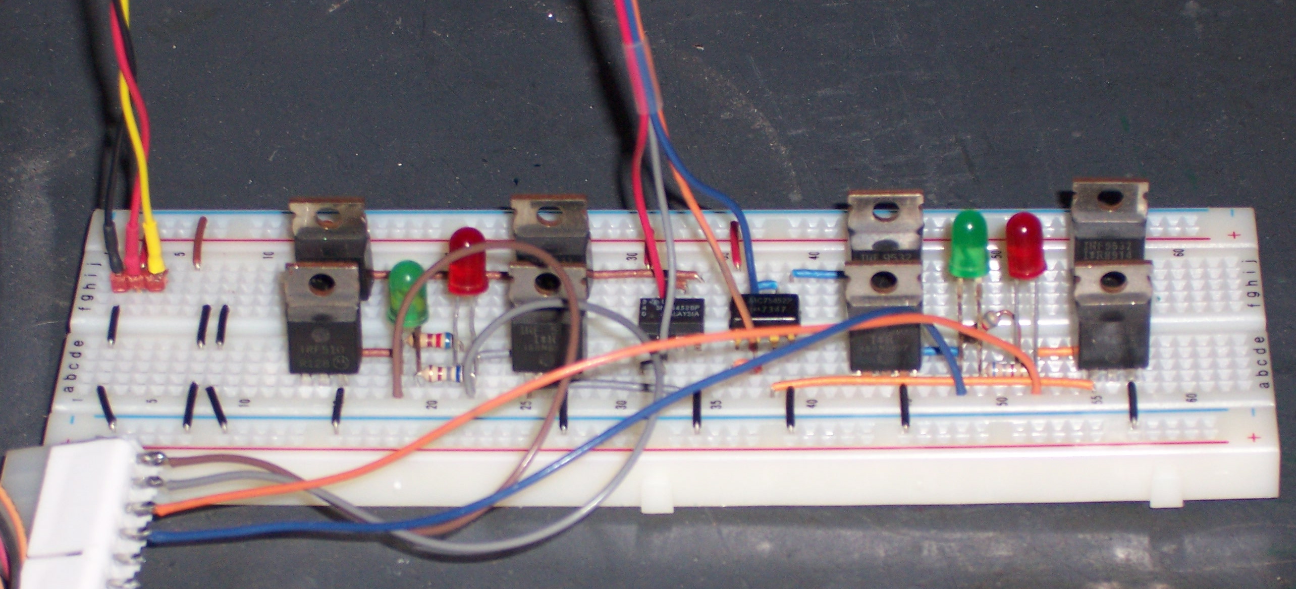
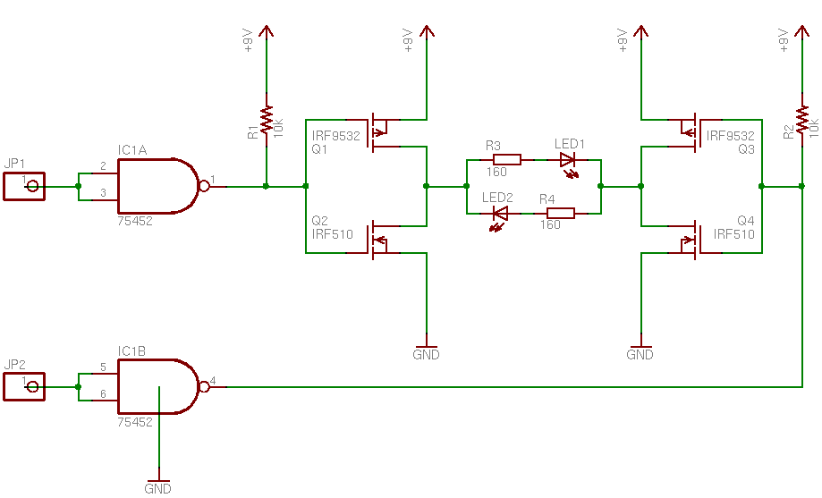
Monday night, I started prototyping with a single IRF510 switching an LED on and off, to make sure I understood basic FET operation. I added an IRF9532 in a half-bridge configuration (the left half of the circuit below), and from their common drains wired one LED high and another low (with resistors, of course), then tested that the LEDs alternated as I applied a square wave to the gates. After demonstrating that the half-bridge worked correctly, I built the full bridge shown below, again testing with LEDs.

MOSFET Stepper Motor Driver Element

Note that the pin numbering on the 75452 is incorrect–EAGLE doesn’t have a definition for the 75452 and I haven’t made one yet, so I subbed a 7400-series chip with open-collector outputs. Now that I think about it, I probably have a 7400-series chip with high-voltage open-collector outputs that I could have used in the circuit instead. I’ll have to keep that in mind.

The Motion

None, of course. A single H-bridge is enough to drive a DC motor; but a stepper needs two, one for each coil. It was late enough, I quit for the evening knowing the bridge was driving LEDs okay, but without testing the motor.

My Uncle’s Iron

May 10th, 2006 by Keith Neufeld

My uncle Adolf is probably most directly responsible for my interest in electronics. When I was growing up, he and Aunt Wanda ran A&W Electronics, retailing and repairing TVs and other equipment. This was back in the days of chassis construction, before circuit boards, when everything was built onto a metal chassis with insulating standoffs, vacuum tubes, lots of wire, and lots of solder.

When they received TVs that were irreparable, he’d often remove the dangerous parts (picture tube, flyback transformer, and huge capacitors) and give the remaining pieces to my brother and me to take apart. Which we did with great zeal, and a couple of wirecutters. I still have boxes of components that we salvaged out of those TVs; and man, they don’t make resistors and capacitors like they used to. And that’s mostly a good thing.

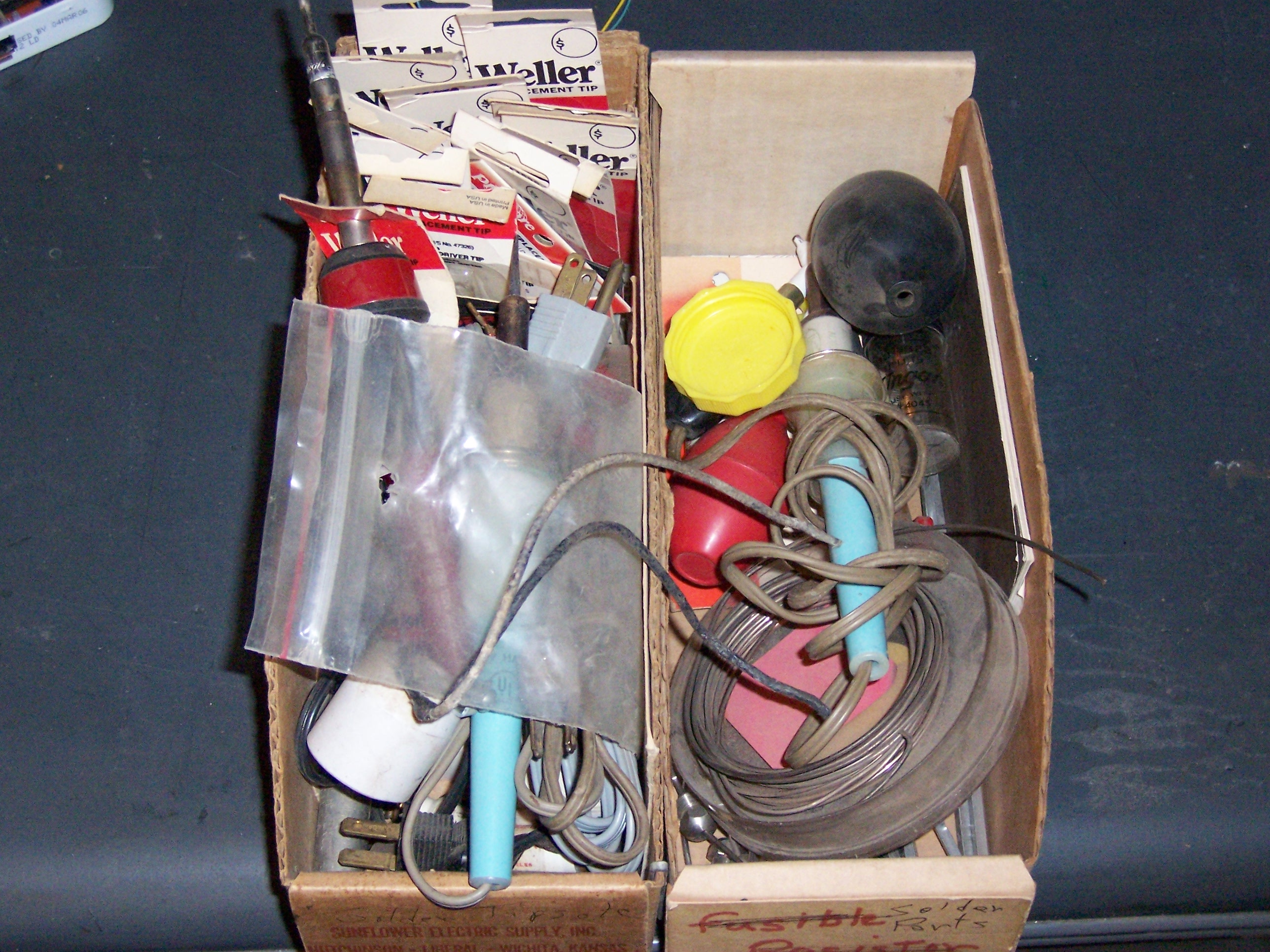
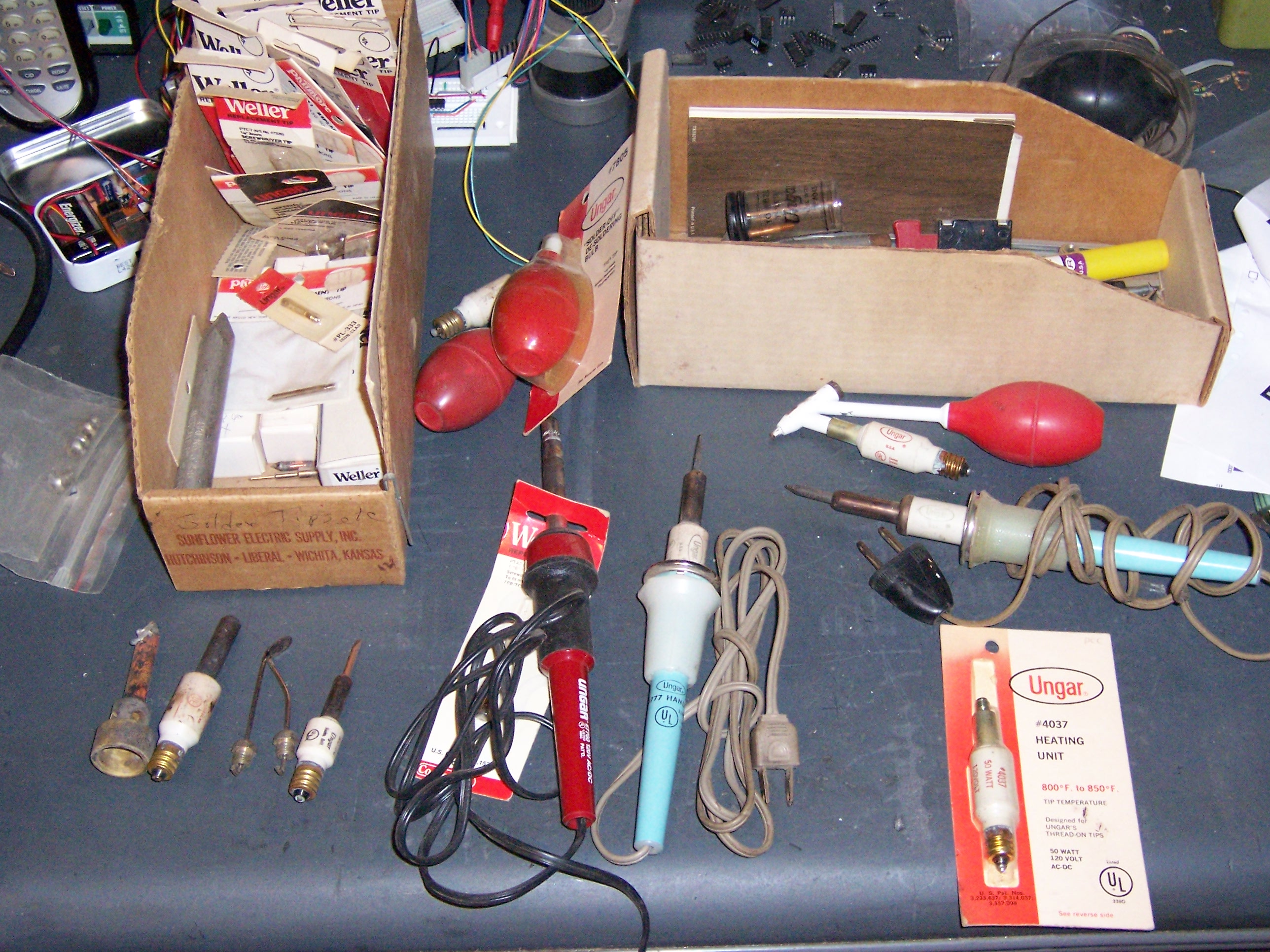
So when they had a household auction recently, in preparation for moving to a retirement community, I was pleased and proud to purchase two boxes of soldering equipment.

Boxes of Soldering Equipment

I could see the Weller/Ungar pencil irons, and knew that any one of them was worth the $16 I paid for the box. It wasn’t until I got home that I could really see what all I got:

Soldering Equipment

There’s just an amazing amount of stuff crammed into the boxes. These irons have replaceable, screw-in heating elements, and the boxes have several spares of different wattages. One or two of the elements have replaceable tips like we’re used to using these days, and there are plenty of spare tips, too. Eventually, I plan to go through everything, sort out what goes with what, and do a little cleaning on the pieces that do fit together–replace brittle power cords, clean iron handles, polish heating elements, etc.

So?

I desolder a lot of components from dead electronic equipment that people give me. I really prefer older stuff with through-hole components, because SMT parts are a pain to identify and sort, and through-hole stuff is easy to prototype and breadboard with. The fastest method I’ve come up with is to pry up crimped leads with a $2 chisel, heat the solder side with a heat gun, and pull the components out with a chip puller or needlenose and drop them into a tub.

Generally.

Except (he finally gets to the point) for the TO-220 MOSFETs on the printer boards. For whatever reason, their through-holes were plated only barely larger than their leads, and I was having a dickens of a time desoldering them with the heat gun. The board was scorching, I was breathing really noxious fumes (and I like the smell of solder flux, but not so much burning fiberglass epoxy), I was bubbling and flexing the board as I pulled on the FETs’ tabs with a pliers, and still no joy. I ended up pulling the entire plated through-holes clean out of the board (um, maybe “clean” isn’t the best word to use here) and sliding them off the transistors afterward with my soldering iron.

And the Iron?

I’ve previously desoldered with soldering irons and guns, and under some circumstances, direct heat can be very effective at removing stubborn leads. So a couple of nights ago, I got around to digging through the auction boxes to see whether I could find a wide tip. I was looking for something that would hit all three transistor leads at once, and I found exactly that–a gimongous .3″ chisel-tip 40W heating element, still sealed in its original bubble package.

I opened the package, cleaned the oxidation off the tip, screwed it into one of the handles, and plugged it in. When it started getting up to temperature, I smiled in appreciation at the ceremonial first tinning of the new tip. I grinned at its extreme shininess as I wiped off the solder on the damp sponge. I dropped my jaw in amazement as the transistor slipped right out of the board in about a second of applying the tip to the leads. I desoldered the remaining thirty or so transistors in a matter of brief minutes.

The tip kept heating up the whole time. As I was finishing, I would occasionally cast shadows on the iron and see that the tip was now red-hot. I’d wipe it on the damp sponge and see little embers rise into the air as it tore off and burned rough parts of the sponge surface. I was rather unnerved to see this from an element rated at 40W.

But boy, did it desolder them transistors! Yee-haw!

Obligatory FPS Reference

I’m somehow reminded of the differing effectiveness of various weapons against various monsters in Doom. When you run into a cacodemon, you better make sure you have the nailgun handy–even though it’s utterly useless against several other species.

Stepper Motors, Part II: Testing Motion

May 10th, 2006 by Keith Neufeld

The Wiring

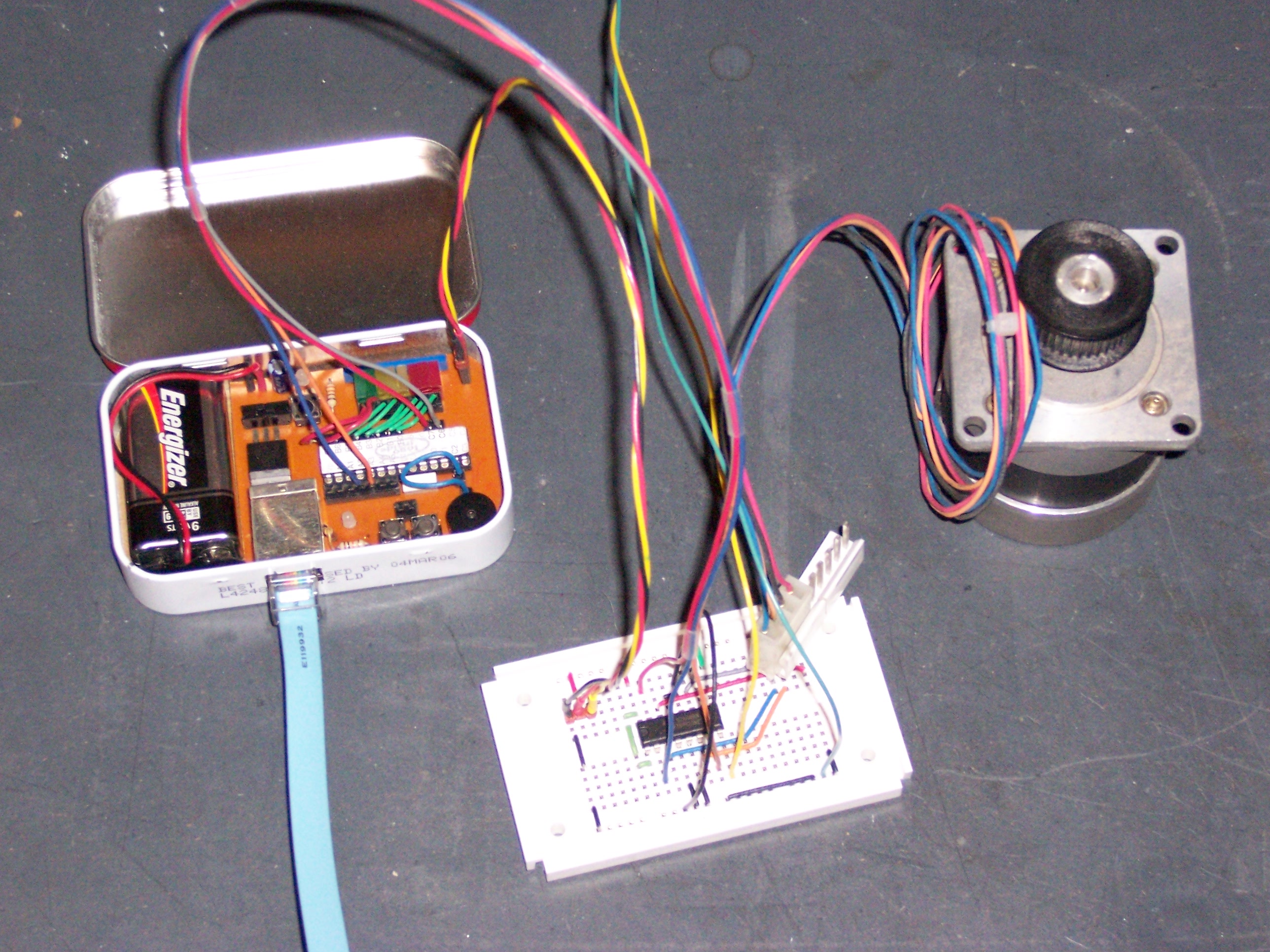
Sunday, worked in around the community orchestra concert, I got the stepper motor moving using my old friend, the 754410 dual H-bridge driver. I hooked each coil across an H-bridge, and used my Curiously Strong LogoChip as a controller, with two pins running each bridge (forward and reverse). Four pins per motor may or may not be the best way to build a complete CNC machine, but it worked nicely for testing.

Stepper Motor with LogoChip Controller and 754410 Driver

The red/yellow/black wire set from the LogoChip to the driver board provides regulated 5V and unregulated 9V to any auxiliary circuits I want to connect–I like to think of it as the PTO. The red/grey/blue/orange wires from the LogoChip to the driver board are the step control signals, and the red/black/blue/orange wires are permanently cabled into the motor. The yellow/green wires feed from one of the variable outputs on my bench power supply, and provide drive power separate from logic power, to keep dips and noise due to the motor from interfering with the logic control circuitry.

The Software

After wiring up the driver board, I wrote a little LogoChip program to control the driver. I needed to provide a quadrature-encoded signal (one goes high, two goes high, one goes low, two goes low) on two sets of two pins, and be able to reverse it. It turned out to work really nicely to modularize the CW/CCW quadrature code in one function, and put the icky code to deal with turning pins on and off in a separate function–it makes the quadrature code reusable to run multiple motors, among other things.

Here’s what I ended up with:

  • stepper.txt – Program to drive bipolar stepper motor

Here’s the code:

;   stepper.txt
;
;   06-May-2006  Keith Neufeld
;
;   Test/drive bipolar stepper motor, using external 754410 driver chip.
;   Two coils are driven in quadrature:
;
;       ===|       |=======|       |=======|       |=======|
;          |       |       |       |       |       |       |
;          |=======|       |=======|       |=======|       |===
;
;       =======|       |=======|       |=======|       |=======|
;              |       |       |       |       |       |       |
;              |=======|       |=======|       |=======|       |

;------------------------------------------------------------------------------
;   Debug system
;------------------------------------------------------------------------------

constants [[debug 0]]
;constants [[debug 1]]

;------------------------------------------------------------------------------
;   Section to manipulate stepper motor.
;   Coil 1 driven by C7/C6.  Coil 2 driven by A2/A3.
;------------------------------------------------------------------------------

constants [
    [coil1-port portc] [coil1-ddr portc-ddr]
    [coil1a-bit 7] [coil1b-bit 6]

    [coil2-port porta] [coil2-ddr porta-ddr]
    [coil2a-bit 2] [coil2b-bit 3]
]

to stepper-off
    clearbit coil1a-bit coil1-port      ;   set all coil outputs low
    clearbit coil1b-bit coil1-port

    clearbit coil2a-bit coil2-port
    clearbit coil2b-bit coil2-port
end

global [steps-per-sec msec-per-step]    ;   timing "constants"
global [coil1-pos coil2-pos]            ;   current coil state

to init-stepper
    stepper-off                         ;   shut down all coil outputs

    clearbit coil1a-bit coil1-ddr       ;   set all coil pins as outputs
    clearbit coil1b-bit coil1-ddr

    clearbit coil2a-bit coil2-ddr
    clearbit coil2b-bit coil2-ddr

    setsteps-per-sec 2                  ;   2 steps per second
    setmsec-per-step 1000 / steps-per-sec       ;   precalculate wait per step

    setcoil1-pos 0                      ;   initialize quadrature to (0,0)
    setcoil2-pos 0
end

to step-set                             ;   push out new quadrature values
    ifelse debug [
        send 48 + coil1-pos             ;   0/1 with no CR
        send 32                         ;   space with no CR
        print coil2-pos
    ] [
        ifelse coil1-pos [
            clearbit coil1b-bit coil1-port      ;   clear before set
            setbit coil1a-bit coil1-port
        ] [
            clearbit coil1a-bit coil1-port      ;   clear before set
            setbit coil1b-bit coil1-port
        ]

        ifelse coil2-pos [
            clearbit coil2b-bit coil2-port      ;   clear before set
            setbit coil2a-bit coil2-port
        ] [
            clearbit coil2a-bit coil2-port      ;   clear before set
            setbit coil2b-bit coil2-port
        ]
    ]
end

;   CW pattern:
;       0110.0110
;       0011.0011

global [new1 new2]                      ;   temps for coil values

to step-cw
    setnew1 not coil2-pos
    setnew2 coil1-pos

    setcoil1-pos new1
    setcoil2-pos new2

    step-set                            ;   do it
end

to step-ccw
    setnew1 coil2-pos
    setnew2 not coil1-pos

    setcoil1-pos new1
    setcoil2-pos new2

    step-set                            ;   do it
end

;------------------------------------------------------------------------------
;   Routines to tie it all together
;------------------------------------------------------------------------------

to init-all
    init-stepper
end

to powerup
    init-all
end

to startup
    init-all
    loop [
        step-cw
        mwait 100
    ]
end

The Movement

I started up the motor control with a loop [ step-cw wait 10 ] from the LogoChip console, then turned up the variable power supply until the motor was chunking along at a step per second. That channel of my power supply is only good for 1.5A, and I found that no matter how high I turned the dial, the meter didn’t read any higher than about 2.5V. I guess the coil power calculations were pretty close.

Next, I played with different timing values, to watch the motor turn at different rates and test its torque. I found that on this power supply, I could very easily stop or spin the motor contrary to the control signal. That was a little disappointing, but I realize also not at all a fair test, with the motor so underpowered.

Finally, I knew the 754410 is only rated for 1A per bridge, and I was attempting to use it for much more than that. I was being careful not to sustain high-voltage testing for long periods, but I was still curious how the 754410 was reacting thermally. The result was fascinating–I could quite distinctly feel the chip getting warmer as I ran the motor and cooler when I stopped it. I’m used to components heating up, but I’ve never before experienced it so directly in real time (at least, not without scorching my fingers).

I had known that the 754410 wouldn’t be my ultimate drive circuit, but I hadn’t known I would hit the wall with it so quickly. After realizing how hot it was running, I knew the next step was building a drive circuit with discrete power transistors. And I just happened to have some on hand: MOSFETS, from the stepper drivers in some old printers.

Review time in my Malvino–quite possibly the best $130 I ever spent.

Stepper Motors, Part I: Confirming Values

May 6th, 2006 by Keith Neufeld

The Project

My friend Joel has a computer numerically controlled (CNC) drilling machine that he built from a mail-order unpopulated circuit board and a set of plans. Its table holds materials up to about 10″ x 14″, and I go over to use it any time I need to drill a circuit board. It’s not terribly inconvenient to use his, and it’s always a nice excuse to visit with him while we’re setting it up and letting it run–but I’ve wanted my own for as long as I can remember. They’re just cool.

There are lots of descriptions of and plans for CNC drilling machines on the Web, so I won’t go into a lot of detail. The basic idea for this model, though, is that a drill is suspended in place above a table that slides around to position the workpiece. The table is positioned by long screws (all-thread) turned by stepper motors, which are motors that move small increments (steps) in response to an input signal, rather than running freely. Each step is a small fraction of a complete rotation, and coupled with the worm-drive effect of the lead screw allows for very precise positioning of the workpiece–easily 1/1000″, and often 1/8000″. (Of course, mechanical issues like backlash do intrude, but 1/1000″ doesn’t seem to be terribly hard to achieve.)

The Motors

So . . . I want to build my own CNC drilling/milling machine, and since I do electronics bottom-up, the project starts with the motors. And boy, do I have motors. I have these giant steppers out of heavy-duty wide-carriage impact printers from a former employer just begging to be used.

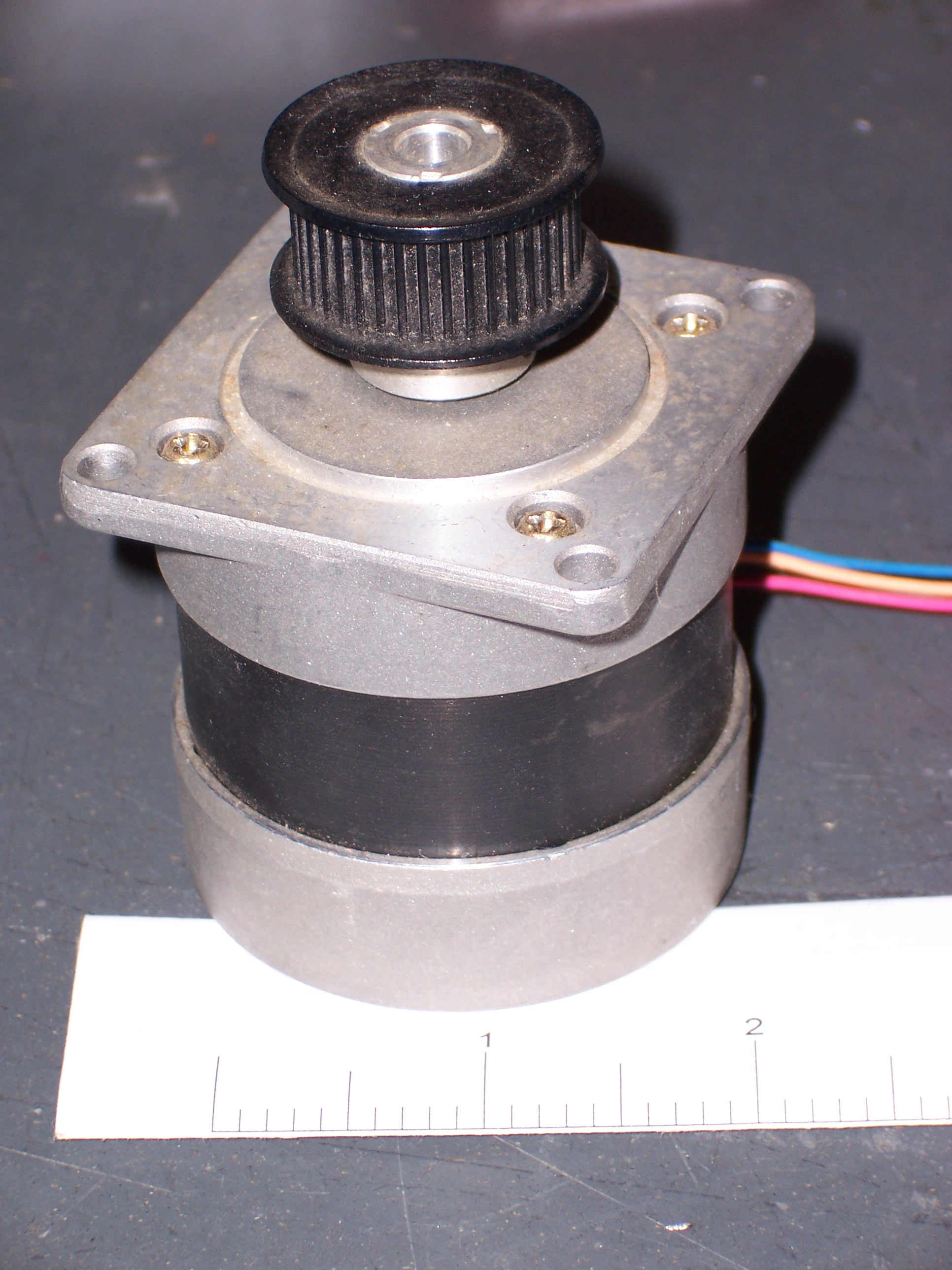
Big Stepper Motor

If you look carefully, you can see the ruler underneath the motor–it’s a good 2″ in diameter. Pretty heavy, too.

As we wrapped up our TechArt installation, my thoughts have been returning to these motors, and wondering what it would take to start building drivers for them. This weekend, in between community orchestra rehearsals, I sat down with one of the motors and started making notes. Here are the specs from the sticker on the back side:

PULSE MOTOR
TYPE PJ55E1U97A

A / Phase: 2.5
Ω / Phase: 0.85

Nippon Pulsemotor Co Ltd

Uh, .85Ω per phase? Are they kidding??? That’s an insanely low coil impedance compared to what I’m used to on traditional motors. I can see already this is going to be a challenge.

The Coils

The first thing to do with an unknown stepper motor is figure out the coil wiring. Steppers have multiple coils, each determining either one or two rotor positions, and each with an external wire or pair. From the steppers I’ve played with, four wires generally means two coils each powered in alternating directions, five wires is one common plus four unidirectional coil connections, and six wires is three unidirectional coils. This motor has four, so it was a simple check with an ohmmeter to determine which wires go to which coils.

Red to black: 1.3Ω
Orange to blue: 1.2Ω

Internal resistance of meter (shorting probes together): .3Ω
Variation due to probe placement and pressure against pins: up to .2Ω

So yeah, that’s pretty much .85Ω per coil. Wow.

The label says 2.5A per coil. To get 2.5A current, 2.5A * 1Ω = 2.5V and 2.5A * .85Ω ≡ 2.1V. That’s a really low coil voltage, given some assumptions I’ve already made about the drive circuitry, so I can tell that’s going to be a challenge.

Finally, I hooked wires to my bench power supply and touched them to the coil wires, just to watch the rotor move. In that very unscientific experiment, it looked like the stepping behavior (speed and impact of single steps) was about the same when using a 5V supply as when using a 2.5V supply. That gave me hope that I might be able to fudge on the details and use a higher coil voltage than nominal–although I don’t want to heat up the motor and melt the coils during intense use.

The step pattern I tried moved the motor CCW: black/red, blue/orange, red/black, orange/blue.

Craft to Art; Construction to Exhibit

April 26th, 2006 by Keith Neufeld

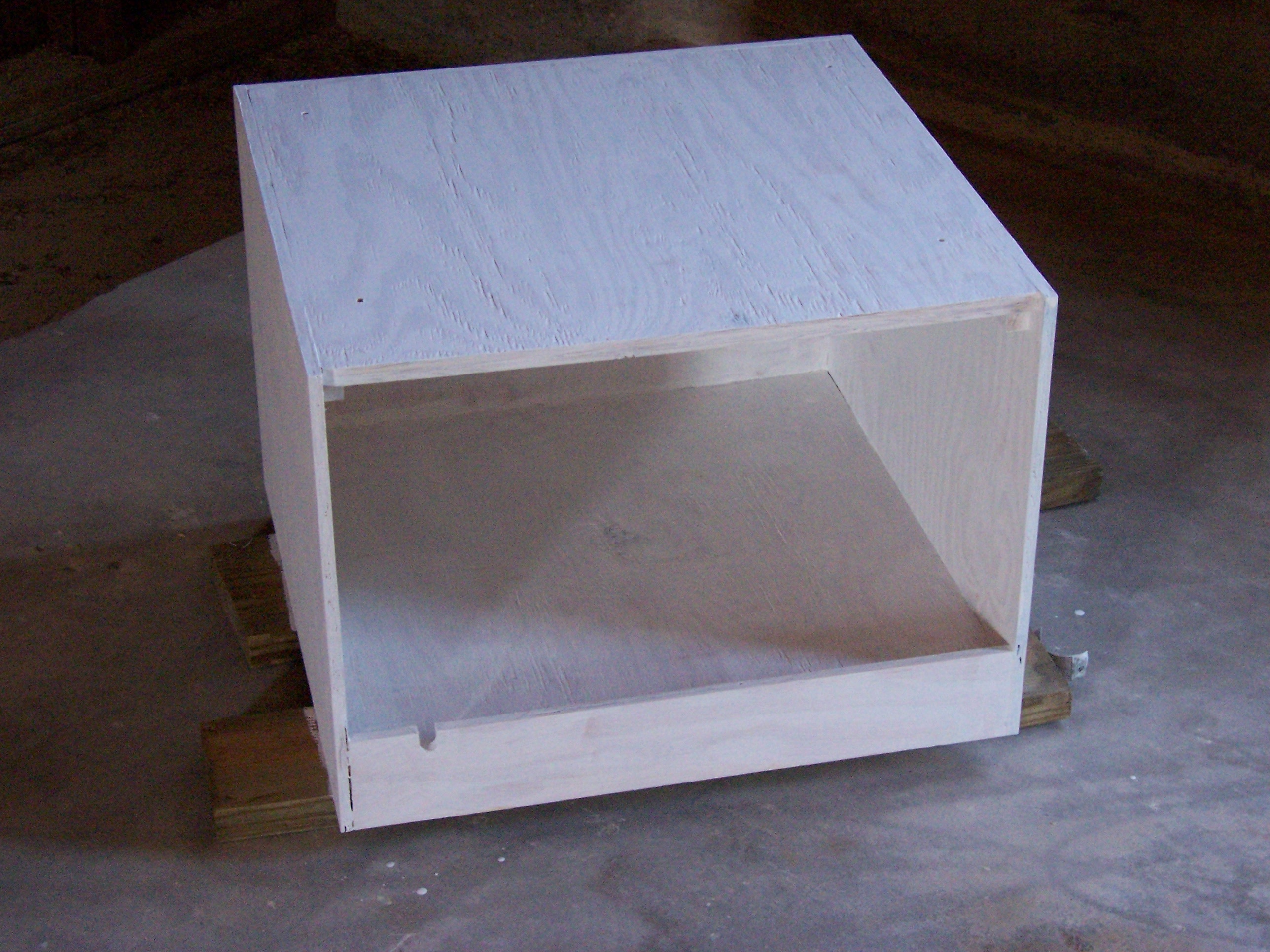
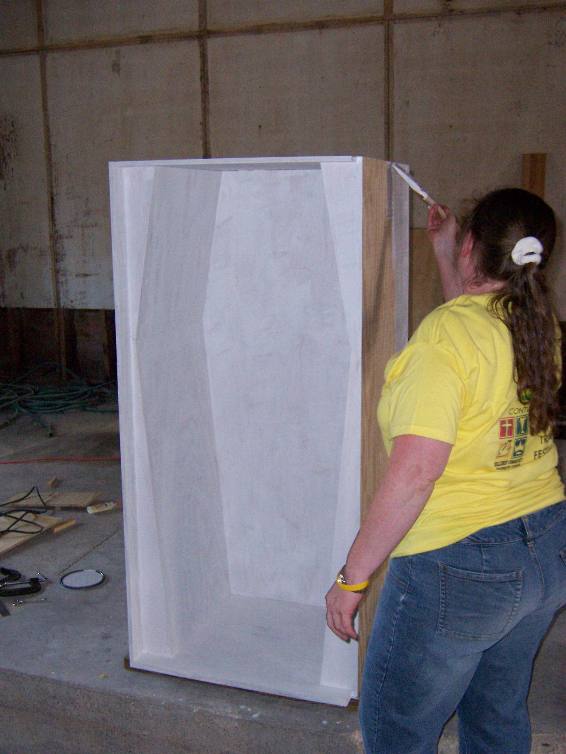
Andrea’s doing an amazing job prepping the cabinet for display. While I was painting the primer, the cabinet looked white and ucky like this:

And here’s my wife helping on the first coat:

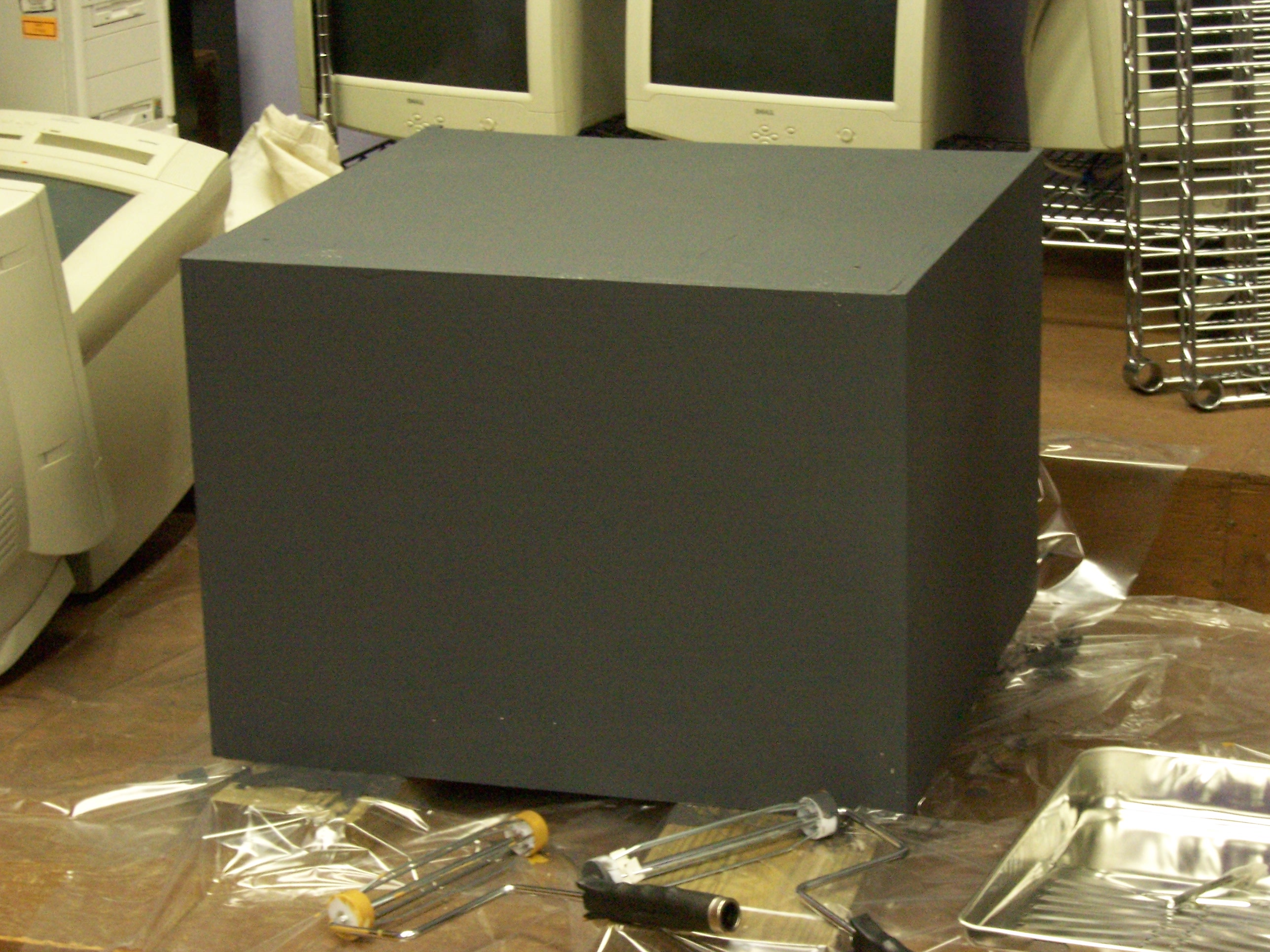
But bring it to someone with vision and you get a sweet-looking flat grey base coat on the outside:

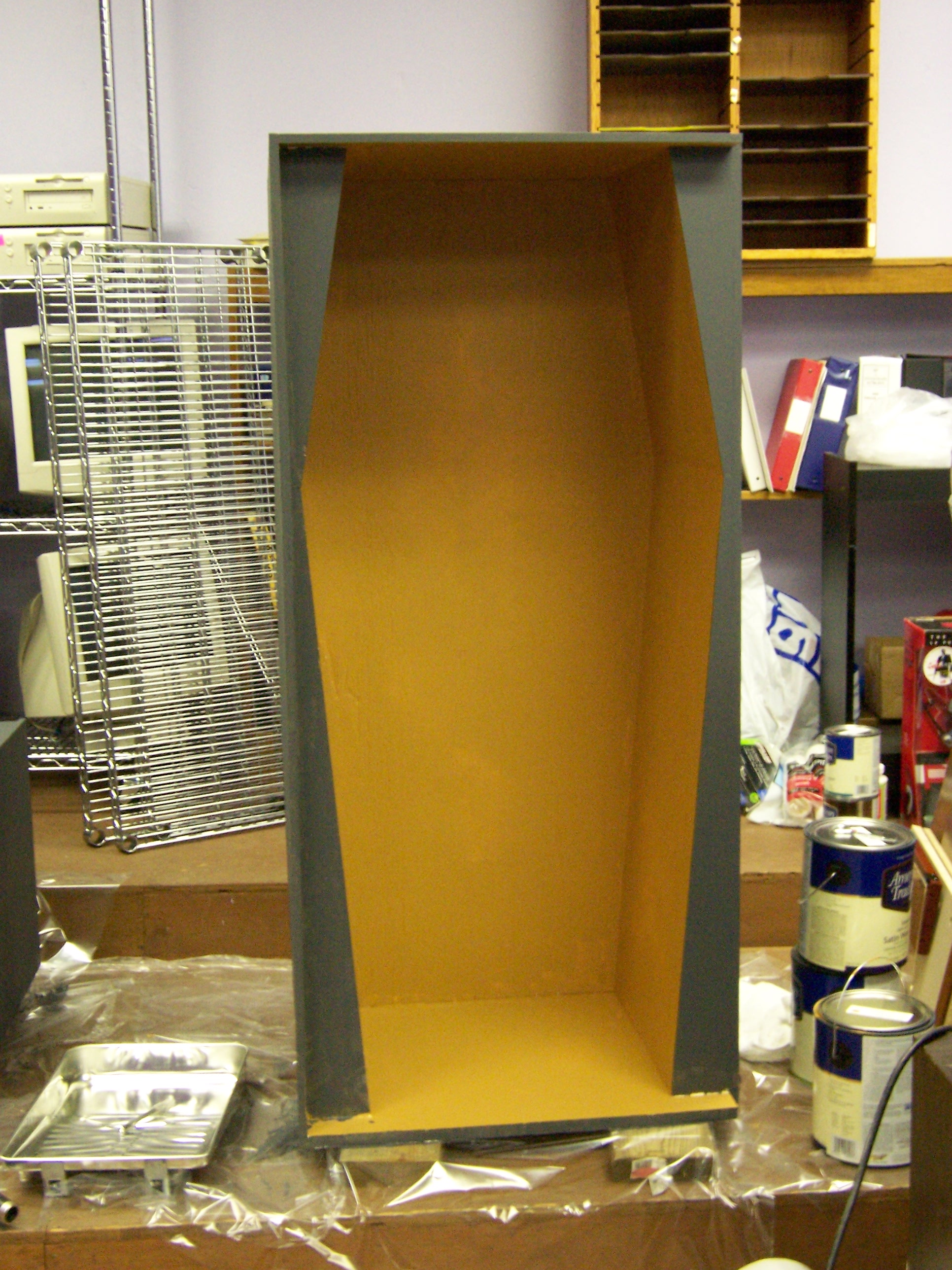
And a “camel” color on the interior that really makes the coffin shape pop:

Andrea has also “bagged” (sponged) on some bronzing, which looks great:

And I can hardly wait to see the pink (fuschia?!) that comes next, with a crackle coat to follow. Sweet!

Ultrasonic Rangefinder, Part III: Receiver / LogoChip Interface Attempt

April 26th, 2006 by Keith Neufeld

I haven’t touched the DIY rangefinder project for a couple of weeks, but I realized I also never wrote up my latest work on it.

Receiver Comparator

After my previous post about building two amplifier stages, I intended to use one of the spare channels on the LM324 as a comparator to “digitize” the amplified receiver signal and provide a clean input to the LogoChip. Unfortunately, the first time I prototyped it was late in the evening when my brain doesn’t work too well, and I built it just like the first two stages–as a linear amplifier. I was really surprised to see more analog waveforms on my scope when I expected sharp edges. At only 24kHz, I didn’t think it should be a slew rate problem, but I wasn’t thinking clearly and just set it aside for the night.

The next day, my error was obvious, and I pulled out the feedback resistor to let the op amp run open loop with infinite gain. It cleaned up the signal, although still not as much as I would have expected. Once the basic circuit was working, I replaced the fixed voltage divider with a 20k trimpot and tuned it as well as I could, trying to find the sweet spot to weed out all the noise but pass all the real signals.

I hadn’t seen it before, but now I wondered whether I was getting some false readings from noise, as John suggested he had encountered when working on similar circuits. I looked briefly at adding a low-pass filter to the circuit (it’s already high-pass filtered by the capacitive coupling from the receiver to the first amplifier stage due to the single-ended op-amp I’m using), but haven’t done it yet. First I wanted to connect it to the LogoChip and see what kind of results I got.

PIC CCP

An ultrasonic rangefinder measures distance by emitting a “ping” and counting the time until the echo is detected; dividing by the speed of sound translates the round-trip time into a distance. Because of the short durations involved, the easiest way to do this on a PIC microcontroller is with the “capture” section of the Capture/Compare/PWM (CCP) subsystem. It uses a high-resolution timer and interrupt circuitry to give a very precise measurement of how long something takes to happen.

I started with John Harrison’s CCP code from his srf_demo.txt example on the TechArt wiki LogoChip with Ultrasonic Sensor page. His code was using the PIC’s CCP module #1; but in my application, I was already using CCP1 to provide the 24kHz signal for my transmitter, so I started translating to use CCP2. The control and behavior of the two CCP channels are rather different, so it wasn’t a matter of simple substitution. Here’s what I ended up with:

Here’s the receiver section of the code:

;------------------------------------------------------------------------------
;   Routines for manipulating CCP2 and timer 3 for capture.
;------------------------------------------------------------------------------

constants [
    [CCP2CON $fba]                      ;   capture/compare/PWM 2 control reg
        [CCPxM-CAP-EVERY #0100]                 ;   capture every falling edge
    [CCPR2H $fbc]                       ;   CCP 2 register low byte
    [CCPR2L $fbb]                       ;   CCP 2 register low byte
    [PIR2 $fa1]                         ;   peripheral interrupt request 2
        [CCP2IF 0]                              ;   timer 3 interrupt bit
    [CCP2-PORT portc]                   ;   uses portc pin 1
        [CCP2-BIT 1]
    [CCP2-DDR portc-ddr]

    [T3CON $fb1]                        ;   timer 3 control register
        [T3CCP2 6]                              ;   timer 3 CCP mode bit 2
        [T3CCP1 3]                              ;   timer 3 CCP mode bit 1
                                                        ;   1x src CCP1+2
                                                        ;   01 src CCP2
        [T3CKPS1 5]                             ;   timer 3 prescale bit 1
        [T3CKPS0 4]                             ;   timer 3 prescale bit 0
                                                        ;   11 = 1:8
        [TMR3ON 0]                              ;   timer 3 enable bit
    [TMR3H $fb3]                        ;   timer 3 high byte
    [TMR3L $fb2]                        ;   timer 3 low byte
]

;   Initialize CCP by configuring timer 3 and enabling capture mode.
to ccp-init
    write CCP2CON CCPxM-CAP-EVERY       ;   config to capture every falling edge

    clearbit T3CCP2 T3CON               ;   set T3CCP to 01 to make T3 src CCP2
    setbit T3CCP1 T3CON                 ;       and T1 src CCP1

    setbit T3CKPS1 T3CON                ;   set T3CKPS to 11 to use 1:8
    setbit T3CKPS0 T3CON                ;       prescalar

    setbit TMR3ON T3CON                 ;   enable timer 3

    setbit CCP2-BIT CCP2-DDR            ;   set CCP2 (RC1) pin for input
end

;   Record starting value of timer 3 and clear capture flag.
global [ccp-before]
to ccp-start
    setccp-before ((read TMR3H) * 256) + read TMR3L
    clearbit CCP2IF PIR2
end

;   Wait for capture event and return duration.
global [ccp-after]
to ccp-wait
    waituntil [testbit CCP2IF PIR2]     ;   wait for capture interrupt
    setccp-after ((read CCPR2H) * 256) + read CCPR2L
    output ccp-after - ccp-before
end

I added code to send a ping and take a measurement:

;------------------------------------------------------------------------------
;   Top-level routines to tie it all together.
;------------------------------------------------------------------------------

;   For the sake of testing, activate on powerup.
constants [[standalone 0]]
to powerup
    pwm-init
    ccp-init
    if standalone [ pwm-on ]
end

;   Send a short burst of tone.
to ping
    pwm-on
    mwait 1
    pwm-off
end

;   Ping and measure time to reply.
to range
    ccp-start                           ;   record start time
    ping
    output ccp-wait                     ;   wait for echo and return duration
end

Wrote a little loop to display the results on the PC, and was disappointed to see that they really didn’t vary at all in proportion to the distance from the sensor to an obstacle. After a few minutes of head-scratching, I noticed that I hadn’t wired the comparator output to the LogoChip’s CCP input. Oops! And that’s when I realized I had a much bigger problem.

Overloading Port C1

The PIC’s CCP modules are implemented in hardware, and they’re hard-wired to specific pins. The input pin for CCP2 is the same as general-purpose pin C1–in fact, most if not all of the PIC’s pins have multiple functions that are selected by configuration registers.

My problem arose because C1 is already being used by the LogoChip firmware–as the Go/Stop input! Because LogoChip Logo isn’t open-source, I can’t see exactly how it’s being used, and have to guess what would happen if I tried to use it as a capture input. Since pressing a button attached to that pin makes the LogoChip stop executing user code and return to an idle state, I can’t imagine I’d have an easy time overriding that behavior and getting it to use the pin solely for CCP with no interference.

So what now? I need both CCP modules–one to use the PWM output to drive the 24kHz transmitter, and the other to watch and count time on the receiver. I don’t think I’ll be able to overload C1 with CCP2 for the receiver, so I’m left with a couple of options: swap the pins, or use CCP1 for both transmission and reception.

Swap the Pins

My first thought was to use CCP1 as the receiver (since its corresponding port, C2, is otherwise unused) and make CCP2 the transmitter (on port C1, the Run/Stop button). John says he has previously overridden C1 and used it as an output when the Run/Stop functionality wasn’t needed, so this should work.

In the long run, though, I’m a little uncomfortable giving up the Run/Stop button. I’d like to be able to integrate this technology into hobby robots, and I’d like to be able to leave them powered up but in an idle state, without having to duplicate the preexisting Run/Stop behavior myself in software. Swapping the PWM-transmit / capture-receive pins should work for a quick fix, but I’m not sure it’s where I want to be in the larger game.

Use CCP1 for Both Transmission and Reception

Alternately, I could overload CCP1 for both transmitter and receiver. There’s precedent–another student in class is using the Parallax PING))) (TM) sensor module, which has only three pins–ground, power, and bidirectional signal.

To do that, I’d need to make sure that transmission and reception don’t interfere with each other. Keeping transmissions out of the receiver circuit is easy–put a diode from the comparator output to the LogoChip so the transmitter signals don’t go “upstream” into the comparator.

Keeping comparator signals out of the transmitter driver is a little trickier, but I think I have a reasonable solution, based on something I was considering doing anyway. I’d like to be able to drive multiple sensors from one LogoChip, but there’s only one (er, two, maybe, sorta) PWM output available. To drive multiple rangefinders, I’d need to multiplex the PWM signal somehow–and there are plenty of ways to do that.

The most straightforward is to use a few LogoChip output pins to select which transmitter to drive and AND (or NAND) them with the PWM signal. Cake! And it tidily solves my receiver-interfering-with-transmitter problem–the receiver can dump whatever it wants onto the PWM output, but it won’t go anywhere harmful unless one of the transmitter select lines is activated.

Sounds like a win all around, and I think I’ll investigate it as soon as things calm down with the exhibit and I can get back to tinkering. It means a little more work on the software side (switching CCP1 back and forth between PWM and capture modes), but I’ve never been afraid of writing code.