Archive for the ‘Miscellaneous’ Category

PCB Iron-On Etch Resist Problems (and Solutions)

Monday, August 6th, 2007

After drilling my board (and finally getting the right holes in the right order), I took it back home to etch. I wanted to print an etch-resist mask on my laser printer and iron it onto the board, and I wanted to do it using plain, glossy paper.

Pads and Holes

I had originally laid out the board using default sizes of 28 mil holes and 50 mil pads. Since I broke too many drill bits and ended up drilling with a 39 mil bit, that would have left me only 5.5 mils of copper surrounding each hole. That’s not nearly enough to solder to, much less enough to consistently align with an iron-on transfer. I went back into FreePCB and increased all the pad sizes to 70 mil, to give about 15 mil of copper around each hole.

Lesson: Keep a good supply of small drill bits.

Lesson: Don’t bump up to larger drill bits if you run out of small ones. Wait for more of the right size.

Lesson: Use larger pads than default when laying out a board for iron-on transfer.

Ironing in Pieces

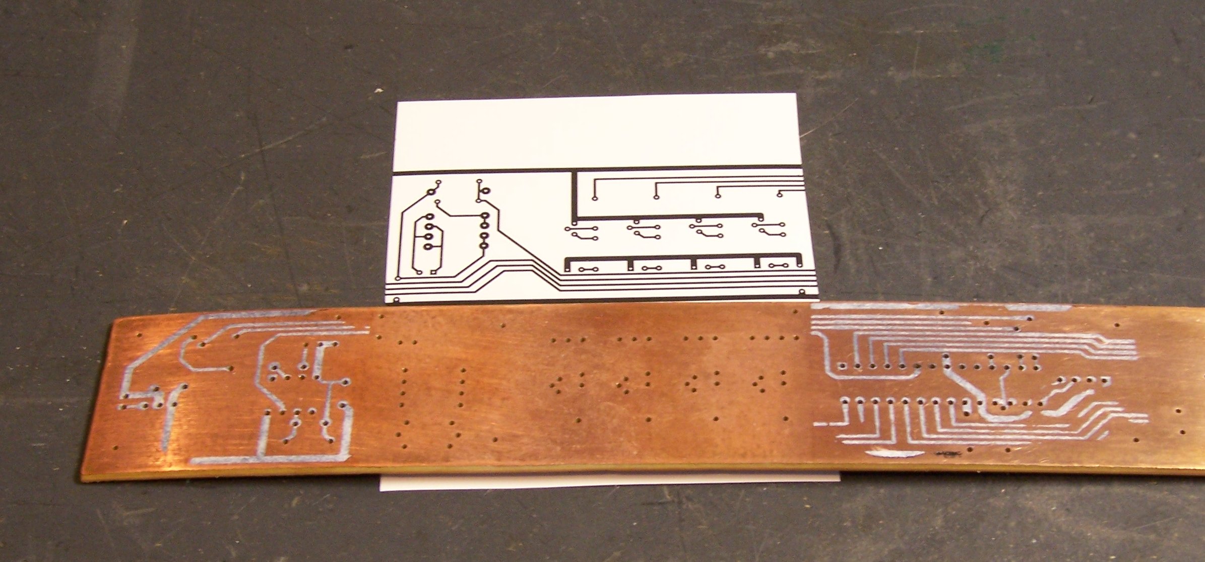
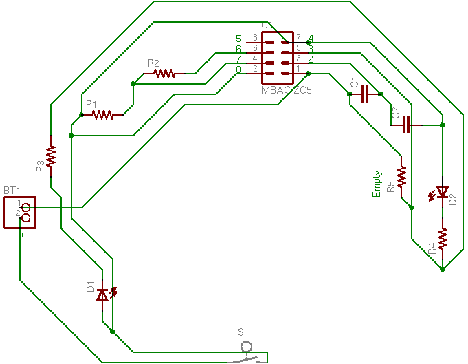
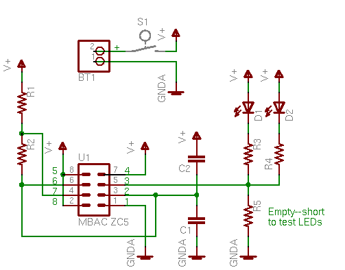
Once I had increased the pad size, I exported the bottom copper layer as an image file. (FreePCB doesn’t seem to have a working Print function.) Because the bottom layer is drawn from the perspective of the top of the board, one would normally mirror it to view how it would look from the bottom. But the iron-on process reverses the image, so I needed to print it unmirrored.

Lesson: Export/print the bottom copper layer unmirrored when making iron-on transfers.

Because the 16.8″ length of my PCB was greater than the size of paper my printer accepts, and because the printer doesn’t seem to print at exactly accurate size, I used the GIMP to chop the image into three pieces, to iron on in sections. I split the image in areas with no holes and all horizontal traces so it’d be easy to line up, and I left about 1/4″ of overlap at each joint so I’d double up toner on the board rather than taking any chance of having a gap.

Ironing laser toner onto a PCB for etch resist, in sections

I ironed the two outer sections onto the board using our household iron set at 350°F and no steam, then soaked the board for half an hour to soften the paper and carefully peeled it off.

Iron-on PCB toner transfer with poor adhesion

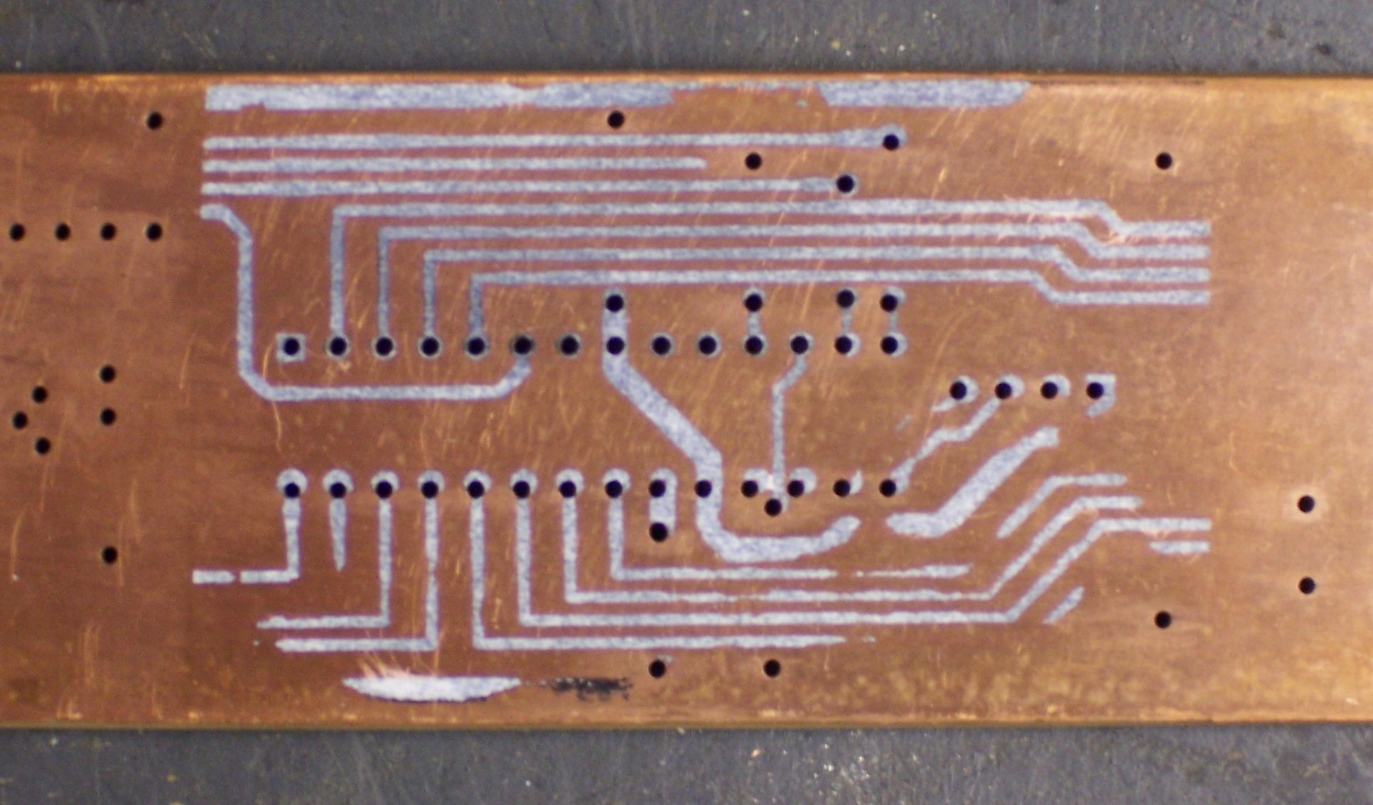
A lot of the traces came off with the paper. It didn’t feel like I had peeled the traces off the PCB — it felt like they had never adhered in the first place. Reinforcing that suspicion was how much effort it took to clean the traces off the board and start over — the ones still on the board were well stuck. I ended up using acetone to clean them off the board.

I printed another copy and ironed it on, using the maximum temperature on the iron and the Giles Corey method (more weight). This time I soaked the board for over an hour. Once again, large sections of traces peeled away.

Press ‘n’ Peel Blue and Successful Ironing

I have a few sheets of Press ‘n’ Peel Blue that Joel bought and encouraged me to test drive, and I’d had reasonably good luck the previous time I tried them, so I got them out. To avoid wasting an entire sheet of Blue, I printed the design onto a carrier sheet of plain paper, then cut appropriate-sized sections of Blue and masking-taped them to the paper over the printed areas and printed again.

Press 'n' Peel Blue

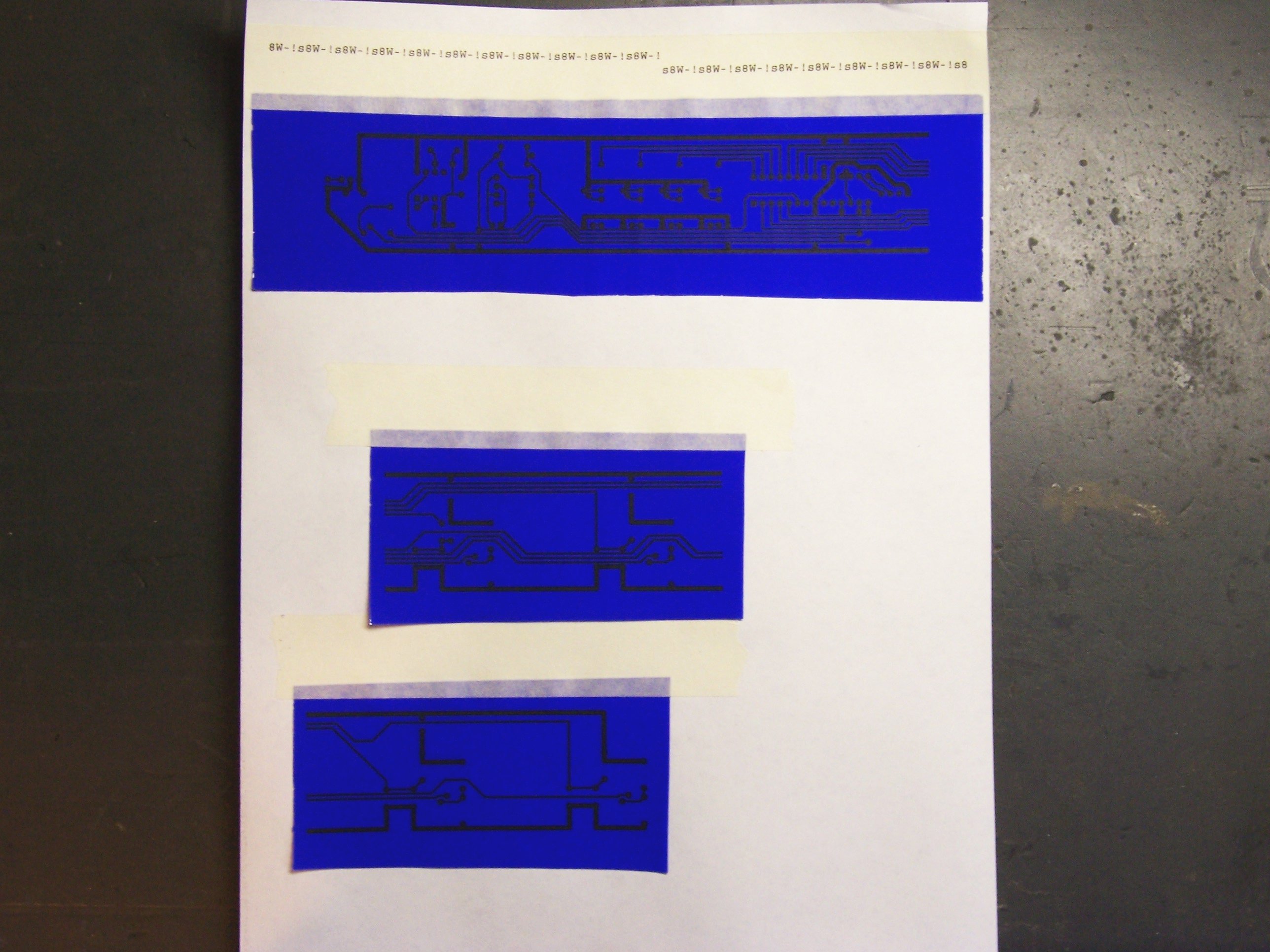
You can see across the top where my printer went nuts printing PostScript source code on the first try, but I got the design printed onto the Blue on the second try. I ironed a section of Blue onto the freshly-scrubbed PCB board, and . . .

Press 'n' Peel Blue iron-on PCB transfer; no adhesion around holes

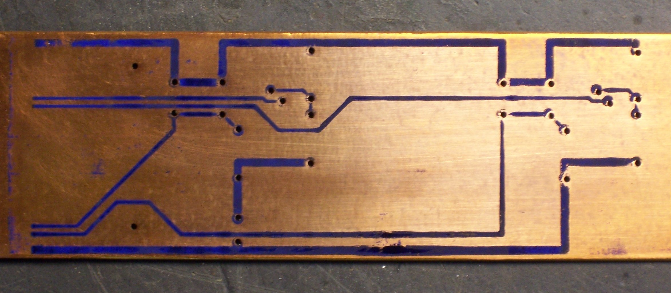
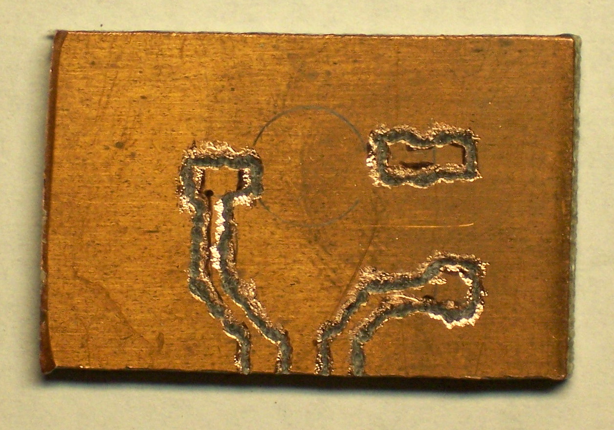
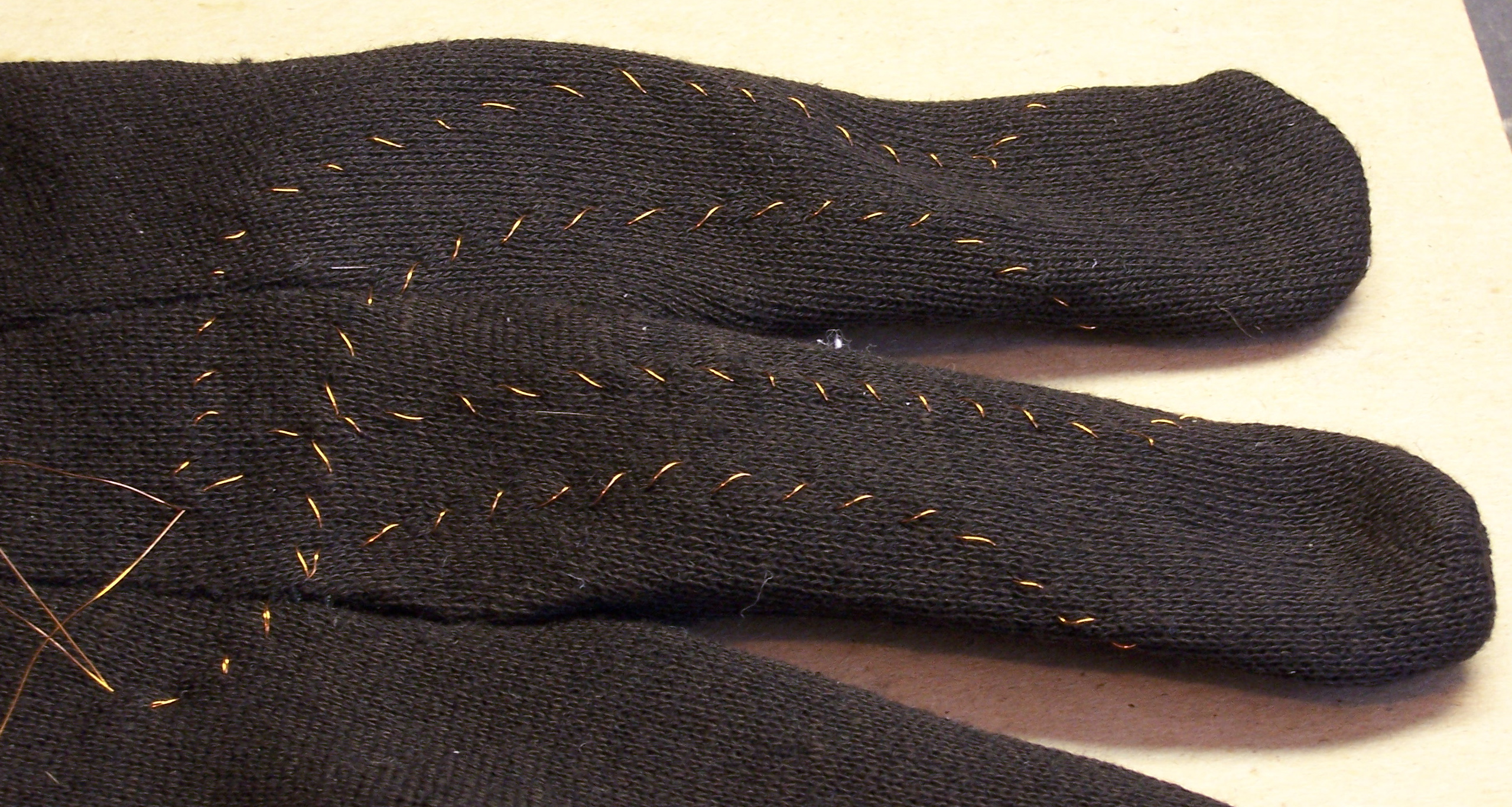
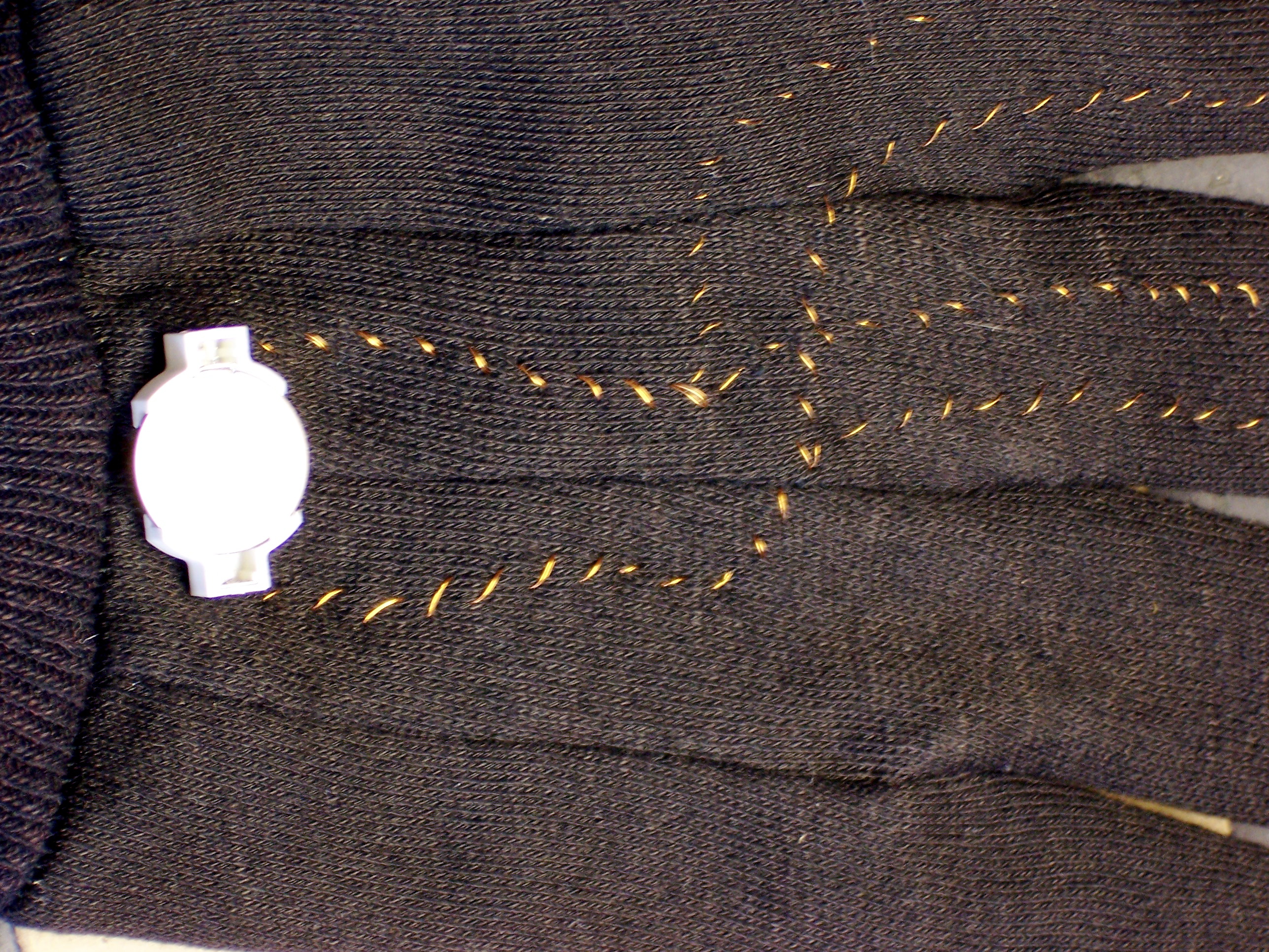
Excellent adhesion most places; terrible adhesion around the holes.

So what’s different about the holes? I think they’re dimpled from when the drill hits the copper and before it starts to bite. The surface is slightly lower, and there’s not enough pressure to adhere the Blue (or the plain-paper transfer) to the copper.

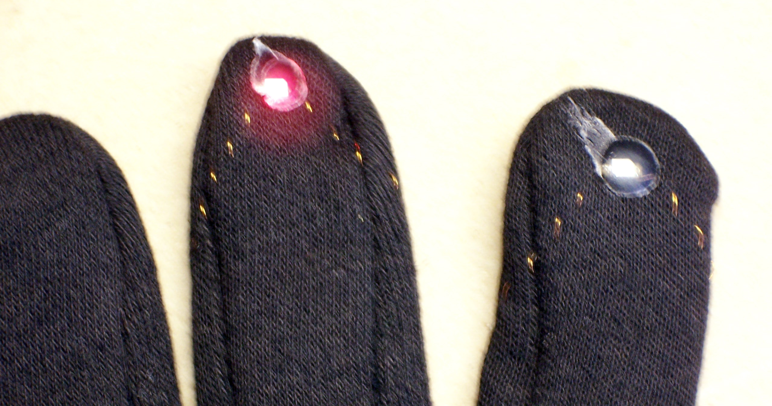
I needed something between the iron and the transfer to help distribute the pressure, even down into slight surface variations. I considered a sheet of felt, but I was afraid that it would be too soft to distribute the pressure well. I settled on a kitchen paper towel folded in half, and voila!

Press 'n' Peel Blue iron-on PCB transfer; good adhesion throughout

Good adhesion everywhere!

Lesson: Use a thin pad between the iron and the toner transfer to help distribute pressure through surface irregularities.

Etching

I had struggled for a couple of weeks to think of an appropriate etching tank for a board of this size. I needed a plastic or glass tank long enough for the board — but preferably also narrow, so as not to require a huge amount of etchant to cover the board. Finally I thought of a section of PVC pipe, capped and slit in half. $20 and a trip to the bandsaw later, I had an etching tank. (Two, actually.)

Lesson: It’s surprisingly difficult to fully seat a cap on 3″ PVC before the cement sets.

PVC etching tank

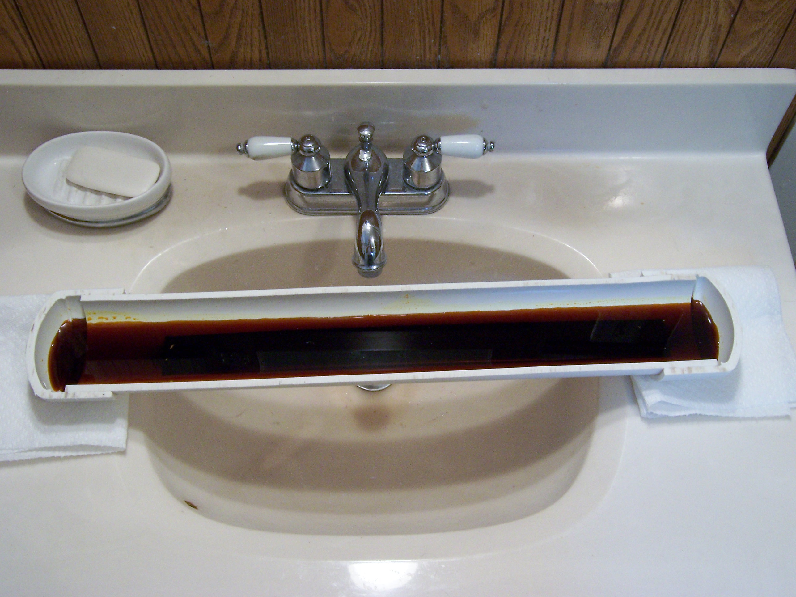
I set the tank over the bathroom sink with the ends on paper towels, in case my PVC glue joints weren’t watertight. Good thing, too, since they weren’t. By the end of the etch, one of the paper towels was stained, and I was particularly glad I’d used it.

Lesson: Use lots and lots of PVC cement to get watertight joints for odd configurations and applications.

At first, the etchant appeared to be removing quite a bit of copper, as evidenced by its increasing opacity. Half an hour in, though, not much was happening, even though I dropped by every few minutes to agitate the tank.

After a while, I got the bright idea to heat the etchant with my heat gun, and the etching really took off at that point, proceeding at a nearly visible pace.

Lesson: Heat the etchant to at least 100°F.

Once all the unwanted copper was etched away, I used a plastic fork to remove the board from the tank and rinsed it under lots of running water. Then I went to the kitchen sink to filter the used etchant into an empty plastic bottle for later reuse.

Lesson: Coffee filters pass about 1/4 cup of liquid etchant before becoming strangely impermeable.

Lesson: Impermeable coffee filters do not make particularly good funnels.

Lesson: Poor funnels tend to spill liquid over the edge into the white porcelain sink.

Lesson: Poor funnels tend to slip down inside the plastic bottle.

Lesson: The nooks at each end of capped PVC hold quite a bit of etchant that spills all over when you’re trying to pour it out.

Lesson: Start the etchant recovery process a couple of hours before your wife comes home so you have plenty of time to scrub the sink.
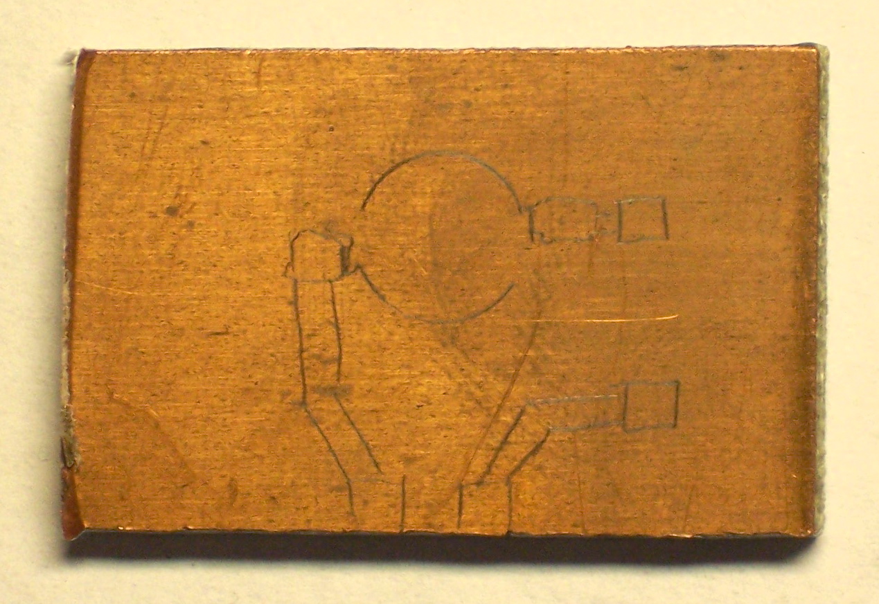
Results

Etched, cleaned PCB

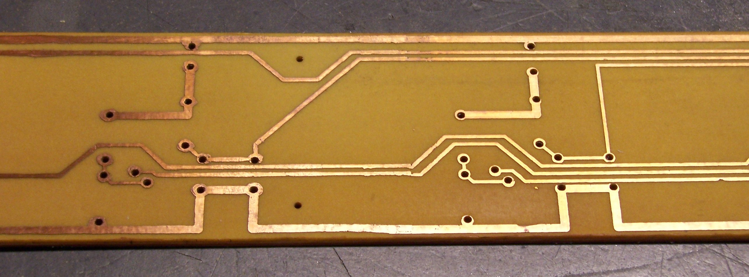
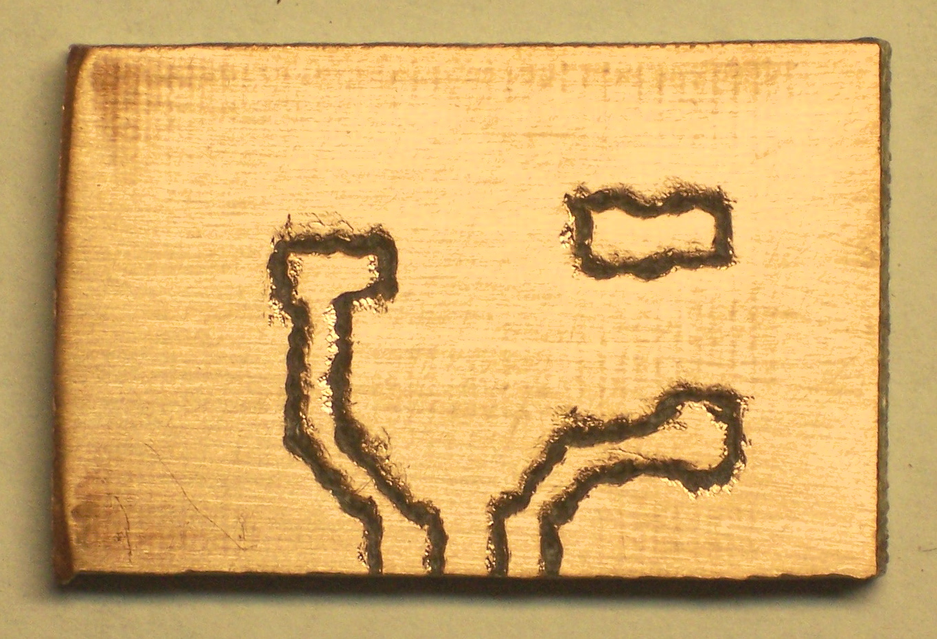
After cleaning the toner off the board with acetone, the traces really look nice. They have reasonably crisp edges and not too bad dropouts. This ended up being one of the nicer boards I’ve made by home etching.

Lesson: Try plain-paper toner transfer next time, using the paper towel pad trick.

PCB Layout and CNC Drilling Problems (and Solutions)

Monday, August 6th, 2007

I recently finished the prototype of my latest project (to be described in an upcoming post), and I made a lot of mistakes in PC board layout and construction. Like the SparkFun gallery of prototypes, I thought it was worth describing my problems and their solutions, to help myself and others avoid them in the future.

I’m doing that in two forms: a couple of detailed blog posts, and a new page with a summary version of the solutions. In the blog form, I’ll describe the problems in the order I encountered them; on the tips page, I’ll list the solutions in the order they’d be used when doing it right the first time.

Fitting the Case

The project I’m building is a control device for my stereo system, so I wanted to build it in a rackmount case. Rackmount project boxes seem to be inordinately expensive ($40+); so for the prototype, I salvaged a piece of dead network equipment (rackmount 12-channel 10M fiber-to-copper media converter), ditched the guts, and kept the case. The power supply was on a separate board and turned out to be 5V, so I left it in place to drive my circuit.

Rackmount fiber to copper media converter

Empty rackmount case with power supply

I needed pushbuttons and indicator LEDS on the front panel, so I planned my PCB to mount behind and parallel to the front of the enclosure. I measured the outside of the case and subtracted a generous .1″ from each edge to account for the thickness of the metal and to provide clearance around the edges of the PCB.

For the prototype, I decided to use the existing holes in the front panel for my LEDs and pushbuttons. I measured their approximate distances from the lower left corner and placed the components in the PCB layout program accordingly.

First mistake: When I measured for the size of the PCB, I didn’t look closely enough at the case. Where the top cover fits into the front edge of the case, there’s an extra lip underneath. I made the first board layout too tall to fit.

Lesson: Don’t make assumptions about the fit of the case. Inspect and measure where the PCB will actually fit.

Fortunately, before making a board, I printed the silkscreen layer and board outline from the layout software (FreePCB), cut and taped the pieces together, and held it inside the case to test the fit. I realized my error at that point, and correcting it was a (relatively) simple matter of changing the board outline and moving components and traces. I also tweaked the positions of the LEDs and pushbuttons for a better fit with the front-panel holes.

Auto Power Sequencer, top silk screen layer

Lesson: Print the board design on paper to test-fit into the enclosure before making a real board.

Challenges of a Single-Sided Board

I could have designed most of the circuitry using 7400-series digital logic, but some of the override functions I wanted to provide on the front panel would have got tricky, so I used a PIC microcontroller running the LogoChip language.

In order to perform firmware updates, I needed to include a serial port, but I didn’t really want to clutter the back panel with something that would be used so infrequently. For my own use, I like connecting with what I affectionately call a “Cisco blue cable,” the DB-9 to RJ-45 serial cable that ships with every piece of Cisco equipment (so I have a carton full of them). That meant putting an RJ-45 jack inside the case, and the problem was where to put the jack.

LogoChip in Altoids tin

Normally a jack would mount on the component side of the PC board, like the one up against the battery in my Curiously Strong LogoChip case, but here the component side was going to be pressed up against the inside of the front panel. Not only would that make the jack inaccessible (buried between the PCB and the front panel), but the jack was taller than the mounting hardware I wanted to use, and would have pushed the board too far back from the panel.

On a double-sided PC board, I could have mounted the jack on the “back” side and soldered it from the top. On my single-sided board, though, I’d have no way to solder it to the back-side traces — the jack itself would occupy the same space the soldering iron needed to.

Auto Power Sequencer, serial board

I decided to settle for making a very small daughterboard, just big enough for the jack and supporting components, to mount to a spare post in the bottom of the case. I wasn’t wild about the idea, but at least it’d get me by. In fact, I ended up scrapping the serial board idea and hooking up a temporary jack, for reasons I’ll describe later.

Lesson: Plan ahead for bulky components.

Drill Bits

Once I (thought I) had the board design finalized, I generated an Excellon drill file to take to Joel’s house and drill on his CNC machine. Because his machine has only about 12″ of travel and I needed to drill a 16.8″ panel, I needed to split the holes into two sections, so I could rotate the board halfway through and resume drilling from the other end.

To do this, I picked a spot to divide the board where I had a relatively long run of traces with no holes nearby. That way, inevitable alignment problems could be corrected by slanting the traces from both sides to meet in the middle.

I wrote a set of scripts for selecting, rotating, translating, and mirroring hole data in Excellon drill files. (I’ll post these after I clean them up a bit.) I also wrote a script to remove Excellon tags that Joel’s DanCAM software doesn’t recognize. (I had earlier created a drill export specification to generate DanCAM from EAGLE, but I was using FreePCB due to the larger board size.) I wrote up a nice Makefile to control the whole process, so I could export new drill files and just run make to get the new copies for Joel’s machine.

I cut a strip off my giant PC board from Slim, cut a couple of sections to length, and went over to Joel’s to start drilling. I decided to drill the boards copper-side-up, so I’d have less tear-out to sand off afterward.

PCB board with drilled holes

Lesson: Drill with the copper side up. It leaves perfectly clean holes that don’t need sanding.

I drilled the first board, and half of the third board, as a top-to-bottom mirror image of the correct hole placement. I drove back and forth across town to get more boards way too many times.

Lesson: Check drill file mirroring very carefully, to make sure it matches the placement of the board on the drill table.

I also ended up breaking something like four bits, mainly due to operator error. In the CAM software, you enter the heights of the Z axis with the drill bit up (out of the board) and down (drilled into the board). At one point, I miskeyed the up position lower than the down position, causing the machine to move the table with the bit lowered into the board. Snap. I always do a dry run before letting it drill the whole board, but it had already dived into the table before I could abort.

The machine was also drilling fairly aggressively for the size of bit I was using, resulting in the breaking of another bit. I slowed it down and didn’t break any more after that (I think).

Lesson: Be aware of CNC machining parameters, particularly those relating to position and speed.

But I didn’t start out with very many small drill bits, and each time I broke the smallest remaining one, the holes I was drilling got larger and larger. By the time I got the board finished with all the holes in the right place, I was using a 39-mil drill bit, which was way larger than I wanted — way larger than my component leads.

drill bit

Lesson: Stock up on appropriately-sized drill bits.

I’ve since placed an order with Drill Bit City for a couple of 25-packs of 5 each even sizes #72 – #64.

Drill Path

The hole list in the Excellon drill file isn’t in any particular physical order — the hole order probably has to do with the order the parts were imported into FreePCB from the partlist. DanCAM has an optimizing stage to reorder them into a more optimal path for the slow machine to travel, but I’ve noticed in the past that its idea of optimal seemed really strange and . . . suboptimal.

This time, I caught on to what was happening. DanCAM (at least the way we’re using it) doesn’t support changing drill bits to drill different-sized holes, so I drill all the holes with the same size bit. But internally, it’s still paying attention to the drill size, and optimizing each different bit’s path as a separate pass across the board, resulting in much unneeded movement when drilling with a single bit.

I updated my FreePCB Excellon to DanCAM conversion script to reduce the drill rack to a single size bit, and the next optimization and drilling operation went much faster than before — so much so that it felt like a qualitative rather than merely quantitative difference in drilling speed.

Lesson: If you’re drilling all the holes with the same size bit, make sure the machine knows that.

Having optimized the drill path so much better than before, I noticed that the machine was occasionally drilling the same hole more than once. I knew immediately why that was: Due to a quirk in the way FreePCB routes traces, there were numerous places on my board that I had multiple logical vias at the same physical location.

I wrote a very simple drill-uniq script to remove duplicate holes:

my %seen;

while (<>) {
    next if /^X/ && $seen{$_}++;

    print;
}

And the drilling operation got faster yet.

Lesson: Eliminate duplicate holes from the drill file, if the CNC machine isn’t smart enough to do it for you.

CNC Stepper Speed

My PC board production sequence is to drill the holes with the CNC machine, then print and iron on a toner transfer, then etch away the visible copper with ferric chloride. For the iron-on process to work, the predrilled holes need to align exactly with the printed copper trace pattern. I’ve noted in the past that they generally don’t align across the entire length or width of the board, and attributed that to inaccuracies in the paper feed rate of my laser printer.

This time, while I was waiting for one of several iterations of board to be drilled (due to my continuing errors), I checked the registration of the previous iteration and found it to be so bad that I got a ruler to find out exactly where the error was. It turns out that the answer was both — the drill and toner spacing were both wrong. Holding two iterations of drilled PCB up to the light revealed that the drill wasn’t even consistent from one pass to the next.

Since it’s a CNC drill, the only way that should be possible is if the steppers are skipping steps. If you push a stepper motor too fast, it skips (lags) a little bit, and stays out of sync until the next time you send it to the home position to check where it is. DanCAM’s setup process includes tests to make sure the motors are staying synchronized, but it’s pretty hard to tell if they’re losing only a few steps.

I went through the motor speed calibration section again, which boils down to running the motors faster and faster until they’re obviously losing steps, then backing off the speed until they seem stable again. I backed the speed off further than before, and on the next drill pass got all the holes as close to where they belonged as I was able to measure (except three that just randomly went a little bit off — still don’t know why, but I don’t think it was lost steps).

Lesson: Make sure the feed rates are within the steppers’ and drivers’ capacity.

At this point, I finally had a board that fit into my enclosure, with all the holes drilled (pretty much) where I wanted them. And a lot of things to remember to do better the next time.

Current Project Prototype Almost Done

Thursday, July 12th, 2007

FreePCB

Board layout is done, board is cut to size, drill files are converted to DanCAM format to drill at Joel’s house. I’ll print and iron on the etch resist after drilling. I’m going to try ironing on top-side “silk screen” like Cort’s been doing.

I drew the schematic in free EAGLE, but the board was too big to layout, so exported the netlist and imported to FreePCB. Substantially updated my eagle2pads netlist conversion utility, which I’ll be re-posting soon.

The FreePCB layout is so pretty, I just had to post it tonight.

Topics to cover after the board is made:

  • eagle2pads netlist conversion script updates
  • drill file selection and manipulation scripts and Makefile
  • custom etching tank
  • kits

Green Lines in My LCD Projector

Thursday, June 28th, 2007

I recently bought an ancient Sony “LCD Data Projector VPL-351Q” (video projector) on eBay for a reasonably modest price, without realizing just how ancient (and huge) it was. Fortunately, I was shopping geographically and was able to pick it up in person; it would have cost me a fortune to ship.

I’m interested in setting up a projector in the family room for watching movies, and this was a very affordable way to experiment before committing to an expensive course of action.

Sony LCD Data Projector VPL-351Q

That’s my 19″ stereo cabinet this thing is sitting on, with candlesticks elevating the front feet. It’s immense.

Old Lamp (Bulb)

Each time I power up the projector, it tells me that its lamp is old and needs to be replaced soon, which is no great surprise. (The onset of a lamp replacement warning seems to be a pretty strong motivator to retire projectors that are getting old anyway.) Of course, the few vendors I can find selling replacement lamps want $500 and up for them — a healthy order of magnitude more than I paid for the projector. Ha ha. This lamp is a bit dim, but not $500 dim.

I’m very curious how the projector knows the lamp is old — by counting hours of use (with a timer that I could reset?), or by monitoring lamp current. I’m also intrigued by the idea of rebuilding the lamp using something else — an automotive halogen bulb, perhaps. I assume I’d need to reuse the same reflector, and I think I might be able to manage it.

I’d also have to rig a different power supply for the replacement bulb — the original appears to run on 70V. The real problem would be if the projector monitors the bulb voltage or current (that I was no longer using) and shuts down if it seems improper. I’m not sure I’d be willing to go to the effort to rework or disable such a circuit.

Green Lines

Worse than the brightness, though, is a pair of green lines across the screen, just below the middle of the display. When I got it home and discovered them, I popped the case to have a look and found that the projector has a beam splitter, three monochrome LCD screens with color gels, and a beam . . . uh . . . unsplitter. So it’s plausible that the problem is isolated to the green LCD, and perhaps is nothing more than something is wrong with a row control line.

Image from my video projector with green lines

The black line, BTW, is a halogen torchiere — I’m temporarily projecting this onto the wall behind the couch. We’ll rearrange the furniture if it works out.

Inside the case, each LCD has two flex-PCB cables, presumably for row and column select. If the silk-screened labels are to be believed, the connectors in the upper center and right of the picture control the blue LCD, the lower center and left control green, and the one on the left plus the one disappearing off the upper left control red.

Sony VPL-351Q LCD control PCB

LCDs with which I’m familiar are clear when idle, and opaque when active. (Think of an LCD calculator or monochrome PDA — they’re grey when they’re off, not black.) If that’s how these LCDs work, then the bright green lines are rows that are letting green light through all the time — rows that are transparent all the time — rows that are never getting activated. Maybe I just had a bad connection on a pin or two.

(The connectors don’t have nearly as many pins as the horizontal and vertical resolution of the LCD, so my hypothesis isn’t perfect. A one-to-one match between control lines and rows would make a pretty compelling case. But even with row multiplexing or addressing, a single address line could still impact only one or two lines. Mmmmm . . . okay, not really; at least not two that close together. But bear with me.)

So the first thing I did was pull the cables for the green LCD, clean their contacts, and reassemble. Alas, no change.

Cold Solder?

Still chasing the notion of a bad connection, I wondered whether one of the ribbon sockets might have a bad solder joint. Logically it should be the green row controller; and since the LCD has lower vertical resolution than horizontal, that means it should be the smaller of the two green connectors — the one in the lower left.

Tonight I put the SMT tip on my soldering iron and went to reheat the solder job on the green connectors — on both green connectors, for good measure. I did reheat them — I made some nice solder bridges, and I think lifted a trace or two. When I tested the projector again, I had every seventh blue column missing (I had absent-mindedly touched up the wider blue connector also — so wide == columns), and some other strange artifacts.

Not yet deterred, I reheated the solder joints again. This time, though, I used the heat gun to do a more consistent job. I was concerned that the sockets were plastic and would melt before the solder reflowed; but I kept a close eye on them, and although they got a bit darker, they didn’t melt a bit. I knew I got the solder to reflow because the SMT slide switch actually tipped over sideways from the airflow at one point, then popped itself back up when I backed away.

The heat gun was the right approach and surface tension is my friend, because that treatment fixed the ills I had just caused. The projector is now back to two horizontal green lines.

What Next?

I’m curious how the ribbon cables attach to the LCDs. It still seems plausible that I have a bad connection somewhere, and perhaps that bad connection is at the green LCD itself. LCD elements that I’ve played with don’t have wire connections — everything on the glass is next to invisible, as if it’s painted on with disappearing ink. Connections are made by pressing metal or anisotropic rubber contacts against the traces on the glass — maybe one of those connections needs cleaning?

I’m willing to dig in and examine the LCDs, but I’m leery of unmounting them. They’re obviously positioned very precisely to get the three screens’ pixels to align on the output, and I haven’t looked closely enough yet to see how that alignment is done. I’ll want to be sure that I can get the screens realigned properly before I consider unmounting one to examine its connectors.

If the problem isn’t the green screen itself, then likely a driver chip is bad, or has a bad connection. I’ll get there eventually.

ResQPOD Circulatory Enhancer Circuit

Saturday, June 23rd, 2007

Back in May, I got this email from my friend J who works ER:

http://www.advancedcirculatory.com/CET/resqproduct.htm

I was at work last night and we had a code come in by ambulance. The Newton fire dept. now uses these when they code somebody. I saw that it had a circuit board and some LED’s and thought that you might be interested. It has been used but it I cleaned it up. Let me know if this is something that you want to take a look at.

“Code” is code blue, no respiration and no pulse. So J saved me a gizmo from a dead person, and “cleaned it up.” This is interesting. Wonder what it could be. I read the manufacturer’s web page and it doesn’t really enlighten me as to what kind of electronics are inside it.

I visit a few days later, and the gizmo looks like this:

ResQPOD

There’s a hole down the middle and a switch on the side. Turn on the switch and two red LEDs flash every six seconds. You plug the bottom end into a breathing mask and the top end into the CPR squeeze bag, and the lights tell you how often to squeeze for respiration for optimal (two-person) CPR timing.

A little bit of prying gets the case open, and the board pops right out.

ResQPOD PCB

There’s not much to the circuit — the eight-pin chip is obviously what makes it work. My first thought is that it’s going to be a 555 timer, but it’s labelled “MBAC ZC5.” Google gets me nothing useful to identify the chip, so I draw out a copy of the PCB traces to see whether I can get anything out of the pinouts.

For my first pass, I place the components on the schematic corresponding with their physical placement on the board. (I actually did this on paper; when I translated to EAGLE, I didn’t have a library component for the mystery part, so I used a connector that had the pins numbered wrong. Heed the green numbers I added, not the grey ones.)

Schematic diagram of PCB in ResQPOD Circulatory Enhancer, PCB order

Then I slide things around based on a logical placement.

Schematic diagram of PCB in ResQPOD Circulatory Enhancer, logical order

And this is starting to look awfully familiar — it is indeed the same pinout as a 555 in the astable multivibrator configuration, which makes perfect sense. In fact, the 555 circuit should have a connection from pin 2 (TRIGGER) to pin 6 (THRESHOLD) that I haven’t drawn — and when I look closely, I can see that it’s hidden underneath the chip.

So now I have a tiny SMT 555, a couple of red SMT LEDs, and a handful of SMT passives, plus a cell that’ll probably drive this thing for a long time. Cool.

Fire Alarm Dialer

Saturday, April 28th, 2007

What shall I do with this?

Fire alarm dialer box, front

You know your reputation as a salvager is increasing when the campus fire chief walks into your office and says, “I hear you might be interested in this.”

Yes. Yes I am.

Fire alarm dialer box, open

It’s a Microtel automatic dialer, built to watch a variety of analog and digital inputs, dial telephone numbers in response to alarm conditions, and play recorded and/or synthesized messages. It was installed under the floor of our data center, and apparently at some point its power was disconnected. After the backup gel battery drained, the voice card lost its mind. It’s old enough that they decided to replace the whole unit rather than the voice card.

Fire alarm dialer box, interior

The upper row is the system bus, containing the power supply, the CPU card, a voice memory card, and a telephone interface card. I’m not sure yet what the other card is. The lower row is the I/O bus, with two digital input cards.

What to Do?

I think it’s pretty cool. It’s a really nice enclosure. I love the LCD on the front panel, which looks like it has a parallel interface that should be easy to hack. The cards are intriguing, particularly if one of the chips is a voice synthesizer. The power supply offers 5V and 12V, and already knows how to charge a gel cell and cut over to it when power fails.

But I’m surprised at the enthusiastic response I’m getting from non-electronics-geeks. The normally reserved Garrett positively gushed over it, and today my friend Jonathan (ER nurse and fix-it guy) expressed how awesome it was, and how many cool things you could do with it.

All right, then, you tell me. What should I do with it? Enclosure, components, or the works?

PC Board Vise

Sunday, April 22nd, 2007

I’d heard that PC board vises were the cat’s meow for stuffing and soldering boards, and I’ve seen them used in a couple of “how to solder” videos. So when my friend Cort was putting together a big parts order recently, I had him add on a vise for me. Here it is.

PCB vise

It came in pieces: the base, the spindle, the bar, the clamps, and all the knobs. Pretty easy to put together, but I had one little problem:

PCB vise with misaligned jaws

The jaws didn’t line up. Like, so bad there’s no way I could make a decent PCB stay put.

The square holes to fit over the bar had casting flash left in them; and the bar itself is rhomboid instead of square, so it doesn’t fit snugly into the jaws’ (allegedly-)square corners. It was even possible to wiggle the jaws and make them misalign in the other direction, but not to get them to stay aligned.

PCB vise with realigned jaws

So earlier this weekend, I sat down with a square file and got all the flash out. I also found which way the clamps fit best on the bar and reoriented them to that position. Now they’re stable and pretty well aligned.

PCB vise holding my stepper control board

I got to use it for soldering some of the last components of my stepper control board. The vise’s spindle has a joint that folds 90° forward or back, so I assembled it to have the jaws pointing straight up when the spindle is straight. I fold it forward to do top-side work, and then fold it back up and over backward to do bottom-side working. Verra nice!

Nightmare Workbench

Sunday, April 22nd, 2007

My workbench

I think it might be time for me to tidy a bit.

Testing the Luxeon I LED

Friday, April 13th, 2007

I have some ideas for things I’d like to do with really bright LEDs, and Philips has the brightest that are readily available to hobbyists right now. They’re brand-named Luxeon, and they’re manufactured and marketed by a wholly-owned company named Lumileds.

A typical 5mm LED can pass 15-20mA of current. Lumileds’ first product to market was the Luxeon I, which (when properly heatsinked) can pass 350mA of current; their more recent LEDs can handle even more. An LED’s power-handling capacity is mainly limited by heat, and Lumileds has found a way to bond the LED die to a heatsink that extends out the base of the package, for further external heatsinking. This allows their LEDs to pass vastly more current without burning out.

Luxeon I Emitter LED

A while back, I found a good price on some Luxeon I emitters (just the LED; Luxeons are also available premounted on a star-shaped base) on eBay and bought a small batch to experiment with. Because I knew that external heatsinking was required to drive them at anywhere near their capacity, I set them aside until I’d have an opportunity to build a test PCB.

Design Considerations

Two documents from Lumileds proved particularly helpful:

The LED’s heatsink (“slug”) is not electrically neutral, and must not be connected to either the anode or cathode. It must not be soldered, and should be joined to a heatsink with thermal grease or epoxy. So a carrier PCB should have a large copper plane for the slug, and the electrical connections for the anode and cathode should interrupt the plane as little as possible.

The Thermal Design Guide goes on to say that standard PCB substrates don’t dissipate heat well enough for Luxeons, and aluminum metal-core PCBs are recommended. Each LED should ideally have 36 in2 of heatsink, and an LED with only 1 in2 of heatsink can be operated at room temperature but may reach up to 70°C.

Whatever. I have plain old PCB, and it’s going to have to be good enough to test with.

The Electrical Drive document recommends powering the LEDs with a constant-current source. LEDs are commonly powered with a series current-limiting resistor; but at the high operating current of Luxeon LEDs, a great deal of power is wasted (and converted to heat) in a series resistor. Constant-current drivers place a very low-valued “sense resistor” in series with the LED, then measure the voltage drop across the sense resistor to feed back and control the supplied power.

Whatever. I have a plain old resistor, and it’s going to have to be good enough to test with.

Resistor Selection

This was actually a pretty quick calculation, and I did it in my head because I don’t mind being a little sloppy with this test rig, but it’s good to run through the details anyway.

The Thermal Guide recommends no more than 100mA without good heatsinking, but I figured I’d shoot for 200mA (out of 350mA when properly heatsinked) and see what happened.

The voltage drop across the resistor (VR) is equal to the supply voltage (VS) minus the diode’s voltage drop (VD):

VR = VS – VD

With a 5V supply and approximately 3V drop across the diode, we get

VR = 5V – 3V = 2V

For a target current of 200mA:

R = VR / I
    = 2V / .2A = 10Ω

Then the power-handling capacity of the resistor needs to be:

P = I V
    = .2A * 2V = .4W

So I pulled a 10Ω half-watt resistor out of my parts bin and was ready to go.

Constructing a Test PCB

I didn’t feel like etching a board, and I don’t have a milling machine built yet, so I went the scabby route and hand-milled a board with a rotary tool.

First I traced the LED’s outline onto a scrap of PCB (a little over 1 inch square), marked pads to surface-solder a resistor and power connectors, and drew in connecting traces.

Luxeon prototype board with components traced

I outlined the paths I needed to cut to isolate the traces from each other,

Luxeon prototype board marked for milling

then chucked a milling bit into a rotary tool and got to work.

Luxeon prototype board, hand-milled trace isolation

The milling bit has burred edges and was really intended for cutting PCB edges rather than milling trace isolation, so it did a pretty nasty job.

Luxeon prototype board, milled and polished

It cleaned up okay with some 600-grit sandpaper, though. I hadn’t bothered cleaning the board at all before I started, since I knew I’d want to sand to knock down the burrs after milling anyway.

Since I couldn’t find my old tube of thermal grease and my wife was running into town anyway, I asked her to pick some up for me. While I waited, I couldn’t resist soldering on the, uh, resistor.

Luxeon prototype board, resistor soldered

When she got back, I dabbed a little bit of thermal compound onto the LED’s slug, jammed it onto the board, and soldered it down. Its leads are pretty flexible, so I tack-soldered one, then pressed down on the LED’s lens to make good contact between the slug and the board while soldering the second lead.

Completed Luxeon prototype board, top view

I cut a couple of one-pin sockets, soldered them to the board, and was ready to roll.

Ow. It’s Bright.

I wired the test board up to my bench power supply and eased up the voltage control. Around 3V the LED sprang to light: BAM, and it was on. From there to 5V, the brightness increased; and I can get even a little more by going up to 6V before I get nervous and back it off.

The LED is extremely bright, for an LED. I couldn’t get a good picture of it without my camera washing out–this is sitting on bright white typing paper directly under my desk lamp. Imagine the whole thing that much brighter.

Lighted Luxeon LED on prototype board

Also, the Luxeon has a great viewing angle. They advertise it as 120°, and I can definitely believe that.

Lighted Luxeon LED on prototype board

Turning out the room lights made for a good demonstration but another misrepresentative photo:

Luxeon shining in the dark

It lit the part of the room around my desk well enough to see, although not nearly as brightly as I’d like. I think the Luxeon I LEDs are rated at 40 Lumens, and a 100W incandescent is around 1600 Lumens. We have a ways to go before we’re lighting our houses with LEDs.

The batch I got was called cool white, and it had a very blue cast to it. I’m interested in getting my hands on some warm white next, and maybe some amber.

For now, I’m pleased with the results of the test. I can test different drive methods now, including replacing the 10Ω resistor with a smaller sense resistor if I choose. I have a visual reference of the apparent brightness, and I know I don’t like the color temperature of this particular bulb. And I measured the thermal temperature while it was running–the PCB right around the LED got up to 86°F after a few minutes while the rest of it stayed cool, which is good to know.

I just remembered I have a 1400mA Luxeon III that the eBay seller threw in with the Luxeon I’s I bought . . .

LED Gloves

Sunday, April 1st, 2007

Background

Steve Wilson is a graduate student involved in WSU’s CRATEL (Center for Research in Art, Technology, Education, and Learning) program, and his video synthesizer was sponsored for further development in last year’s BETA (Bridging Entrepreneurship, Technology, and the Arts) competition.

One of Steve’s challenges for his video synth, and an interest in general, is creating expressive interfaces to electronic instruments. He describes it in a post to the Technology: Art and Sound by Design class mailing list. Basically, it comes down to the idea that acoustic instruments offer an immense amount of control over the sound that comes out through physical manipulation, and electronic instruments tend to offer much less control, and through mechanisms mainly like knobs and sliders.

While brainstorming with Steve about his synth, several of us came up with the idea of an interface like a plasma globe, which you control by moving your fingers over the surface. A cheap videocamera inside could watch what was happening and control the action.

Apparently a group of engineering students have been working on the globe subproject for six months without much progress to report. Although their difficulties seem to be mainly lack of organization and lack of time, others of us had talked about how clear an image might be obtainable on the camera with the globe lighted from the inside or outside.

Finally it occurred to me (while driving home from work) that gloves with LEDs on the fingertips would make lighted spots that should be very easy to see from the inside of the globe. Different colored LEDs on different fingers would allow the driver software to identify the different fingers; and pressing the LED against a translucent surface will produce a sharper point than holding it further away, so it might even be possible to determine approximately how near a fingertip is to the globe’s surface. And if made properly, the glove could be worn without impeding other use of the hand–just adding lights for the globe.

Time to prototype.

Gloves

I was hoping to find a cheap lycra glove to make something like the original Dataglove. (Yes, I have a Dataglove system. No, you can’t play with it.) What I found instead was certainly cheap, but knit cotton instead of lycra. Heck, for 96¢, it was good enough.

When I put the gloves on, I could feel that they’d been assembled somewhat sloppily. Inside-out, it was easy to see that there was a lot of extra fabric inside the fingers outside the stitching:

Fingers need to be trimmed

So I trimmed it a little closer and more evenly around the fingertips, for better fit and comfort.

Fingers trimmed

LEDs

I wanted to use surface-mount technology (SMT) LEDs, so they’d fit flat against the glove surface. The ones in my stockpile are out of broken digital office phones, used to light up beside the line appearance and feature buttons.

I wanted to be sure I knew the polarity before I started attaching things and soldering them together, so I tested first with my meter. The LEDs actually lit with the small amount of current it supplies, which was kind of cool. Curiously, the green LEDs have the anode on the end with the cut corner, and the red LEDs have the cathode on the end with the cut corner. On each LED that I identified, I marked the anode end with the color of the LED. (The ones on this sheet are tinted to indicate their color, but the ones I’d already removed weren’t.)

The phone flex-PCB has a 300Ω resistor in series with each LED, so I tried out a couple there on the strip. Nice and bright.

Testing an SMT LED

Soldering the LEDs

My plan was to solder wire the LEDs, then sew the wire through the glove to the back side, where I wanted to attach a battery holder. I got out some fine wire, scraped off the enamel insulation, wrapped it around the fly leads on the LED, and soldered it up.

Soldering the SMT LEDs

Sewing

After I had both wires soldered to the LED, I threaded one at a time through a needle, held the LED about where I thought I wanted it on the fingertip, and started sewing. The goal was to get the wire from the tip of the finger to the back of the hand without leaving any large loops that might snag on anything, and without reducing the stretchiness of the glove. The latter factor called for a zig-zag stitch, which with a single thread looks like a running pattern of slash marks.

LED on second finger

Once I got the wire stitched around to the back side, I followed along the back of the finger and then curved toward the center of the back of the hand.

Stitching from the back of the finger toward the battery

Glue for Protection

I needed something to protect the LEDs on the fingertips so they wouldn’t snag. When the wires were safely stitched around out of the way, I got out the hot glue gun, put on the glove, put a dot of molten glue over the LED, and pressed the glue into a perfectly-shaped dimple in a USB serial connecter that I lifted from the CRATEL lab. It soaked into the fabric a bit, adhered very well, and made a nice smooth bubble over the LED.

Glue bubble over LED

Well, mostly nice and smooth. Hot glue tends to stretch like pizza cheese, and I made a little boo-boo.

Battery Holder

For now, I settled on prototyping just two fingers, because I have only two colors of SMT LEDs, and because it seemed like enough for a proof of concept. I steered the appropriate wires onto the same paths and ran them up to where I wanted the battery holder.

Back-side stitching for two fingers

Then I clipped the wires short, scraped the ends, folded the glove over to get room to work, and wrapped the wires around the leads of a surface-mount coin-cell holder salvaged from a PC motherboard.

Soldering battery holder

I soldered them on, then folded the battery holder leads underneath so they wouldn’t poke through the glove and scratch up the hand. Laid back out, it looked like this.

Back of glove with battery holder attached

The Lights

I didn’t bother with a switch on the prototype–just pop in the coin cell and the LEDs come on. And because I’m using an old, small battery, I didn’t bother with current-limiting resistors–the internal resistance of the battery seems to be enough to limit the current to the LEDs.

Lighted fingers

Due to the idiosyncracies of my digital camera, the green LED on the index finger doesn’t look very green in this picture, but it really is. It’s a lot dimmer than the red LED, though; and I’m not sure why that is. Before going beyond a prototype, I’d want to pick current-limiting resistors to more closely calibrate the brightness of the different LEDs.

I don’t have a translucent globe to use, but I borrowed a hemispherical Tupperware bowl from my friend Lawrence’s daughters. (Don’t ask my why the girls have their own set of Tupperware–I really don’t know.) It works well enough to demonstrate the idea:

LED fingers through Tupperware

You can clearly see where the red LED is touching the bowl. Now all we need is a videocamera, some fancy software to track the lights, and an interface to a video synth. :-)

Seriously, all of those things are Steve’s domain. I just wanted to see whether I could throw together a working glove, and I think this’ll do.

Oh–and when you want to shut it off, you take out the battery and drop it into the thumb.