Archive for the ‘LED Clock’ Category

LED Clock: Escalating Resistor Dispute

Wednesday, July 12th, 2006

As I haven’t heard anything from Best Hong Kong in the week since my last email to them, I assume they’re not planning to get back to me. I just escalated my dispute to a claim, with this notation:

I picked this auction out of various LEDs offered for sale in part because it advertised my choice of free resistors; and I was very careful to follow the seller’s instructions during checkout to specify which resistors I wanted (which I notice they don’t deny).

I would really prefer to have the seller ship me the resistors I specified, completing the auction. However, as I can buy the same resistors (220-ohm 1/4 watt) through Digi-Key (a widely known mail-order catalog) for as low as $5.40 plus shipping, I guess I’d be willing to accept a $6 refund.

Since the error in sending the wrong resistors was made entirely by the seller, and if they’re really not willing to send me the right ones, I don’t see why I should be willing to accept a lesser refund than what it will cost me to replace the resistors from an alternate source. Any other outcome means that the seller’s error costs me money, which doesn’t seem appropriate.

PayPal’s system displayed this confirmation message:

A claim has been filed against this transaction. The seller’s deadline for responding to this claim is . The seller has the option to provide a full refund for the amount of the transaction, offer a full refund if the item is returned in its original condition, offer a partial refund in an amount you agree to, provide proof that a refund was already issued to you, or disagree with your claim. If the seller does not respond by the deadline, the claim will be decided in your favor. You may cancel this case at any time by clicking “Cancel” below.

LED Clock: Interfacing to the DS1302 RTC Chip

Friday, July 7th, 2006

It occurred to me that I haven’t posted the latest update on data interfacing to the Dallas/Maxim DS1302 real-time clock (RTC) chip; and then I searched and saw that I haven’t posted anything on it. I received the sample chips mid-June and started working with them after I had prototyped the A6276 LED driver and was waiting for my shipment of LEDs. Apparently once I received the LEDs, I was so excited by the bright blue glow that I forgot to get back to the timekeeping functions. :-)

“Auditioning” the 1302

I’m looking at two different timekeeping chips to use in the clock. The DS1340 looks like the better choice but is only available in surface-mount packages, so I’ll need to make a carrier before I can breadboard it to test; thus so far I’ve been testing the DS1302.

The 1302 tracks YY/MM/DD HH:MM:SS plus day of week and choice of 24-hour or AM/PM. It uses an external 32768Hz oscillator and has a VCC2 input to allow it to run on a lithium backup battery for up to 11 years in the absence of primary power. It doesn’t do daylight savings time, has century-unaware leap year support (but my clock will not still be in use in 2100), and requires you to set day of week manually rather than calculating it algorithmically. It’s not terribly sophisticated–but I don’t need terrible sophistication to get this job done.

It uses a “simple” three-wire interface for data communications:

Name Signal Use
CE clock enable? raise to begin transmission; lower to end communication
SCLK serial clock? cycle to transmit and receive data
I/O I/O data to and from clock chip

To write data to the 1302, raise CE, transmit the register address to the 1302 (setting the low bit to indicate a write operation, and clocking each bit), transmit the data (clocking each bit), and lower CE. To read data from the 1302, raise CE and transmit the register address (clearing the low bit, and clocking), continue clocking and read the received data, and lower CE.

But in the Real World . . .

I jumpered it to my Curiously Strong LogoChip and coded up an implementation of the protocol, but was getting totally random data back. The 1302 claims to support clock speeds down to DC (i.e. as slow as you want it to go), so I slowed it down to 1Hz and put the logic probe on it to see whether the bits it was sending matched the bytes I was outputting. After watching it send ultra-high-speed flurries of data back in response to the slow requests I was sending it, I realized it behaves much more predictably when I connect its ground pin to ground instead of leaving it floating. Oopsie.

Once I was actually communicating with the chip with a common voltage reference, I was able to read and display its seconds register. I found that it changed once a second as expected; and I knew its output wouldn’t be a simple count from 0-59, because it uses binary-coded decimal (BCD), where each nybble is the binary coding for the corresponding decimal digit.

I was surprised, though, to see the values alternating high and low: 64, 192, 65, 192, 66, 194, 67, 195. This suggested a bit alignment problem–I wasn’t reading the right bit in the right position. I wrote a Perl script to translate the decimal values into binary with leading zeroes (to make the bits line up so I could scan visually for patterns) and fed it a complete 60-second cycle, with this result:

64  -  01000000
192  -  11000000
65  -  01000001
193  -  11000001
66  -  01000010
194  -  11000010
67  -  01000011
195  -  11000011
68  -  01000100
196  -  11000100
72  -  01001000
200  -  11001000
73  -  01001001
201  -  11001001
74  -  01001010
202  -  11001010
75  -  01001011
203  -  11001011
76  -  01001100
204  -  11001100
80  -  01010000
208  -  11010000
81  -  01010001
209  -  11010001
82  -  01010010
210  -  11010010
83  -  01010011
211  -  11010011
84  -  01010100
212  -  11010100
88  -  01011000
216  -  11011000
89  -  01011001
217  -  11011001
90  -  01011010
218  -  11011010
91  -  01011011
219  -  11011011
92  -  01011100

I needn’t have included the whole thing, because it’s obvious what’s happening. What I thought was the high bit was changing the most rapidly, so it must in fact be the low bit. Somehow the byte got rotated one bit to the right. It’s only fair to mention at this point that the chip will keep repeating its transmitted data as long as you keep clocking it; so a rotation like this simply means that I’m a clock cycle off, not that something utterly bizarre is happening.

I searched my code for an errant clock cycle between the address-write and the data-read, but couldn’t find anything amiss. As an ugly kludge to get it working, I changed the read routine to cycle the clock after reading the bit rather than before, and of course began to get the correct data. Then I reexamined the datasheet and found the slightest justification in their confusing language that this behavior is by design: the first bit from the DS1302 is transmitted on the falling edge of the same clock cycle whose rising edge carried the last bit of the address register. Ewwwww.

I’ve been trying to think of cleverer ways to adapt to the situation, but haven’t come up with any. Clocking after reading works for single-byte reads, and should work (I haven’t tried it yet) for multi-byte reads in burst mode. So I guess I’ll leave it that way.

Here are the first few entries of a correct seconds cycle, in all their glory:

128  -  1 | 000 | 0000
129  -  1 | 000 | 0001
130  -  1 | 000 | 0010
131  -  1 | 000 | 0011
132  -  1 | 000 | 0100
133  -  1 | 000 | 0101
134  -  1 | 000 | 0110
135  -  1 | 000 | 0111
136  -  1 | 000 | 1000
137  -  1 | 000 | 1001
144  -  1 | 001 | 0000
145  -  1 | 001 | 0001
146  -  1 | 001 | 0010
147  -  1 | 001 | 0011

The 1 in the high bit of the high nybble represents that the clock is halted (which it obviously isn’t; not sure what to make of that, unless maybe it’s a write-only register???), the next three bits represent the tens-of-seconds digit, and the lower four bits represent the seconds digit. So this short list here shows seconds 00 – 13.

Higher-Level Timekeeping Functions

In order to be able to interpret the data coming back while testing the read routines, I had already written some functions to parse the time data. I haven’t gone back to test all of them after getting the read working, and I have some cleaning up to do on them anyway. Now that I have a one-digit prototype display working, I think returning to the timekeeping is the next step. Hopefully I can soon integrate the two, so the demo display can show actual seconds information.

LED Clock: Resistor Dispute Continues

Wednesday, July 5th, 2006

Best Hong Kong:

We do preferred to send you $1 to close this dispute. The gift, which is not worth $1 and we did send you the 470ohm resistors already which is perfect for 12VDC power. if you want us to send the extra 220ohm, please close the dispute and we’ll do it.

Me:

I don’t know why you describe the resistors as a gift, because they were part of the auction listing, therefore part of the auction. And while they may be worth less than $1 to you, unfortunately it would cost me $6 to replace them from another source, so I don’t think it’s fair for you to describe their value as less than $1. Also, for what it’s worth, I’m not using 12V power, so the wrong resistors you sent don’t do me any good–that’s why I ordered 220-ohm resistors, which are what I need.

I’m trying to be reasonable and work with you to correct the mistake you made when you sent the wrong resistors, but I’m not willing to close the dispute until I receive the right ones. Again, if you do send the 220-ohm resistors, I will happily close the dispute as soon as I receive them.

LED Clock: Disputing Resistors

Tuesday, July 4th, 2006

Here’s Best Hong Kong’s response to the dispute I opened with PayPal about the resistors not being the value I requested:

We can do 2 options. we refund you $1. or close the dispute and we’ll send you again, 100pcs of 220ohm resistors. by air mail. if you want a trackable shipment, you will need to pay $2.30 for registered air mail charge. if you want the resistors, please close the dispute and then email ken@besthongkong.com your address & a copy of my msg here. we’ll then send the resistor out in our next shipment. Regards, Ken Besthongkong.com

My reply:

I definitely want the replacement 220-ohm resistors–that’s exactly what I’m asking for, so thank you for offering.

But PayPal specifically says I can’t close the dispute until I receive the resistors:

“Likewise, if the seller is going to send a replacement item, don’t close the dispute until you have received it.”

So please go ahead and send them. I understand the overseas shipping will take a little while, and that’s okay; also, I don’t think trackable shipping is necessary. As soon as I receive the resistors, I’ll immediately close the dispute and leave you positive feedback on eBay for correcting the mistake promptly and courteously.

And the entire PayPal “Dispute Resolution and Tips” policy I’m citing:

When should I close this dispute?

Wait until you are 100% satisfied that the dispute is fully resolved before closing the dispute. A closed dispute cannot be re-opened or escalated to a PayPal claim, so before you close your dispute you should ensure that your concerns have been fully addressed. For example, if the seller is going to provide a refund, make sure that the funds are in your account before closing the dispute. Likewise, if the seller is going to send a replacement item, don’t close the dispute until you have received it.

Remember, a dispute will automatically close 20 days after the date it was opened. You should escalate a dispute to a claim if you haven’t fully resolved the issue within 20 days.

LED Clock: It’s Blue. It’s Beautiful.

Tuesday, July 4th, 2006

Software

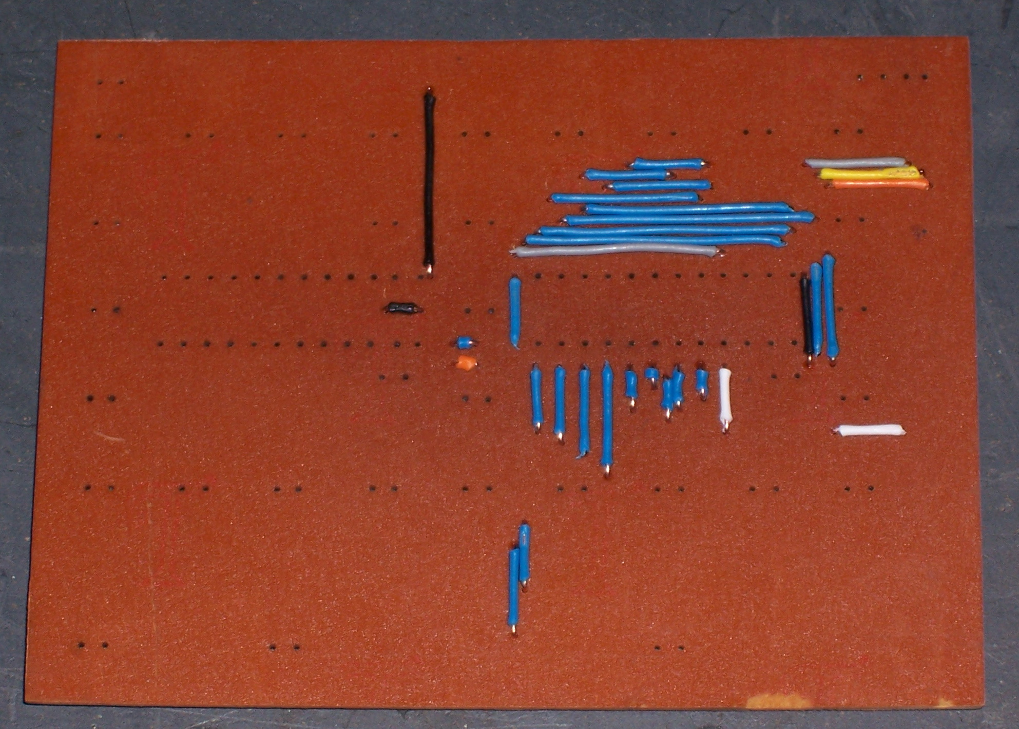
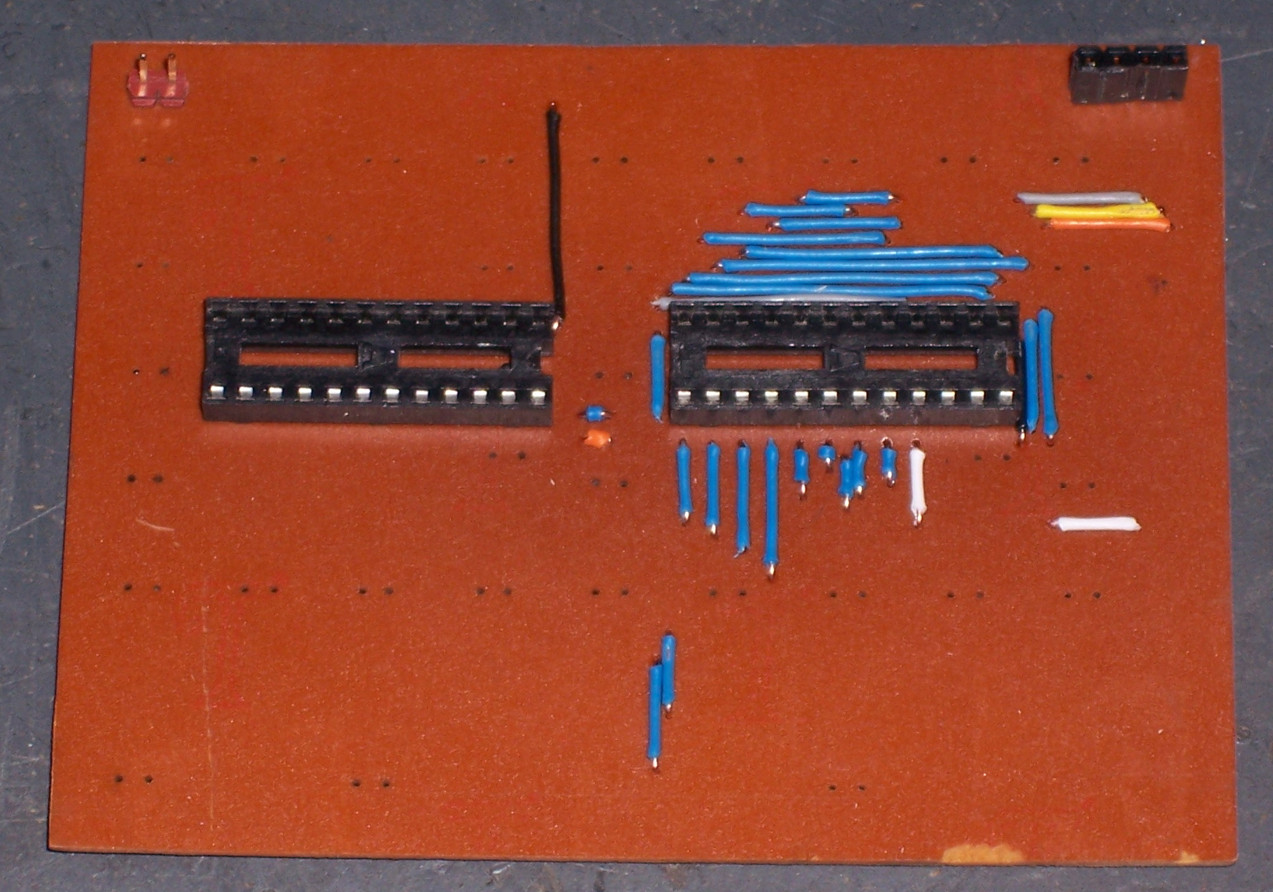
Even before I had installed all the LEDs in the prototype board, I couldn’t resist turning the thing on and lighting them up. I started by pushing a 1 and two 0s into the thing, to make it cycle like the lights around the edge of a marquee:

loop [ a6276-bit 1 a6276-latch wait 5 a6276-bit 0 a6276-latch wait 5 a6276-bit 0 a6276-latch wait 5 ]

That’s one lighted dot, half a second delay, one dark dot, half a second delay, another dark dot, and another half second. The effect is every third light marching around the loops in half-second steps. Then I finished assembling the board and wrote a routine to send a single dot around the loops:

to a6276-demo-onedot :delay
    a6276-off
    a6276-off

    loop [
        a6276-bit 1
        a6276-latch
        mwait :delay

        repeat 31 [
            a6276-bit 0
            a6276-latch
            mwait :delay
        ]
    ]
end

Of course, I started speeding it up so the dot was spinning around the loops instead of marching. I was pleased to see that it can run fast enough that the flickering of the dots disappears and the whole display just looks like it’s on but dim.

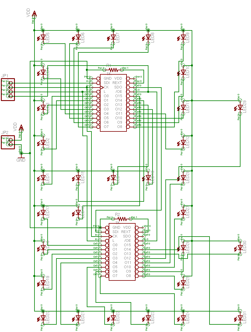
Next, I had to display a 2, since making the 2 look good has become the epitome of the whole project. I had already written code to pump 16 bits into one 6276, and LogoChip Logo uses 16-bit words, so I sent the pixel data two words at a time:

global [ a6276-temp-data ]
to a6276-shift16 :data
    seta6276-temp-data :data

    repeat 16 [
        ifelse (#1 and a6276-temp-data) [
            a6276-bit 1
        ] [
            a6276-bit 0
        ]
        seta6276-temp-data leftshift a6276-temp-data -1
    ]
end

to a6276-display-2
    a6276-shift-16 #0001011101111101
    a6276-shift-16 #0111111100000000
    a6276-latch
end

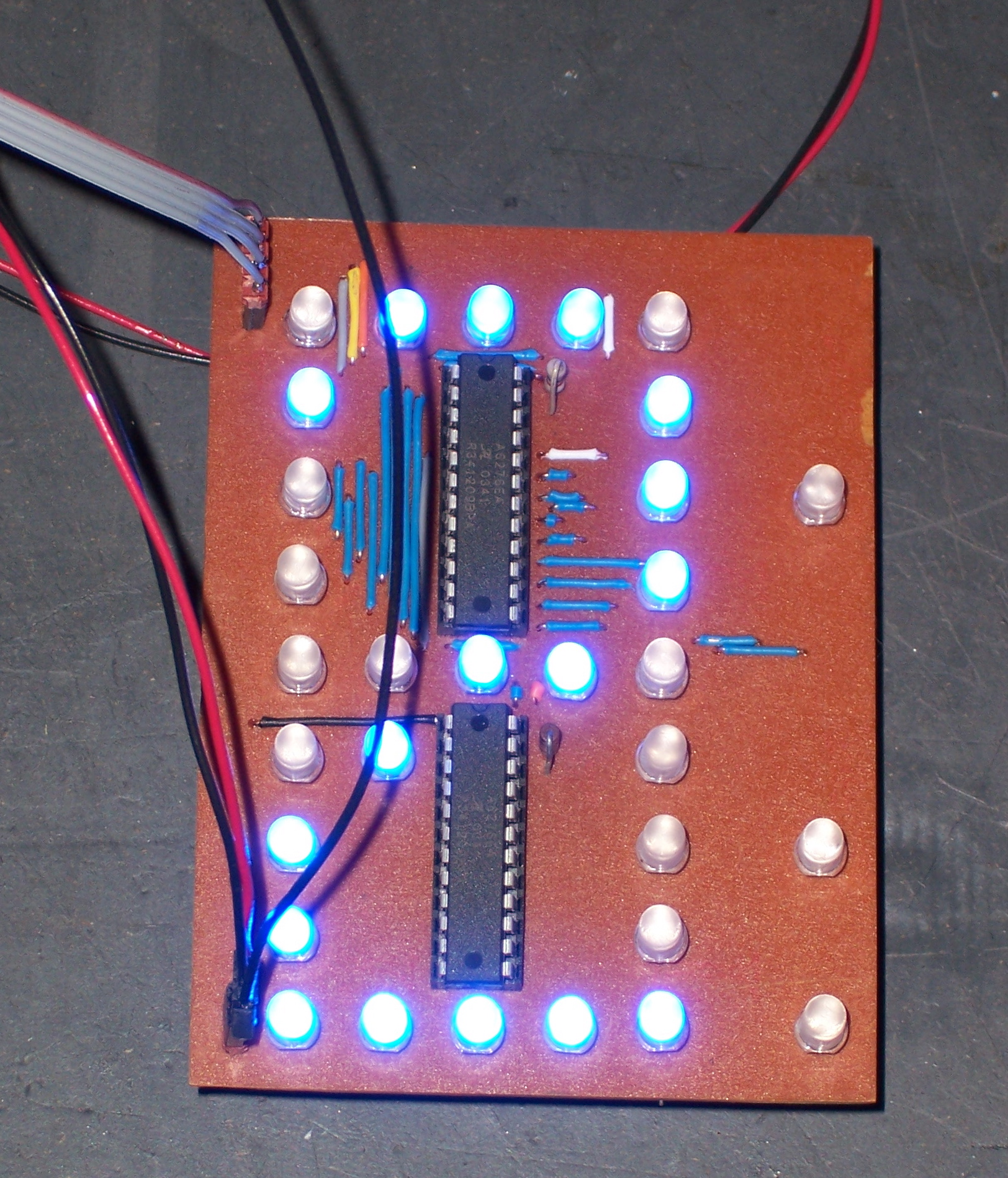
And here’s how it looks.

2

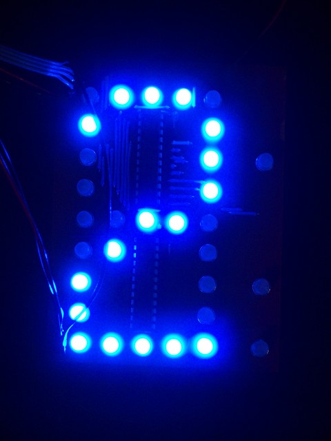
I followed that up by constructing the rest of the digits in separate subroutines, then adding parameters for whether to light the colon and the decimal point, then creating a loop to flash the colon on and off each second while counting the seconds on the display. Which leads into the next point . . .

Power Supply

I’m using my Curiously Strong LogoChip to control the display board, and it runs on a (rechargeable) 9V battery. I connected my bench power supply to the display itself, ’cause it draws a little more current; but all indications are that the LogoChip doesn’t use that much.

After getting the seconds-counter working, I left it running all evening while doing other things around the house. When I went back out to the utility later, it seemed like it was running slower, and comparing it to the second-hand on the kitchen wall clock showed that it definitely was.

At first, I wondered whether I had some kind of leak in my software loops, but then I thought of the battery running down, and that’s what it turned out to be. Even though I’m using an external 10MHz crystal on the LogoChip, it must use an internal oscillator for the Logo wait command; and that internal oscillator must be supply-voltage-sensitive.

So I powered my baby off for Saturday night, and Sunday afternoon wired it up to an old PC power supply. PC supplies tend to provide very well-regulated 5V with as many amps as you could hope to throw at a little circuit like this, and they can do it forever and ever without getting bored.

There’s just one catch–they need a minimum load to turn on. Because of the way switching power supplies use feedback to correct changes in output voltage, they have to have something drawing current, or they go into protection mode and shut down. Although the tiny current draw of my LogoChip was enough to drain a 9V battery after a few hours, it’s not enough to keep a PC power supply happy.

There are articles online about converting a PC power supply to use as a general-purpose bench power supply, and most of them have you stick a large resistor inside the case to draw current. The resistor gets really hot, of course, and wastes power if you do have enough external load to keep the power supply on; so you want to size the resistor to draw the minimum current required to activate the power supply.

I couldn’t find any good data on how much current is typically required to keep a PC switching supply active, but I found people talking about half an amp. Well, 5V / 10Ω = .5A, and 5V ⋅ .5A = 2.5W. Most of the power resistors in my parts bin are good for 5W or 10W, so I just had to find one with about the right value. The closest I could come was 15Ω, which would give a third of an amp, which might be close enough.

I was getting ready to wire it in when I had an even better idea (at least for the prototype bench), spurred by trying to figure out where to salvage a four-pin Molex connector to solder the resistor to. If you’re old enough, you may remember the days when PCs wouldn’t boot if you disconnected all of their hard drives, because they needed more of a load on their power supplies than the motherboards alone provided. (I know, now that CPUs draw more current than a toaster oven, that’s a little hard to imagine; but trust me, it happened.) So . . . if a hard drive was enough to load the power supply, maybe a hard drive would be enough to load the power supply.

Hard Drive as Dummy Load

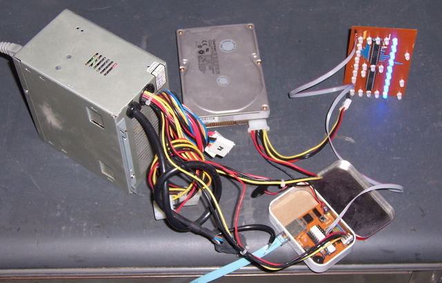
I call this “Best Use of Useless Hard Drives.” I grabbed a spare courtesy of my friend Matt at the office, and away she went! Even better, when I go a-salvagin’ for more power supplies, they’ll be out of ’386es that have like 100M drives on them. Perfect! I’m thinking of just attaching it to the side of the power supply with duct tape, so it’s always there for me. :-) No, seriously, I’ll stick a power resistor inside eventually, but this is working great for now.

The Result

I’ve had the single-digit seconds-counter running for about a day and a half, and it’s working just fine. It’s still using internal timing rather than an external timekeeper; so it’s not perfectly accurate, but it looks good. I put 1K resistors on the 6276es for control resistors, and the graph on the datasheet suggests that means the LEDs are running about 20mA, which is very conservative for what these are able to handle. My wife says it’s insanely bright, and actually turned it around to face the other direction so she could stand to be in the same room with it.

Did I mention that the picture above (of the 2 on the display) was taken with full daylight streaming in the side window? Same as on this video, of counting through the numbers.


LED Clock: Prototype Digit Assembly

Monday, July 3rd, 2006

Tinning the Board

The first step of assembly was tinning the board. I was going to be soldering a lot of jumpers to the top of the board, and the longer I had to hold the iron on each one, the further back the insulation would melt. Tinning the board (putting solder on all the pads) helps the solder flow almost instantly to each lead during component soldering.

I have a bag of Tinnit, which is a solution that’s supposed to tin the whole board for you. I’ve never opened it, though, because it has a relatively short shelf life once mixed with water, and I don’t make enough boards to be worth wasting a whole bag. I know, makes a lot of sense to buy a time-saving product and then never use it. Maybe when I’m ready to make the real clock boards, I’ll bust it out.

Anyway, I did it by hand with the soldering iron, running along each trace and depositing a little solder. It’s actually not bad work, and it drew my attention to every part of the board, causing me to spot a trace I forgot to draw back in and a trace that had come open while etching, which would have taken much more effort to find later in the process.

Hand-Tinning a PC Board

Jumper Wires

Next, I cut and installed jumper wires, in lieu of top-side traces on my single-sided board. For fun on the prototype, I color-coded them: blue for a connection between the driver and a blue LED, black for ground, and random other colors for different signal connections.

PC Board with Jumper Wires Installed

In retrospect, something about this process was a huge mistake. It took a long time to cut, strip, and bend all the wires to size; and doing them in different colors just made it worse. By the end of one prototype digit, I knew I never wanted to have to do that again (although by now I’ve forgotten the pain and would be ready to go at it again), and the thought of doing it for two or more sets of six-digit clocks was unbearable.

I looked briefly into the cost of commercial boards, and didn’t find anything that really grabbed me. Spark Fun has an economy PCB service called Batch PCB, but it’s still $2.50 per square inch, times a ~4″x16″ board for a whole clock = $160 per clock for the board. Huh-uh. ExpressPCB has different pricing schemes, but doesn’t make boards larger than 12″x14″. If someone wants to find me a way to make 4″x16″ two-sided boards with vias for $50 or less each, I’ll be on it like . . . whatever the expression is.

Anyway, I suspect I’ll end up doing it with jumper wires, and I’m trying to figure out how to streamline the process. For one, Joel has a semi-automatic wire stripper where you set the wire in and squeeze the handles, and it grips the wire and then pulls the insulation off the end. Pre-cut the wires to standard lengths, make a jig, gather all my friends and make them wear the pads off the ends of their tiny fingertips, I don’t know what all.

Finally, although the color-coding is fun for a prototype, I think it may be a bad idea for the real clock boards. When I finished assembly and programming and fired up the test digit, there’s enough backsplash from the LEDs that the jumper wires stand out like traces in Tron. It’s kind of a cool effect, but it’s not the effect I’m going for–this clock is about the smooth (and potentially threatening) LED display, not about the technology that drives it. Even with a bezel over the front, I think they may still be visible. Maybe I could kill two birds with one stone and use magnet wire with dark red enamel that (1) doesn’t have to be stripped and burns off when I solder, and (2) reflects no blue light? Hm, three birds, if I can reuse old TV yoke coils that I have lying around . . .

Sockets ‘n’ Stuff

Sockets, power connectors, etc.

PC Board with Sockets

Notice how I left out the current-reference resistors, just below the right end of each socket in this photo? Don’t feel bad–I didn’t notice either, until I fired up the lights and they didn’t fire up.

Scuffing the LEDs

If you’ve been following the project, you may recall that I was only able to find clear LEDs with a pretty narrow viewing angle. I really wanted frosted LEDs, which have a softer appearance and wider viewable angle–the same difference as between clear and frosted incandescent bulbs. But I was only able to find clear for sale in bulk quantities and pricing.

So I improvised–I scuffed up the surface of a spare LED with 1500-grit sandpaper. It looked fantastic compared to the unmodified LEDs–a little dimmer when viewed straight-on, but much consistently brighter when viewed from different angles. Jeremy approved, so I ordered the clear LEDs and thought about how to scuff 360 of them once they arrived. Rock tumbler? Buffing wheel on the bench grinder?

Drill with Fine Abrasive Brush

Fine-grit abrasive brush on a drill, as it turns out. It produced a really nice frosted finish on my first 31 LEDs, and I’m delighted with the process. I’ll want to chuck it into the drill press to do 360 of them, but it worked fine for a small batch.

LEDs Installed

The LEDs installed nicely. The drill we used for the PCB was just the right size for the LED leads, so the LEDs are standing off about 1/4″ from the board where their leads are crimped. I had originally thought I’d want the LEDs flush with the board to help with alignment, but it’s a good test to see whether the alignment is adequate like this.

PC Board with LEDs Installed

I had to fix a few small problems (missing resistors, missing trace, open trace, shorted traces), but all of those were construction problems. I was delighted to find that the board worked exactly as designed–a testament to the power of integrated schematic and PCB layout software.

Operational!

Next post: software, power supply, pics and MOV of one digit in operation. The LEDs are so bright, they even show up in a flash picture (above).

LED Clock: Prototype PC Board

Monday, July 3rd, 2006

I now have a single digit prototype on my workbench counting away the seconds and flashing the colon. But it’s going to take a few posts to get there, starting with:

Making a PC Board (PCB)

Last week, I had got the PCB layout done (and redesigned to correct an aesthetic error) for a single prototype digit of the clock. Next, I needed to produce an actual board to see how well the design worked, and whether it actually looked right in operation. I’m not willing to spend $60+ on a 3″x4″ board, so commercial production was out. EAGLE has a User Language Program (script) to generate router instructions for milling away the copper around your traces (instead of etching it away), but Joel and I haven’t taken the time to figure out how to output a format that his drill machine can read.

That left me with etching the board myself. I’m used to drawing the traces by hand with a permanent marker, and having discovered EAGLE’s checkbox for printing a mirrored copy of the bottom-side traces would have made it a whole lot easier to draw all the traces correctly. I recently ran across another web page describing an etch-resist iron-on process using plain magazine paper (which unfortunately I didn’t bookmark), and I thought I’d give it a try.

Cutting and Drilling the Board

First, I needed a board with the through-holes drilled, because I’m pretty sure it’s easier to match the traces to the holes by hand than to align the traces correctly to drill the holes on the machine.

I needed a 3″x4″ piece of single-sided, copper-clad board. I have a huge piece of board from my friend/mentor Slim in Pittsburg, who was using it to keep the rain off of tarps in his back yard (or something like that):

Giant PC Board

When I need to make small boards, I cut a strip off of the end of the monster in some standard dimension (even inches), then cut the strip to length as needed. The carrier is bakelite and very brittle, so shears don’t work like they do with fiberglass; thus when I had cut off my 2″-wide strip, I used a hacksaw blade. It was very tedious, and I was looking for a better method, so Saturday I cut a 3″ strip by holding down a yardstick guide and scoring a snapline with the corner of a cheap chisel. I scored most of the way through before snapping, and it worked so well I cut the short pieces to length the same way, rather than on my scroll saw as I had done previously.

I actually had plenty of opportunity to practice, as I wanted to drill two prototype boards in case the first didn’t turn out, and I decided to drill the boards in a stack to save time, and I put them in the drilling machine upside-down (single-sided board, ‘member?), and I cut two more boards and got them right on the second try.

I’m only slightly ahead of myself here. Before making that particular mistake, I had generated an Excellon drill file out of EAGLE and took it to Joel’s house. DanCAM’s optimizer/translater didn’t like the format, so I compared it to another file I had drilled previously and hand-edited it into the same format. (This is on DOS using EDIT, mind you, because that’s what DanCAM wants to run under.) I think I’ve figured out how to make EAGLE generate DanCAMmable files directly, and I’ve written up the information on my EAGLE Circuit/PCB Layout Tips page.

Iron-On Decals

I knew you could purchase special “paper” that you could run through a laser printer, print the traces you wanted on your board, and then iron them onto the board and peel the paper away. In fact, Joel has a pack of this stuff that he’s been wanting to try for years, and asks if I want to test every time I’m building a complex board. I keep refusing, though, because I assume a sheet will only survive one trip through the printer, the boards I make are much smaller than the 8.5″x11″ sheets, I hate to waste the rest of a sheet, and I was leery of taping a smaller piece to a paper carrier.

So I was intrigued when I recently ran across postings describing a method I had heard of before: Print onto magazine paper (or overhead projector sheets). Supposedly the glossy paper releases the thermoplastic toner adequately when you iron it onto your clean copper board. With two (correctly oriented) copper boards on hand, it was worth a try. Plus I had a secret weapon: a stack of clean clay (glossy) paper salvaged from when I took out the trash and waste at a printing press, clear back in high school.

The first step was to clean the PC board that I was going to iron. I scrubbed it with 600-grit sandpaper to clean the surface and knock down the rough spots around the drill holes, then with 1500-grit to get it as smooth as possible.

PC Board After Drilling and Sanding

I then printed the trace and pad pattern onto the clay paper, put it against the drilled board, and held it up to the light to align the pattern with the drilled holes. It turns out that my printer–an HP LJ 4M+ workhorse from Boeing Surplus that I’ve been using for years–prints slightly smaller than actual size, regardless of what kind of paper I have in it (so it’s not just slipping the rollers on my glossy paper). So the holes didn’t line up from end to end, and I had to cut the paper into three sections to get it to align well enough. I taped the sections onto the PC board so they wouldn’t slip, and I was good to go.

PC Board with Iron-On Pattern Taped On

I ironed the paper onto the board as well as I could. In retrospect, I should have put a solid block or board underneath to support it from tipping and sinking into the ironing board’s pad, because the edges didn’t iron on nearly as well as the center. Although this picture is out of focus, you can see how large sections of traces are missing from the edges.

PC Board with Traces Ironed On

I found it intriguing that the only the front side of laser toner is black–the back side is white, as you can see on most of the traces above. Ha. Ha. That’s the surface of the paper carrier, of course, which stayed adhered to the toner even after soaking in water long enough to slip the rest of the paper off.

I drew in the missing traces with my trusty Staedtler marker, including touching up the gaps between the sections of paper I had cut apart. I etched in FeCl for about an hour, rinsed the board and touched up the marker traces again (the toner traces were still fine), etched a while more, and ended up with this, a fairly respectable little board.

PC Board After Etching

Acetone takes both permanent marker and laser toner right off:

PC Board After Cleaning Etch-Resist

And it was time for assembly.

LED Clock: Board Layout

Saturday, July 1st, 2006

The Board

This week, I laid out the schematic and board design for one digit of the display. The circuit and board are designed so that the colon and decimal at the right edge can be omitted for the left digit of each pair and the rightmost digit of the whole display (88:88.88), with no impact to the rest of the LEDs.

Schematic for One Digit of LED Clock

Through great hubris, I became convinced to place the driver chips physically within the two loops of the digit. For the lower loop, this posed no great challenge, as the LED numbering sequence and driver pinout both run counterclockwise. For the upper loop, however, the board got pretty ugly–exacerbated by my plan to use a single-sided board. I drew it as a two-sided board, but the top side is really going to be jumper wires. And as close together as they ended up (.05″ in most places), I’m going to have to leave the insulation on. Ah, well. At least it offers a lovely opportunity for color-coding: red and black for power, blue for LED lines, sum’n’ else for signal wires.

PCB for One Digit of LED Clock

The Mock-Up

I printed out the PCB layout and took it to Jeremy’s this week, and I think he was a little surprised at its visual complexity. I can see that it may look intimidating, but it really wasn’t that bad to do–schematic first, where the connections are obvious; and then the schematic automatically populates the board with components and “ratlines” (or “airwires”–temporary connections identifying traces that need to be made), which you just move wherever you want them.

The real reason I took it to Jeremy, though, was that it’s the first visual indication of what the LED spacing is going to look like. I’m concerned that they’re going to be too far apart, and I’m going to have to redesign the board with the driver chips on a back-side daughterboard. And unfortunately, it’s going to be really hard to know for sure until we see a prototype in operation–which is why I’m drilling a board with Joel this afternoon.

Meanwhile, I couldn’t resist populating the printout with my new LEDs. (The hand-drawn arrows are notes to myself about corrections to an early version of the board.)

And the LEDs are reflective enough that a flash picture from directly above begins to give an idea what the board may look like when illuminated–although the reflection is white, and the LEDs of course shine blue when lit.

LED Clock: 498 LEDs

Saturday, July 1st, 2006

Package from Hong Kong

My LEDs arrived last weekend. Here’s how you ship 498 LEDs and 100 of the wrong resistors from Hong Kong:

Yes, 498. Of course I counted them. Best Hong Kong has a reputation for great prices and terrible customer service, so I was curious how much they were going to mess up my order. A little bit and then some, as it turns out.

By the way, here’s how to count more than a couple dozen small objects. Get a container to use as a discard pile, then count “3-6-9″ into the discard, “10″ into a new holding pile. “3-6-9″ discard, “10″ holding, etc., until you have few enough left that they don’t make 10. Move that remainder to the ones place of your answer row.

Now count your holding pile, each object of which represents 10 original objects. “3-6-9″ into the discard, “10″ into a new holding pile. When you have less than 10 left, that’s the tens place of your answer row. Repeat for 100s, 1000s, etc. as needed. When you’re done, read off the answer by counting the objects in the different places in the answer row.

It’s really efficient to do, for several reasons. First, three is about the largest number of objects that most people can cluster quickly and with absolute certainty, so you’re going through the objects as quickly as possible without actually counting. Second, that last part is important–because you’re not counting, there’s never anything to remember (other than 3-6-9), and it’s virtually impossible to lose your place. Finally and related, you use the objects themselves as placeholders to store and remember your result.

4, 9, 8. Not quite 500, but close enough that I can forgive them.

Wrong Resistors

The resistors, however, are another matter. Best Hong Kong explicitly advertised free resistors on this auction, and their instructions explicitly said to specify my choice of resistor value as a comment during checkout. I did so–I added this note to my PayPal checkout:

If you have ’1000-ohm’ resistors, please make all of my free resistors ’1000-ohm’.

If you don’t have ’1000-ohm’ resistors, please make my resistors ’220-ohm’.

Thank you!

They sent 470Ω resistors–their recommendation to use with blue LEDs on 12V automotive systems. Not acceptable. I want my 1K resistors to use for miscellaneous projects, or my 220Ω resistors to use with LEDs.

Monday morning, I sent an email directly to Best Hong Kong explaining the situation:

Subject: Received item #7605792211 but wrong resistors
To: ***@BESTHONGKONG.COM (KEN)
Date: Tue, 27 Jun 2006 10:28:53 -0500 (CDT)

Yesterday I received my shipment of 500 XtraBright 5mm 10000mcd+ F/S F/R
LEDs, eBay item number 7605792211. However, the free resistors weren’t
right: I received 470ohm resistors instead of either 1Kohm or 220ohm
resistors like I requested in my PayPal checkout:

> Amount: $51.35 USD
>
> Transaction ID: 8Y445643T3613431N
>
> Subject: Blue LED Set of 500 XtraBright 5mm 10000mcd+ F/S F/R
>
> Note:
> If you have ’1000-ohm’ resistors, please make all of my free resistors
> ’1000-ohm’.
>
> If you don’t have ’1000-ohm’ resistors, please make my resistors
> ’220-ohm’.
>
> Thank you!

Since the auction advertised my choice of resistors, I think you owe me
a set of 1Kohm or 220ohm resistors as I requested. Are you the right
person to contact? What can we do to work this out?

I got no response. Wednesday I submitted the same message through eBay, and haven’t received a response. I just opened a dispute through eBay and PayPal, sending this message:

After purchasing my LEDs on eBay, I followed your instructions to select my free resistors, and specified my choice of resistors as a note on my PayPal payment. I requested that the resistors be 1000-ohm resistors if possible, or 220-ohm resistors (which you listed as an option on the auction page) if you couldn’t provide 1000-ohm resistors.

I received my LEDs and they appear to be fine, but the resistors that were shipped were 470-ohm resistors–not what I asked for.

Since your auction posting offers for me to specify my choice of free resistors, and I followed your instructions to do so, I think you owe me the 1000-ohm or 220-ohm resistors that I requested.

I’m sorry to have to open a dispute through eBay and PayPal, but you haven’t responsed to the email I sent five days ago and the email I sent through eBay three days ago.

We’ll see what happens.

LED Clock: List of Posts

Friday, June 30th, 2006

Yesterday I created a page with a list of all the posts about the LED clock in one place.