Inside a Diebold Transaction Number Generator

September 23rd, 2007 by Keith Neufeld

I’ve been swamped at work lately and it’s been spilling over to home, so I haven’t done much with CNC (or other projects) for several weeks. But I bought this Diebold Transaction Number Generator on eBay for $10, out of sheer curiosity to see what was inside. I have no idea what it’s supposed to do, and can’t find any information about it online, but industrial security and crypto equipment fascinates me.

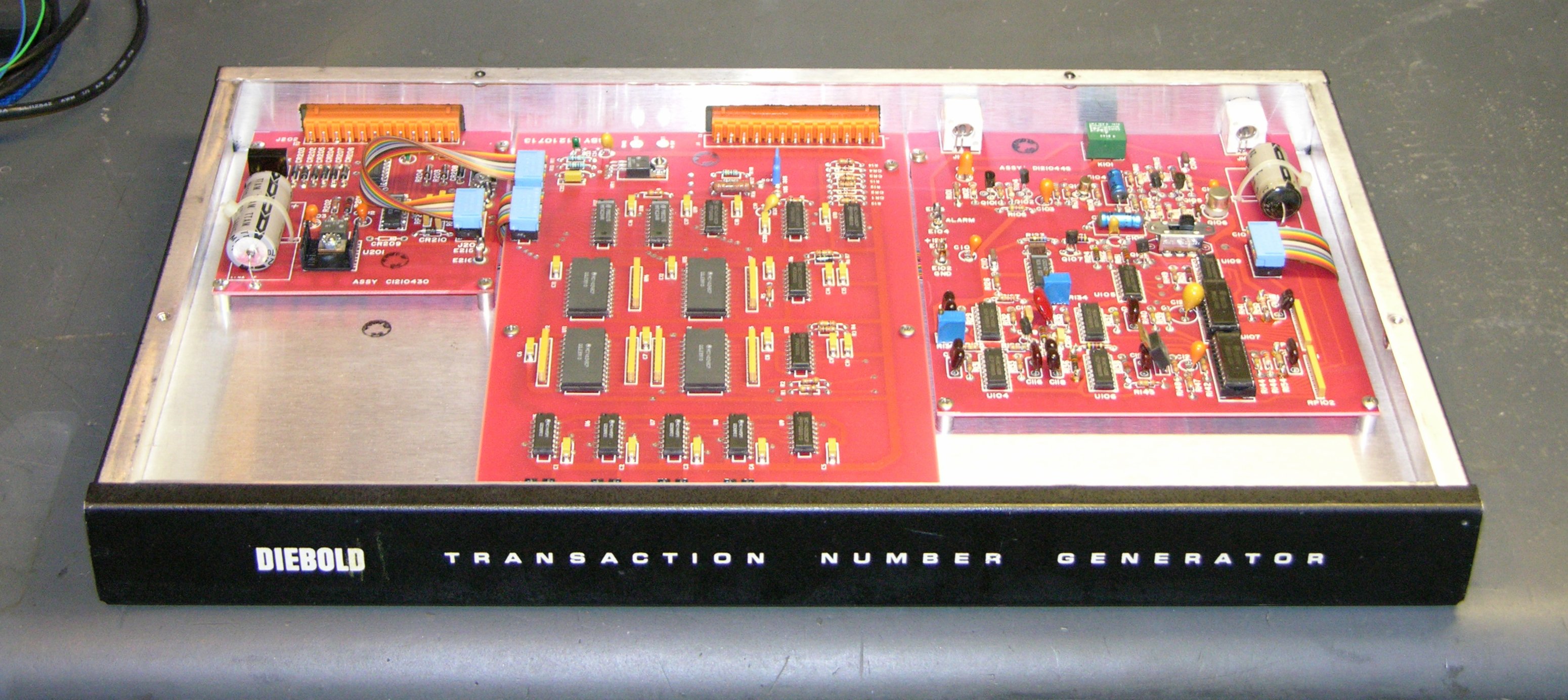
Diebold Transaction Number Generator, front view

My goal was not to reverse-engineer the whole thing, but to get a rough idea how it worked and look over the interesting bits. I think I’m not alone in that when I get a new electronic device, I like to look inside to see what they used to make it work.

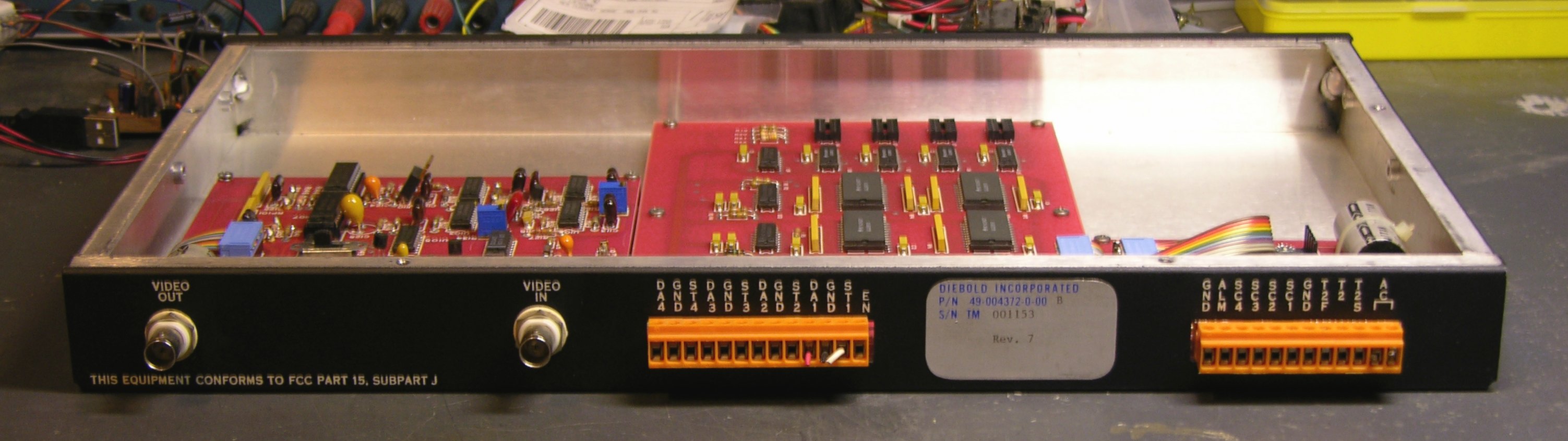
Diebold Transaction Number Generator, rear

The back panel has video in, video out, and screw-clamp wire connectors:

(Nearly) all of my blog pictures are links to the full-resolution version, so you can click to zoom on this, but I’ll save you the trouble. Here are the labels over all the wire connectors:

D
A
4
G
N
D
S
T
4
D
A
3
G
N
D
S
T
3
D
A
2
G
N
D
S
T
2
D
A
1
G
N
D
S
T
1

E
N
G
N
D
A
L
M
S
C
4
S
C
3
S
C
2
S
C
1
G
N
D
T
2
F
T
2
A
C
⌈   ⌉

Okay, so I get what “AC” is, and “EN” might be enable, and “ALM” looks a lot like alarm, and there sure are a lot of ground lines, but the rest of the connections pretty much escape me. The DA-GND-ST triples make me think of some kind of balanced transmission, but wouldn’t a balanced transmission line have a shielded connector instead of a terminal strip?

And why video? Does this box generate transaction numbers and superimpose them on a video feed? I dunno. But it sure is pretty inside. Let’s have a look.

Diebold Transaction Number Generator, interior

I really dig the red circuit boards (red solder mask). Green solder mask predominates these days, and I’ve seen blue and other colors, but I’m pretty partial to red.

The small board in the upper left appears to be mainly the power supply. The medium board in the upper right interfaces to the video feed, and the large board in the middle has some interesting digital logic on it.

Power Supply Board

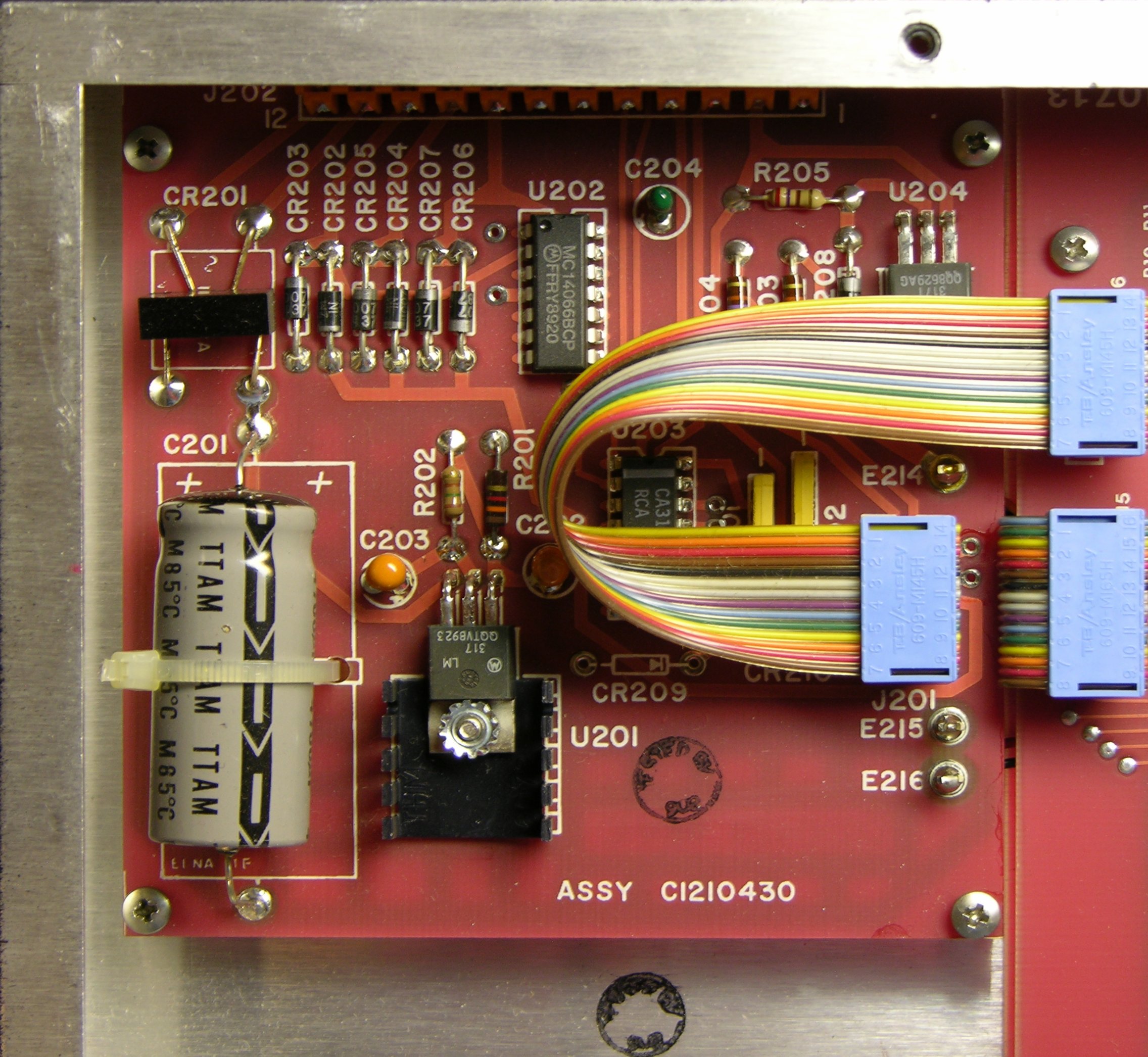
Diebold Transaction Number Generator, small, left board

Here’s the power supply board. The bridge rectifier, CR201, connects to the main AC terminals on the back panel and feeds the LM317 regulator U201. U201 uses R202 (150Ω) and R201 (1.3kΩ) to set its regulated voltage.

The LM317 maintains a nominal 1.25V voltage across its reference terminals, across which R1 thus sets the reference current I1. The reference current also flows through R2, determining the regulated voltage. From the LM317 datasheet,

VOUT = VREF (1 + R2 / R1) + I1 R2

where

I1 = VREF / R1 = 1.25V / 150Ω ≈ 8.33mA

So

VOUT = 1.25V (1 + 1.3kΩ / 150Ω) + 8.33mA 1.3kΩ

    ≈ 1.25V * 1.87 + 10.8V ≈ 13.1V

With a bridge rectifier and capacitor-input filter, output voltage is approximately equal to peak input voltage, which is VAC / √2, so the box is expecting an AC supply voltage of not less than 18.6V; compensating for diode voltage drops gives about 20VAC. Knowing that, I could (if I cared enough) now power it up.

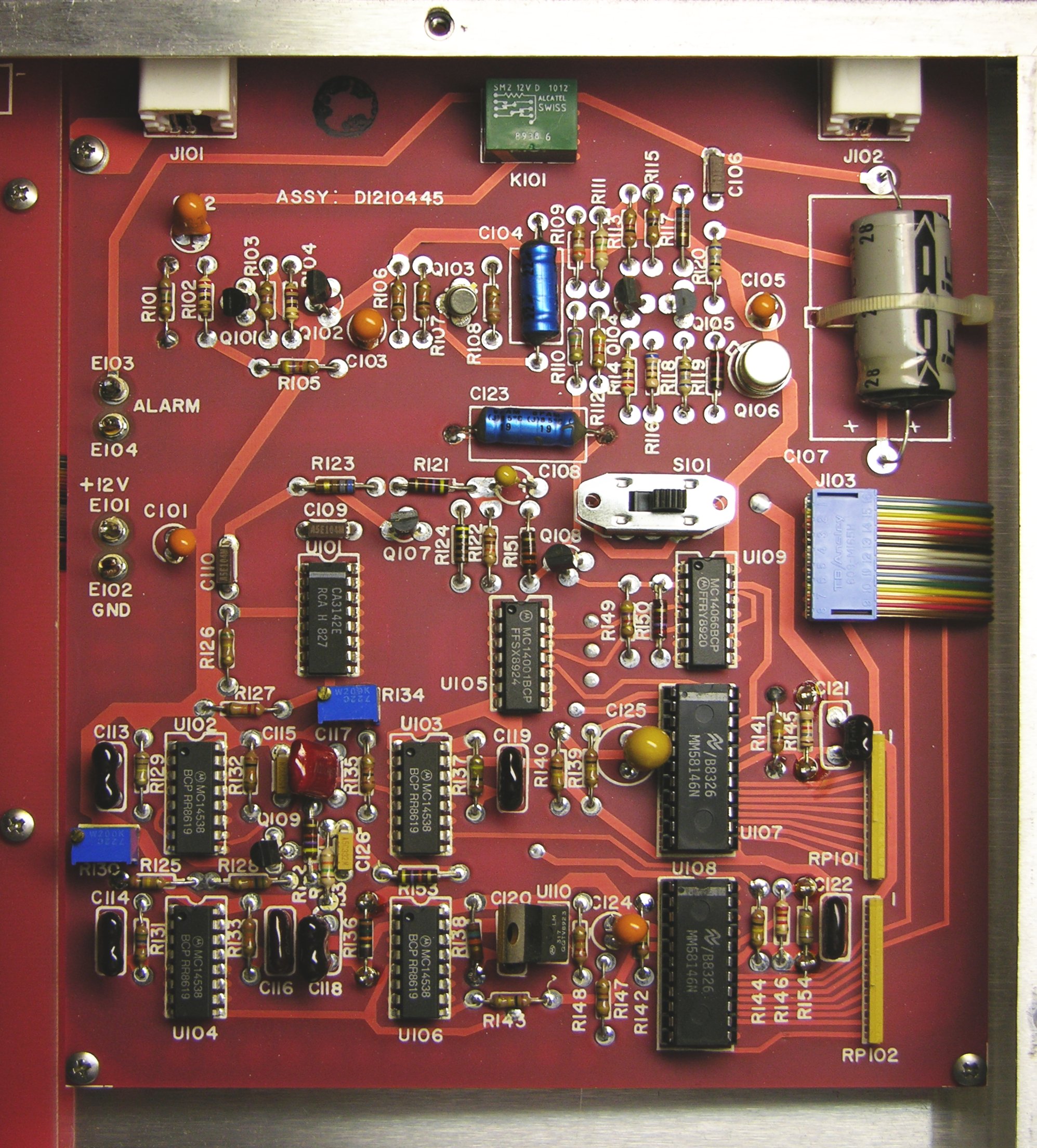
Note the bridge rectifier made of discrete diodes CR202-207 connected to external pins T2, T2F, and ground. CR206 and 207 double in two bridge circuits with CR202-203 and CR204-205, making me suspect that T2 and T2F are not meant to be used simultaneously, but as alternates. On the other hand, T2 heads off to the OUT1 (common) pin of the MC14066 quad analog mux chip. Kind of looks like it’s being switched to one of two different destinations.

Video Board

That’s about as much effort as I care to put into the power board, so let’s move on to the video board.

Diebold Transaction Number Generator, right board

The four chips in the lower left are MC14538 oscillators, there’s another LM317 voltage regulator in the lower center, and the board has a mechanical relay up at the top. But the really interesting part is the two large chips in the lower right: MM58146 on-screen display drivers for television channel indicators. So this box is built to superimpose some kind of transaction numbers onto video. That’s interesting to know.

Logic Board

Diebold Transaction Number Generator, large, center board

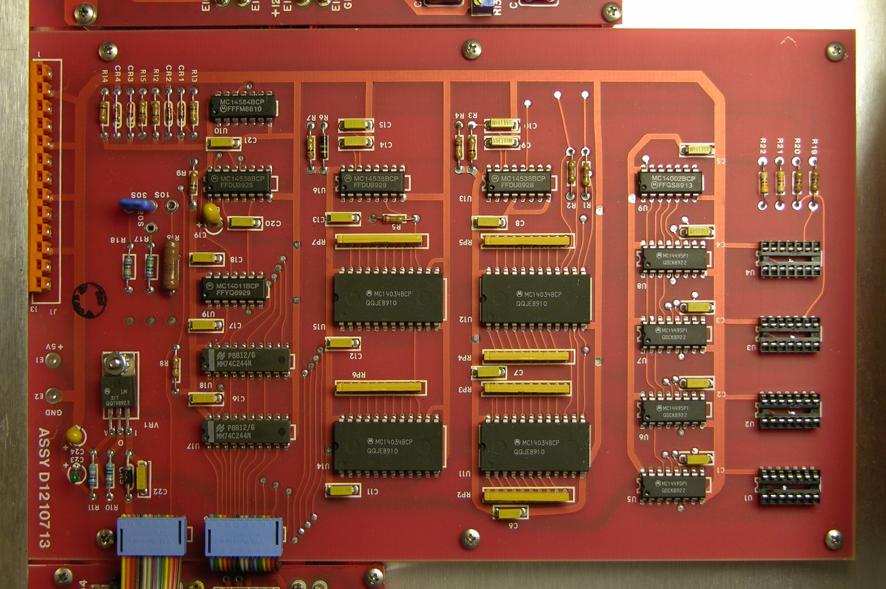
On to the logic board in the center, which I’ve rotated here to make the part numbers easier to read. The four chips U5-8 near the empty sockets on the right are MC14495 hex to seven-segment decoders. Whaaaa? I assume the on-screen display driver chips do their own character generation, so why decode binary to seven-segment? Maybe the four empty sockets U1-4 are for DIP seven-segment displays, to show the transaction numbers internally during testing or troubleshooting.

The four large chips in the middle, U11-12 and U14-15, are even more interesting. They’re MC14034 universal bus registers, permitting bidirectional transfer of data between two parallel buses, serial-to-parallel, and parallel-to-serial conversion.

The datasheet tantalizingly offers, “Other useful applications for this device include pseudo–random code generation,” but says nothing further about it. My guess is you’d wire them to shift and output bits, possibly with external inverters to shuffle things around at different stages, to make a hardware implementation of a PRNG algorithm.

You might even be able to wire them up to make a digital version of something like the rotors from a German Enigma cipher machine — but without spending a lot of time tracing pins on the bottom side of the board, I don’t know whether that’s how they’re being used here, or merely for more mundane purposes. It’s not quite worth it to me to figure out exactly how the MC14034s are used, so I’m pretty well done with my exploration.

Conclusions

I didn’t figure out a whole lot about the device, but it’s pretty clear that it takes a video input and superimposes numbers onto it. (One thing I wondered initially was whether it might be using video as a source of random noise to generate transaction numbers.) And it has some interesting bits inside, with logic chips I might be able to reuse for something else. That’s enough to satisfy my curiosity for now.

MP3 of Noise from Baldwin 45HP2 Organ

September 4th, 2007 by Keith Neufeld

Here’s an MP3 file of the noise the organ is making. It’s about 24 seconds:

  • The pop of the power switch being turned on.
  • Silence and the noise fading in as the tubes warm up.
  • Loud noise.
  • Faint notes — me playing on the keyboard. I could adjust the manual and pedal volumes to any mix I wanted; that’s just where they happened to be set.
  • Fade out after I turned off the power.

Note that the noise is continuous the whole time the organ is on — not just when playing the keyboard or pedals. And my iBook’s internal microphone didn’t capture the lower octaves of the noise at all — the sputter goes down further than I can hear playing back this sample.

Maybe this helps?

Advice Wanted: Troubleshooting a Baldwin 45HP2 Vacuum Tube Organ

September 1st, 2007 by Keith Neufeld

Baldwin Electronic Organ Model 45HP2, back open

My friend Lawrence’s son Jacob has just been given a Baldwin Electronic Organ, model 45HP2. It’s big and old and made with vacuum tubes and point-to-point wiring (no printed circuit boards), and it has a problem: The speaker for the pedals (that you press with your feet) continually puts out static that sounds like a low-pitched crackle. It’s definitely not 60Hz hum, nor does it sound like turntable rumble — it’s very irregular in both pitch and amplitude.

Particularly vexing is that the organ was reported to work perfectly before it was moved 60+ miles in a U-Haul-type trailer. So whatever is wrong with it probably has a mechanical origin — a damaged tube, a part or connector that needs to be reseated, or a joint that needs to be resoldered.

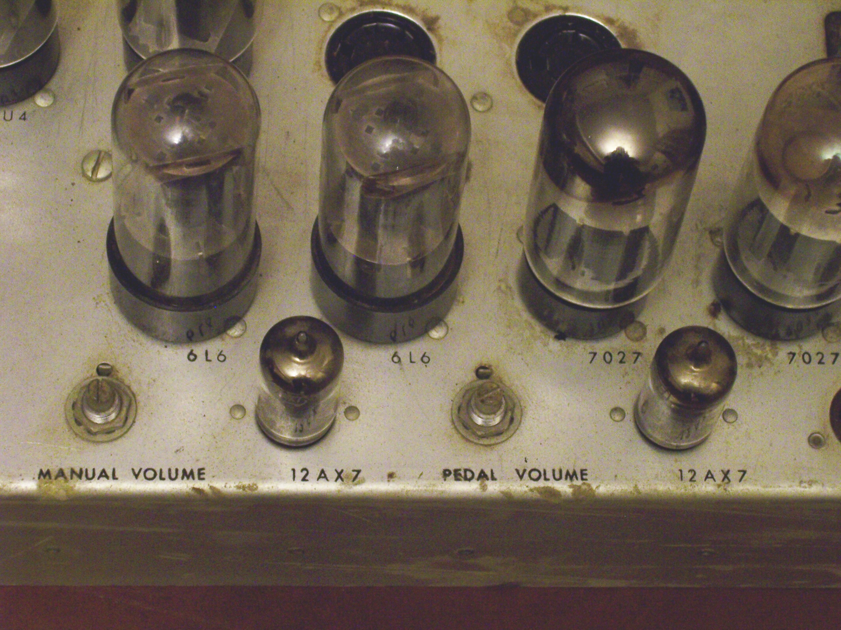
Baldwin Electronic Organ Model 45HP2, amplifier closeup

The amplifier chassis has separate volume controls for the manual (keyboard) and pedal (footboard), and turning the pedal volume all the way down eliminates the noise. So it definitely seems to be coming from the pedal section — either a tone generator or the amplifier.

The problem would be easy to repair if it were a simple matter of replacing a bad vacuum tube, so we’ve started investigating in that direction. I had Jake swap the two 12AX7 tubes on the amplifier to see whether the problem followed the tube to the manual speaker, but no change. I should probably have him swap the 616s and 7027s as well.

Baldwin Electronic Organ Model 45HP2, tone generator closeup

The tone generators run across the upper part of the back of the organ, with a column for each note of the scale, two columns per “board.” I believe the connector at the top brings in the “requests” for that tone in each octave — probably in analog form, as a sum of all the different sources needing that pitch (for a fundamental or harmonic frequency).

The boards are presumably the oscillators, and there’s a bus (I assume the tone output bus) made of 1/8″ rods at the bottom of the inside of the cage. My guess is that the pedal tones go onto a different rod in the bus than the manual tones; but without a schematic, with the high voltages I expect are present in a tube system, and with not much time spent so far, I haven’t tried to determine which one. It’d be fruitful to disconnect the pedal tone generator output from the amplifier, to isolate the problem to the oscillator or amplifier section, if we knew which it was.

All of the oscillator tubes are identical (6SN7 GTB), and I did have Jake rotate them within all the oscillators (top two down one, bottom to top), thinking that if an oscillator tube were the problem, the nature of the noise might change if the tube were in a different position. No change so far.

If there’s anyone out there with experience with this type of thing, I’d be very grateful for any advice you want to throw my way.

Elastomeric Connectors

August 28th, 2007 by Keith Neufeld

A reader named Dave posted a very well-informed comment that what I’ve been referring to as an anisotropic strip (connecting an LCD to a PCB) is more specifically called an elastomeric connector. I thought it was interesting enough to be worth pulling up into a new post:

The anisotropic strip on the LCD is technically known as an elastromeric connector, but usually referred to as a zebra strip. If you examine it closely under a strong magnifying glass or a low power microscope, you’ll see alternating bands of conductive and insulating material, usually something like graphite loaded rubber for the conductive material and unloaded rubber for the insulating material. The graphite loaded rubber gives that portion of the strip a darker colour. Thus, you have alternating light and dark bands, similar to what a zebra looks like. :-)

Dave

Thanks for the detail!

Welcome, Make Readers!

August 22nd, 2007 by Keith Neufeld

Wednesday afternoon:

I never expected this kind of web traffic to my blog, and my current image hosting solution isn’t up to the job.

I’m mirroring right now; images should be back up within a couple of hours.

Wednesday evening:

Images for recent posts should be back up. The remaining images from 2007 are almost done mirroring to the new server, and earlier images will get mirrored if there’s still time while traffic load is still high.

Thursday morning:

Everything seems to be mirrored and working!

Letting the Smoke out of an A3977

August 22nd, 2007 by Keith Neufeld

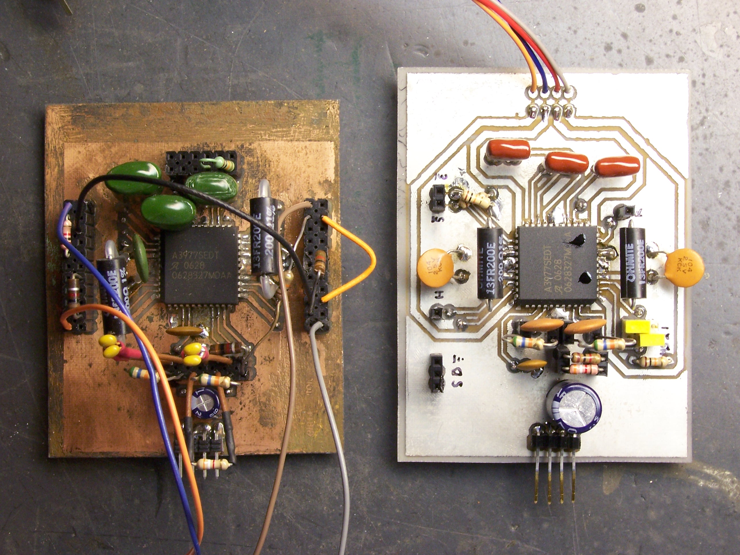
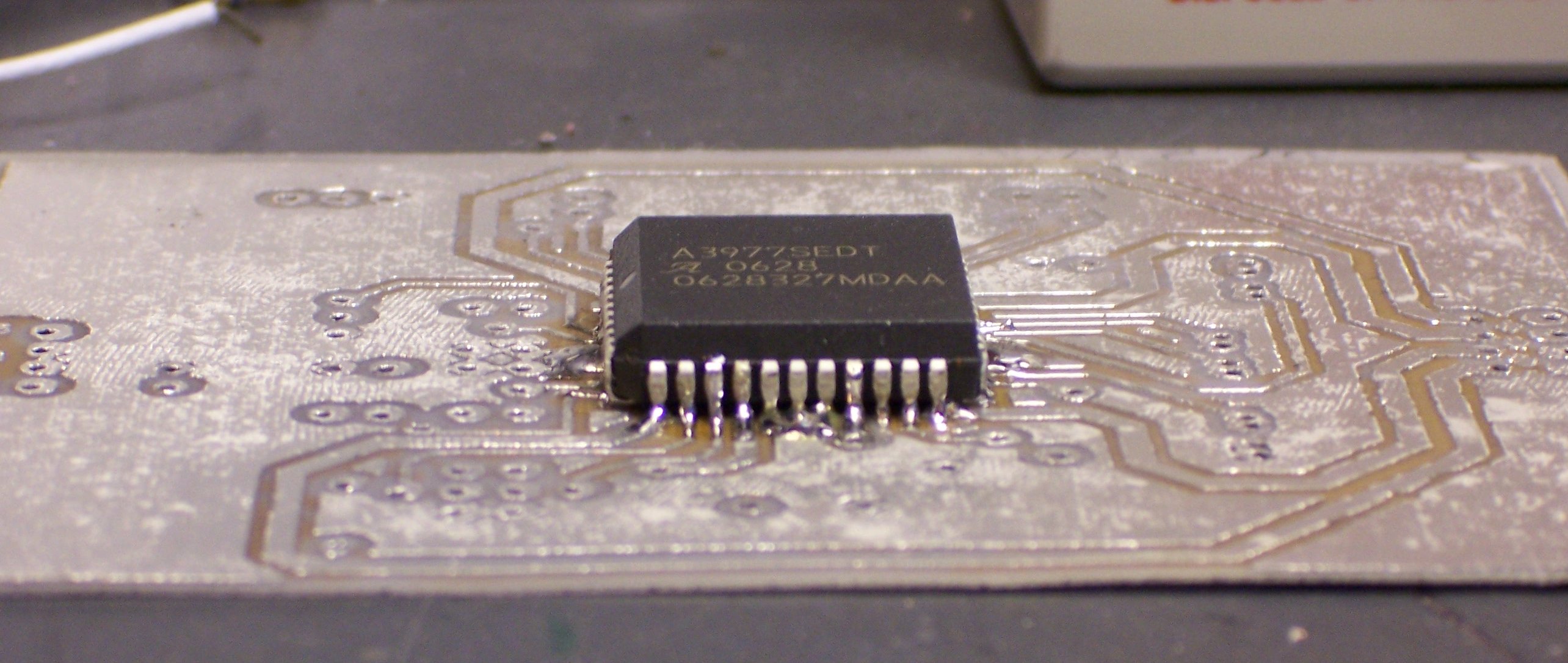
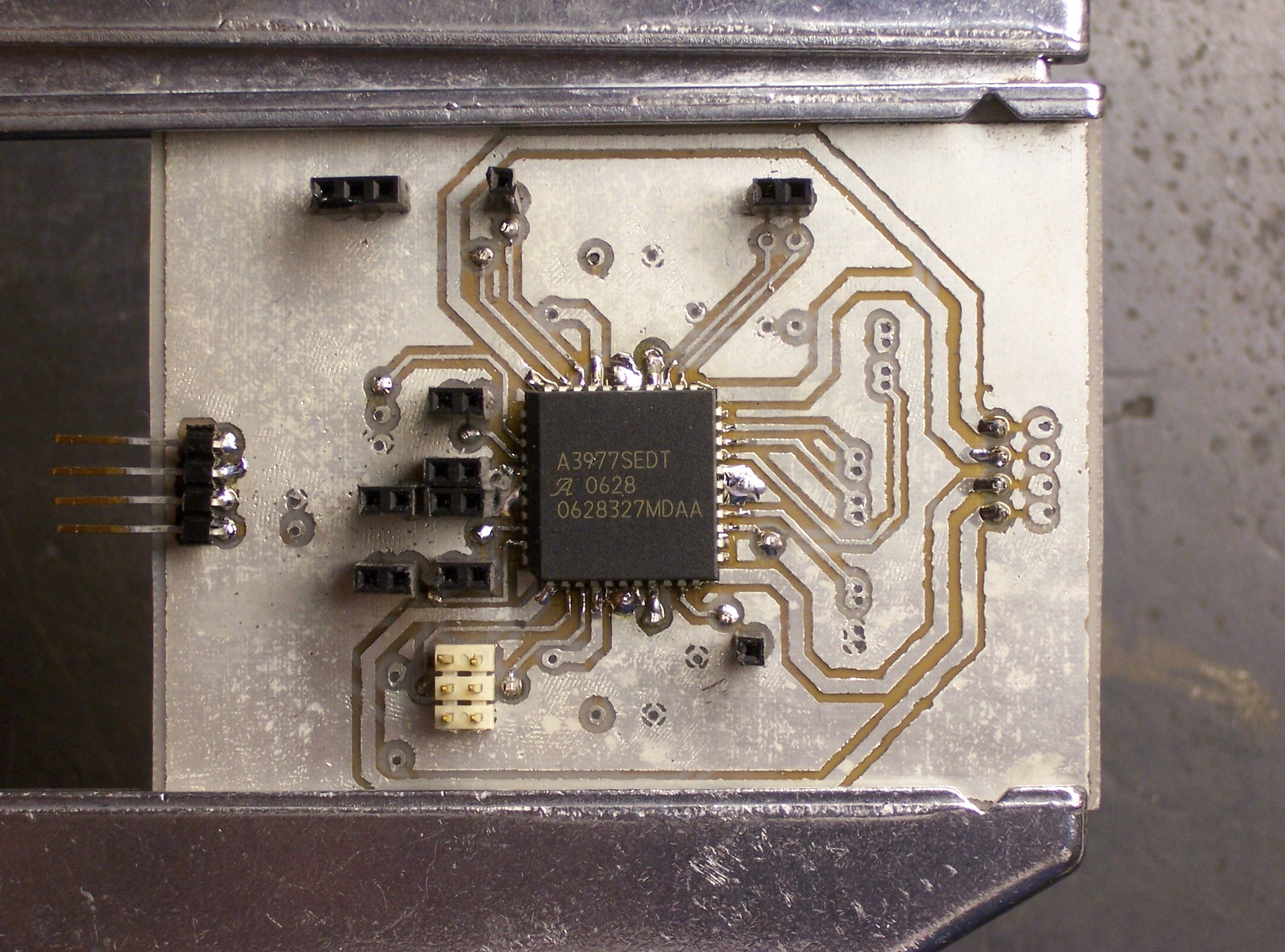
A3977 stepper motor driver breakout boards

What’s the difference between these two boards?

  • The one on the right is prettier.
  • The one on the left has the driver chip soldered in the correct orientation.
  • The one on the left still has the magic smoke.

Tinnit

August 20th, 2007 by Keith Neufeld

Tinnit is a tin-plating solution for coating copper PC boards. It dissolves in water and plates boards without electricity (which standard electroplating requires). The silvery coating prevents the copper from oxidizing, and also takes solder more easily than even clean, bare copper.

I’ve had an unopened package in my PCB-making kit for about eighteen years now. The problem is, once mixed, it has only a six-month shelf life, and I’ve never expected to make enough boards within six months to be worth using up the package.

Yesterday I finally took the plunge, and I’m rather impressed. Everything I did all day worked out pretty well . . . so let me get to the Tinnit in my usual roundabout way. :-)

Stepper Driver on 24-30V

I borrowed a DC power supply from the class lab to test my stepper driver on 24V and 30V load supply. I had got up to 2300 steps per second on 18V, and I hit 2700 steps per second at 24V and ran out of speed on my controller. I’m not using the Arduino’s PWM outputs yet, and 2700 steps / second seems to be about as fast as my program goes using software-based stepping.

I’ve been running the motor in half-step mode because it’s noticeably smoother, at least at lower speeds. But that also means I only get half the motion for each step signal I send. For the sake of testing top speed, I rejumpered the driver board for full-stepping and tried again.

The motor was immediately jerky and twitchy, like it had been with inductive sense resistors. Not only was the top speed drastically lower, but it took great care to ramp up to the top attainable speed. I jumpered back to half-stepping — and the problem didn’t go away. I checked all my connections, measured parts of the circuit, swapped the motor, put a scope on the sense resistor terminals — no go.

I broke it. Still don’t know how.

I’d been planning to build another driver board soon anyway, to drive a second axis prototype. With my first board misbehaving, I could also use the second board to help troubleshoot the first.

I also had a list of changes to make — things that were inconvenient about my first A3977 breakout board. I updated my layout Saturday with (among other things) nice jumpers for option settings, better grouping of signal inputs and outputs, and less reliance on having to solder leads on both top and bottom sides to carry signals through unplated vias.

Hand-Drilling and Etching the PCB

PC board stock, copper pattern, and center punch

Normally I’d use Joel’s CNC machine to drill my board, but the timing didn’t work out this weekend. Instead, to prepare for hand-drilling, I taped together two sheets of my thin double-sided board stock with a printout of the top-side copper pattern and used a center punch to mark the holes.

Alas, I was a bit overzealous with the center punch.

PC boards, holes overpunched

The dimples went through both boards in the stack. Yeah, thin board stock.

I drilled the holes carefully with a #71 bit, then used a hammer to flatten the dimples on the anvil surface of my bench vise. Apparently I did a good enough job, because I made a nearly flawless two-sided iron-on transfer on glossy paper (not even bothering with Press ‘n’ Peel Blue), using the paper towel between the iron and the board again to distribute the pressure.

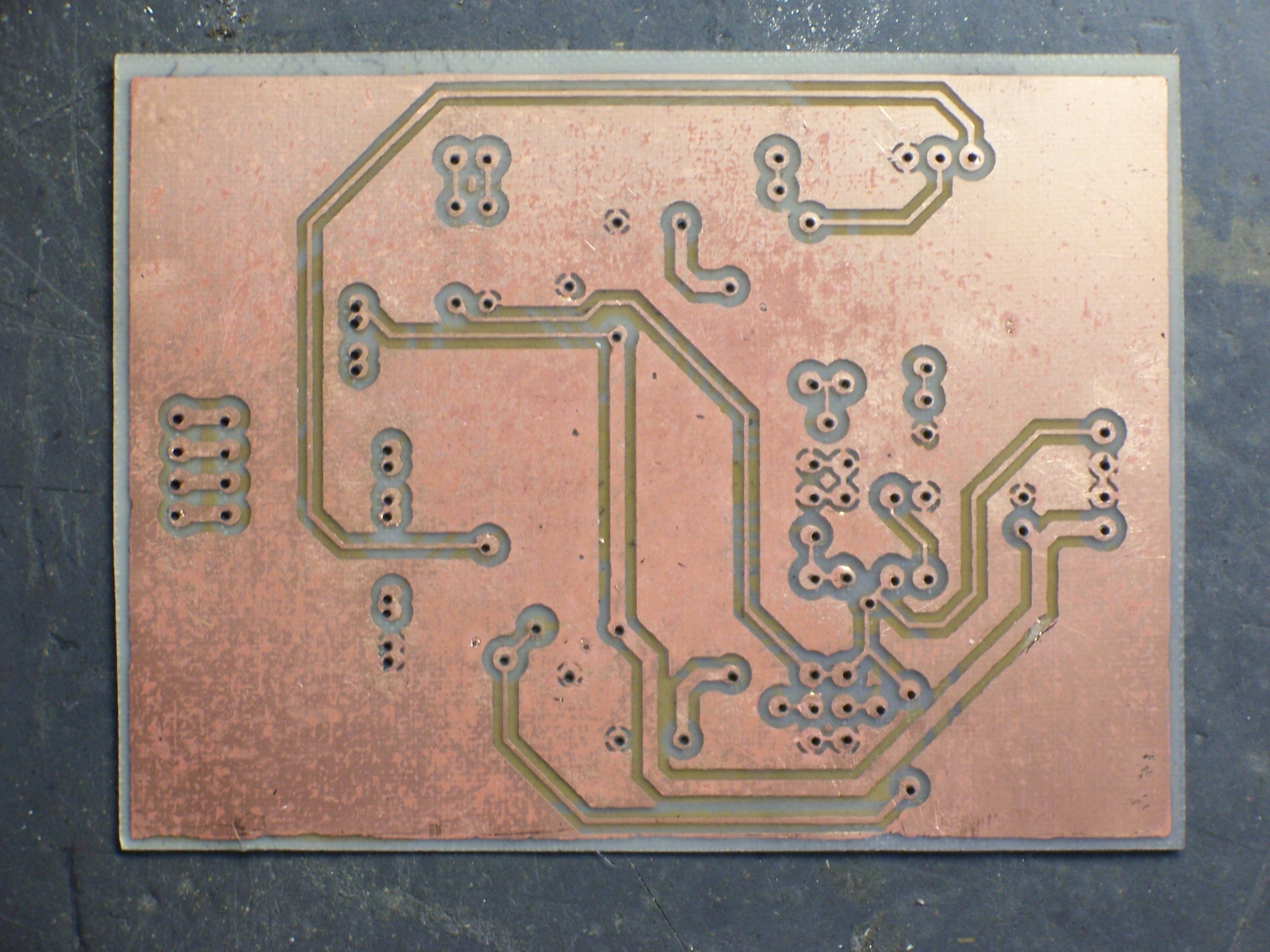
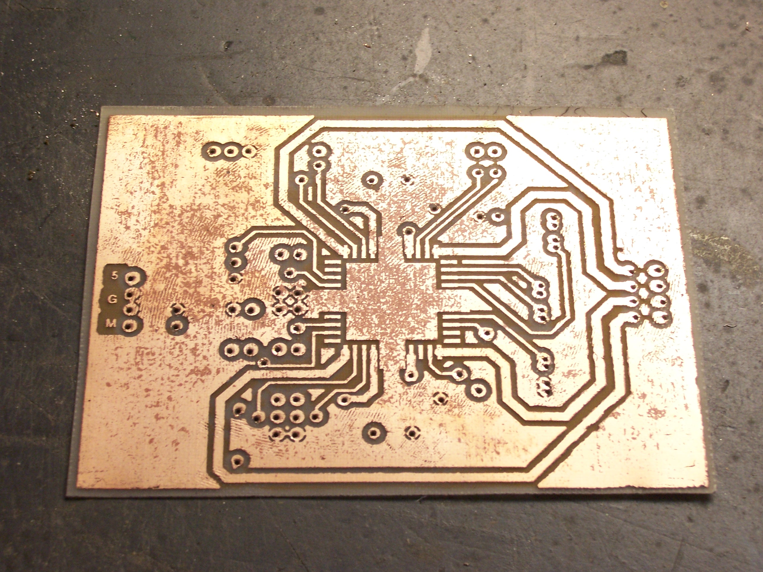
Etched PC board

The board came out as nicely as any I’ve done. I used 16 mil traces and 40 mil isolation, so it wasn’t particularly challenging. Still, it etched very cleanly.

Etched PC board with pockmarks

I did have a little trouble with pockmarks in some of the large copper areas. They don’t impact the performance — just the appearance. I could perhaps have sanded and polished the board to make it prettier; maybe next time.

Tinnit

On each of the last two PC boards I made, after partially populating the board, I really wished I had tried using the Tinnit. And I’m making more boards now — I know I’ll make at least one more stepper driver board (for the third axis), and probably lots of other things, in the next six months. So it seemed like a good time to try it.

The instructions say to mix the Tinnit powder package with 12 oz of hot water, then add enough water to make a pint. To plate a board, heat the solution to 120-140°F in a pyrex container, then dunk the board for 35-40 minutes, agitating every five. Store the leftover solution in a metal-free container.

Well, my package had two smaller powder packets in it, and it wasn’t clear whether that was two doses or two parts of a single dose. Nor could I find any help online. I took a chance and poured in both packets; and when the second packet caused it to start foaming, it was clear that they weren’t the same and both packets were in fact required.

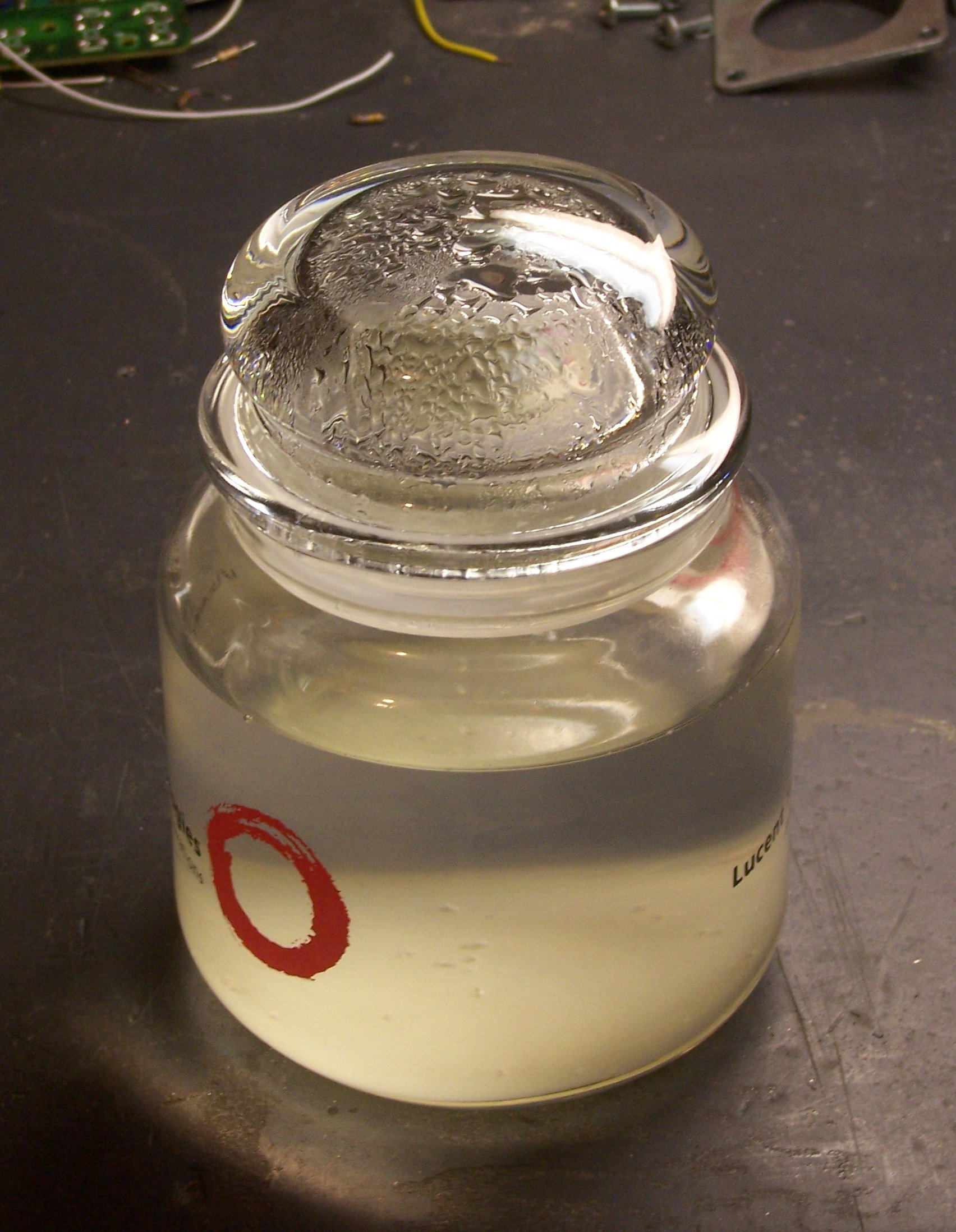
Tinnit solution in glass jar

I mixed the solution in a glass candy jar that I got from a vendor about eight years ago. The jar was just big enough to dunk yesterday’s PC board, so I sidestepped a search for an appropriate separate pyrex container for heating the solution. I put the whole jar (minus the lid) onto a stove burner turned to low and checked the temperature and stirred frequently (with a plastic spoon). It’s not obvious from this picture, but there’s a flaky white precipitate at the bottom of the jar that only went fully into solution at about 130°F.

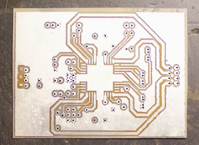
Tinned PC board

The board started turning silvery almost immediately, and coverage didn’t change visibly from about ten minutes in solution until forty minutes when I took it out. I washed and scrubbed it pretty thoroughly, and it still smells like salts.

The result is very shiny and silvery. The pockmarks are still visible — Tinnit (and electroplating in general) doesn’t cover to enough depth to smooth a rough surface — but the board looks pretty good.

PLCC soldered to board

I’m particularly impressed by how much of a difference it makes in soldering. I know it’s easier to solder tinned components, but clean copper takes solder reasonably well. Still, this was amazingly easier to solder. When I built my first A3977 breakout board, I was flowing solder across multiple PLCC leads and cleaning up solder bridges; last night, I was able to solder individual leads with my SMT soldering tip.

PC board with monochromatic components

As I was stuffing jumpers and headers, I noticed how monochromatic the board was without the resistors and capacitors installed yet. I finished all the black, silver, and white components and stopped for the evening. Tonight I expect to add the passives and hopefully get the board up and running.

A3977 Stepper Driver and Higher Load Supply Voltage

August 15th, 2007 by Keith Neufeld

According to the explanation in my previous post, the Allegro A3977 stepper motor driver should be able to run motors faster with a higher load supply voltage. Naturally, I was eager to see this for myself.

Yes, yes it does.

Throwing Together an Unregulated 18V Power Supply

I’d been using my benchtop PC power supply for both 5V logic and 12V load supplies. After swapping the sense resistors this weekend and improving my step rate from 600 steps per second to about 1450, I was really curious how much of an additional improvement I’d get from a higher load supply. The 3977 is rated for a 35V load supply, but some forum posters recommend going no higher than 30V, so I was looking to try out 18-24V.

Joel just dismantled a photocopier with 20V motors; but after looking at the power supply boards, it wasn’t obvious which of the several power supplies was the one providing 20V. Plus they were switching supplies, and I don’t know whether they had integral loads or whether I’d have to provide a minimum load externally . . . bluck.

So I hacked together my own ~18V supply.

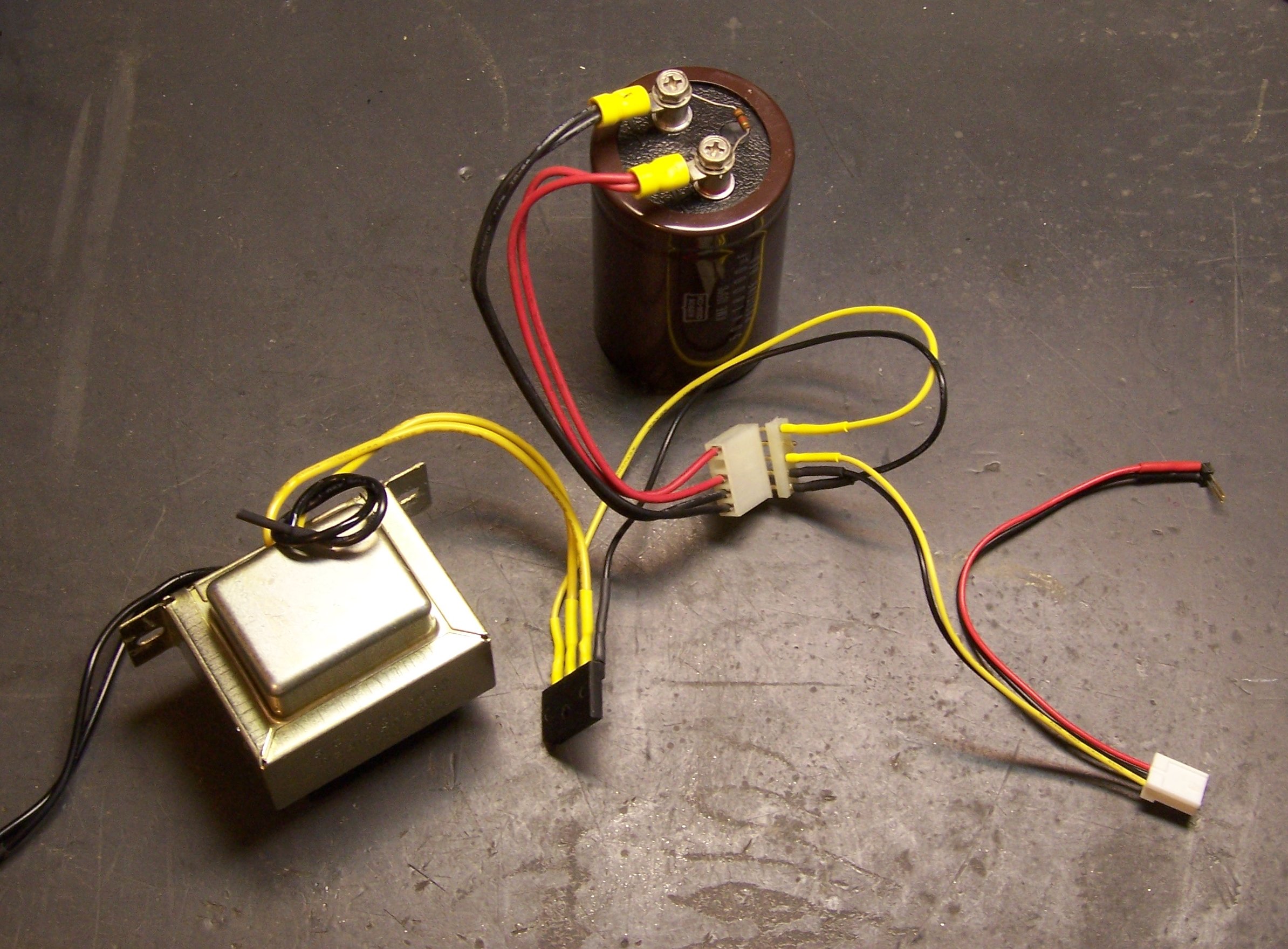
18VDC 3A unregulated power supply

From left to middle to top, that’s a brand new Radio Shack 12.6V 3A transformer, 4A bridge rectifier from a dead PC power supply, and a 18000μF capacitor out of a workhorse Accel printer from a former employer. The line cord is from a broken coffee grinder, the five-pin socket came with the capacitor and the plug from Slim, and the remaining wires and connector are from the PC power supply.

Side note: I’ve seen a few big capacitors in my day, but these impress me. When servicing these printers, I once vaporized a chunk out of my pocketknife’s screwdriver blade when I discharged the big capacitor by accident. I know personally that the last time this capacitor’s printer was powered on was no more recent than 1998. On a lark, after getting the capacitor out of the printer, I put a voltmeter across it, and it still had 3V on it. Ran an LED for a couple of minutes while I was draining it. I screwed a 1KΩ resistor across it to drain it a little faster in my power supply, so I don’t have to worry as much about hurting myself.

Power Supply Calculations

I have never kept the formulas for different rectifiers in my head, so I’ll run through the numbers for this one here. The transformer’s secondary (V2) is 12.6VAC RMS, and the peak voltage of a sine wave is RMS * √2, so the secondary peak voltage (VP2) is

VP2 = V2 * √2 = 12.6V * √2 ≈ 17.8VDC

The peak DC output of a bridge rectifier (VP) is the peak secondary voltage minus the two diode drops, so

VP = VP2 – 1.4V = 17.8V – 1.4V = 16.4V

The output of a capacitor input filter is the same as the peak DC value of its input, minus load-dependent ripple, so I should be getting about 16.4VDC out of this setup. Measured about 17.1, so I’m in range. The transformer is rated for 12.6VAC output at 3A, so it’s almost certainly putting out a little higher voltage with such a light load. If I weren’t so lazy, I’d go measure it, but that’s out of the question. :-)

And there’s no regulator. Linear regulators convert electricity into heat, and I need neither less electricity nor more heat. The A3977 is effectively a switchmode regulator for the motor coils anyway; so by regulating its input load supply voltage too carefully, I’d just be duplicating effort. Especially for a test. Note that I’m still running the logic supply voltage from the well-regulated 5.0V output of my PC power supply — the red and black wires in the photo above are picking that up and adding it into the four-pin supply jack.

With my scope across the capacitor terminals, I estimated .2V peak-to-peak ripple when running one motor at full speed. That’s pretty lousy ripple for most digital or analog circuits, but by all appearances just fine for this application. Especially, as I intend to keep pointing out, for a test. :-)

And Yes, the Motor Runs Faster

The motor is running noticeably faster before losing steps — up from 1450 steps per second to about 2300 steps per second. That’s an improvement from 2.8 seconds per inch of linear travel to 1.7 seconds per inch — a considerable difference for something as simple as changing the load supply voltage.

I want more, of course. I still want to see what happens at 24V and at 30V, so I bought a bargain 24V power supply on eBay today. When it gets here, I’ll give it a shot.

It’s worth noting that as far as I can tell, I don’t need to change anything in the A3977 circuit to adapt to the new load supply voltage. The sense resistors determine the maximum current that should flow through the motors, and the whole job of the 3977 is to keep that the same regardless of supply voltage. And I provide VREF from a divider on the logic supply voltage, so that’s also independent of load supply. Slick.

A3977 Stepper Driver REQUIRES Non-Inductive Sense Resistors

August 13th, 2007 by Keith Neufeld

The stepper motors I’m using to build my CNC machine are rated for 2.5A. Now, when they’re holding one position, it’s easy to deliver 2.5A of current. But when the motors are rotating, their coils are being energized one at a time in sequence.

The coils are inductive, and inductors resist changes to current. So when a coil is first energized, it takes a moment for the current to build up to capacity. As a result, with a simple stepper driver, the faster you turn the motor, the less of the time each coil gets full current, and the weaker the motor gets.

The Allegro Microsystems A3977 stepper driver chip I’m using to control my stepper motors overcomes this by running at a (much) higher supply voltage than needed to deliver 2.5A, and by using sense resistors in series with the motor coils. When it’s time to energize a coil, the A3977 delivers the full supply voltage and watches the sense resistor. When the desired amount of current is flowing through the resistor (hence the motor coil), the A3977 shuts off the voltage (briefly), then ramps it up again. The result is the delivery of the desired current on average, but with a much more rapid start due to the higher supply voltage.

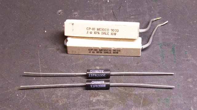
Buried within Allegro’s A3977 FAQ is the recommendation that the sense resistors should be non-inductive. Since the values required are the sub-ohm range, commonly-available resistors are in big sand packages — and as noted by Jeff Mann in a comment posted about my control board, are internally wirewound and inductive.

Sand resistors and non-inductive sense resistors

I had already bought Ohmite non-inductive sense resistors from DigiKey, which are also much smaller and more manageable than the big sand resistors. (The cross-section of the sand resistors is about 1/2″ square.) I hadn’t worked on the stepper driver in quite a while, though, and I hadn’t put in the noninductive resistors yet.

Did that Saturday. The difference in performance is amazing.

Performance Gains

The last time I did a speed test of my stepper motor controller, I was able to get about 500-600 steps per second before the motor started losing steps and stopped turning. Additionally, it growled and twitched when it was idle, and grunted and jerked at low speeds, smoothing out only at higher speeds.

A3977 stepper control board

With the non-inductive resistors installed, all the growling and twitching went away. (Someone should look at non-inductive resistors for bulldogs, but I digress.) I’m able to ramp the motor up smoothly from a stop to full speed.

And full speed has increased from about 600 steps per second to over 1450 steps per second, just from installing non-inductive sense resistors. With my 200 step/revolution motors and 20 tpi all-thread, that’s an improvement from about seven seconds per inch of linear travel to about three seconds per inch.

That’s still running on 12V out of my spare PC power supply, and I’m trying to rustle up a 24V supply to test with, which should increase the speed further. That’s also without tweaking the A3977′s component values — I hear there are some tricks to play there, too.

Executive summary:

Inductive sense resistors with the A3977 make the motor growl and jerk when idle and at low speeds, and limit maximum speed. Non-inductive sense resistors with the A3977 make the motor smooth and quiet at all operational speeds, and dramatically increase maximum speed.

Z Axis Completely Assembled

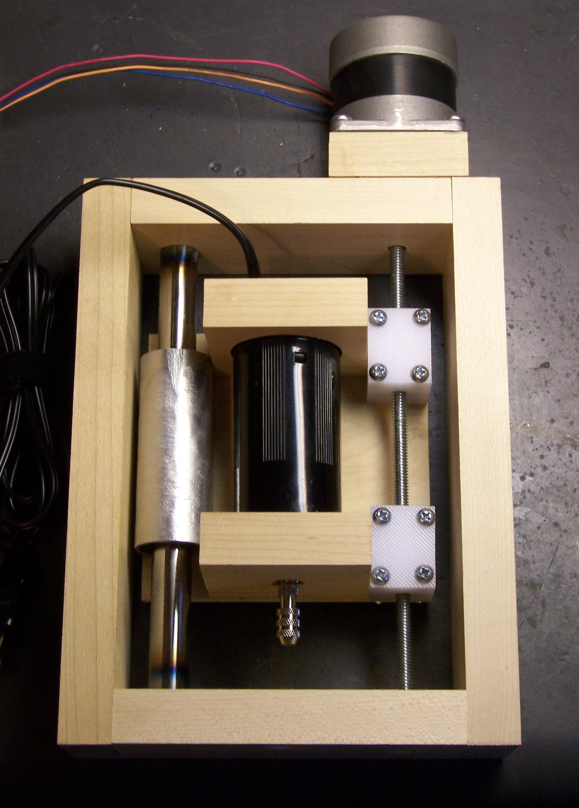
frame

I have the drill sled mounted in the frame, the motor properly mounted, and the joystick controlling it at variable speed. Next step is building the Y axis around the Z frame.

Credit Where Due

Many thanks to Jeff Mann for his original comment, which drew my attention back to replacing the sense resistors, and for our followup conversation, which helped me understand and think through how the PWM driver makes the motors work better at higher voltage without going over the rated current.

Rewiring a Game Controller’s Joysticks

August 13th, 2007 by Keith Neufeld

When the CNC machine is finished, it will of course be controlled by a computer. But during development, it’ll be handy to test it with other controls, like joysticks. I had in mind to use analog joysticks, so I could control motor speed as well as direction.

Unfortunately, I couldn’t find the analog joystick element that I bought from All Electronics. (That this happened something like nineteen years ago may have a little to do with why I can’t find it right now.) Fortunately, a poll of my friends for an analog joystick I could borrow yielded this game controller that Jeremy had already brought me in a batch of electronics junk:

USB game controller

In his own words:

Didn’t like it because it was crappy. The retractable cord (while an OK idea) was too short and stiff. Its real downfall was that the buttons were sticky. They wouldn’t pop back up immediately when pressed so rapid tapping was impossible. More frustrating than useful.

So, perfect for me to butcher for my own purposes.

Inside the Game Controller

My first thought was to extract the analog joystick elements, so I opened the case and dug in.

Game controller with case open

Here you can see all the guts that make it work. The upper half of the picture is the bottom side of the case, with the retractable USB cable recessed under the PCB, and wipers on the PCB to make contact as it spins.

In the handles near the bottom of the picture are small motors with eccentric weights for “force feedback,” and directly above them at the center of the picture are the pushbuttons on the forward edge. The tan PCB has contacts for the pushbuttons, LEDs, and pseudo-joysticks on the top face; and the green PCB is the brains of the outfit.

Game controller, main board

The main board holds the analog joysticks (the solder pads surrounding the silk-screened circles in the lower left and right) and the USB interface (in the black blob).

Game controller, joystick mounting

Flipping the main board makes it easy to see how joysticks work. Each is a clever cage with a gimbal mechanism for the stick, connecting to two potentiometers (visible above and to the right of the right stick). These joysticks also have pushbutton action (like clicking the scrolly-wheel on a mouse), so there’s a stick coming out the lower side to a switch housing.

I had actually completely desoldered one of the joysticks when I stopped to think about how I was going to mount them — loose, to a board, what? How about . . . in a game controller case. Duh.

Rewiring

So I soldered the joystick back in and started to look at the circuit. The USB interface was useless to me since I wanted direct access to the analog controls, but I could still use the board as a carrier for the components.

The controller had the potentiometers wired as variable resistors (the wiper tied to one leg, probably for the blob to measure resistance with an RC timer), but I wanted potentiometers so I could measure voltage with an A/D converter on my microcontroller. So the first order of business was cutting traces.

I used a knife to cut through the traces tying the potentiometer wipers to the legs, and the continuity meter to makes sure I’d cut thoroughly enough. Then I identified which direction I wanted to be 0V and which 5V (moving the joystick to the upper right should deliver 5V on each axis), labelled potentiometer terminals with + and -, and started jumpering together pads that hadn’t previously been connected, to distribute power and ground to all the potentiometers.

And that’s how far I got in May, when I last worked on it. I picked it up again this weekend and finished the job.

Game controller, rewired for direct access to analog joysticks

I severed all the connections around the processor blob, since I didn’t need it and didn’t want it getting confused by the new arrangements. And I soldered on wires from a supple new cable Joel gave me (salvaged from who-knows-what). I provide 5V and ground on the grey and black wires, connected joysticks on brown-red-orange-yellow, and have blue and green left over for pushbuttons when I figure out which ones I want to use.

On the loose end, I soldered a header pin to each wire, to fit nicely into prototyping sockets, and heatshrunk each solder joint. I also heatshrunk logical pairs of wires together, to make it easy to remember which wires go together to a potentiometer. You can see that end in my previous post on the Arduino.

I made one mistake, which I had to go back in and correct: I wasn’t thinking straight about which potentiometer was the X axis and which was the Y. The one across the bottom, of course, is the X axis, and the one on the side the Y — but that’s not how I wired it. I swapped the brown and red and orange and yellow wires from what’s shown in the shot above.

And it works great! I have it reassembled and the right joystick controlling the prototype Z axis of my milling machine . . . which I’ll talk about next.