Archive for the ‘CNC’ Category

Soldering My Last Two MakerBot CupCake Stepper Boards

Monday, May 18th, 2009

Over the weekend I received the three missing electrolytics, and yesterday I built the other two stepper driver boards.

MakerBot CupCake stepper driver board with flowed, half-melted solder paste

Just one noteworthy item — I meticulously lined solder paste on every IC pad, and then during the “soak” period of reflow (also known as “the time it takes my 500W heater to creep the plate up to 185°C”) the paste all slumped together anyway. (Forgive the poor focus in the picture; my camera’s not very good and that’s the best I could get.)

When the solder paste reflowed, surface tension pulled it all into nice little fillets anyway.

Lesson: Don’t bother tracing every IC pad with solder paste; just run a bead perpendicular to the leads and trust surface tension.

Also, I had one solder bridge during reflow. I took a small screwdriver and poked it between the leads, breaking the surface tension and the bridge. Nice trick, and a quicker (and cleaner!) fix than anything you can do after the solder cools.

Assembling the MakerBot CupCake Extruder

Monday, May 18th, 2009

I’ve been plugging away at the CupCake “Plastruder” in the evenings, and I now have the mechanical assembly mostly finished, pending the arrival of some custom parts.

MakerBot Plastruder plastic extruder

I’m delighted by the clear plexiglas design. And having the mechanical assembly — particularly the extruder — put together really highlights how small this thing is. That’s not a bad thing — for a given build capacity, the smaller the machine is, the better.

(more…)

Soldering the MakerBot CupCake Extruder Controller

Friday, May 8th, 2009

Over the last two evenings, I got my CupCake’s extruder controller assembled.

RepRap extruder controller

I have just a few notes below following up on solder paste, hotplate soldering, and missing and unlabeled parts.

(more…)

Assembling the MakerBot CupCake Stepper Controller (or My First Reflow Solder)

Tuesday, May 5th, 2009

Having got my reflow soldering hotplate assembled Sunday, last night I sat down to build the first stepper controller for my CupCake rapid prototyper. Besides being the first of the CupCake’s stepper controllers, this is also the first thing I’ve ever reflow-soldered, EVAR (although not the first SMT I’ve soldered, as I’ve done that by hand before).

RepRap (MakerBot CupCake) stepper driver on hotplate, assembled and ready to reflow solder paste

There are lots of solder paste and solder reflow tutorials online, and that this ain’t. This is just my observations about parts of the process I hadn’t previously picked up from reading.

(more…)

Makerbot Cupcake Opto Endstops

Friday, May 1st, 2009

I’ve been massively interested in the RepRap project since I first heard of it a few years ago. RepRap — short for replicating rapid-prototyper — is a CNC machine to extrude hot plastic and build up a model additively, like a robot hot-glue gun. It promises to lead the affordable desktop fabrication revolution, printing at home on a sub-$1000 machine what the aviation lab at work printed for me on a $30 000 machine (which itself is already orders of magnitude less expensive than the ones I saw in use when I worked at Cessna Aircraft).

The RepRap can replicate many of its own parts — so once you get one, it’s a matter of feeding it plastic and a few hours (and motors, and circuit boards, and commonly-available hardware) and you can have another one for your friend. It should be pretty viral once it gets going — but getting going is the problem. Even with various “RepStrap” (RepRap bootstrap) designs, the barrier to entry to build my own from scratch was still a bit too high for me — particularly for the heater/extruder nozzle.

So when I saw that Zach “Hoeken” Smith (a member of the RepRap team who’s designed most or all of the current-generation electronics), Bre Pettis (the “talent” on the first Make Magazine videos I remember seeing), and a couple of guys I don’t recognize (sorry, couple of guys!) had teamed up to found MakerBot and were selling the CupCake CNC kit, a complete set of parts to build a RepRap-compatible machine, I was onboard in a heartbeat. The price still feels a bit steep, but the time was right and I got one of 20 presale kits.

It came last week and what with other obligations, I haven’t even had time until last night to start working on it. So I’ll be doing this a slow step at a time; and the first step was assembling the through-hole optical endstop PC boards.

Complete set of Makerbot CupCake opto endstops

The CupCake calls for six endstops — two for each axis — and they use RJ-45 cables for most of the connections, but three-pin headers for the Y axis due to space considerations.

The boards are nicely made; I like it a lot that they’re no larger than they need to be; and I really enjoy the red.

RepRap opto endstop optointerruptor alignment

I have only a couple of cautions for assembling these. First, as noted in the CupCake electronics assembly instructions, the PC board’s optointerruptor footprint is a little off, and it takes some shoving to get the mounting holes aligned. This does matter because these holes are how the board mounts to the chassis, so take the time to get them as close as possible.

RepRap opto endstop RJ-45 jack modification

Second, use a chisel to shave off that spacer tab on the underside of the RJ-45 jacks. If you don’t, they won’t sit flush, and that bothers me.

RepRap opto endstop RJ-45 jack fit with and without modification

Take my word for it, it’s way easier to do this before you start soldering the pins.

ABS Puck Case Prototype

Saturday, March 14th, 2009

Dimension Elite 3D Printer

A while back, I had contacted Brian Brown, associate director of the CAD/CAM lab at the university’s National Institute for Aviation Research and a great colleague of mine, to ask whether they had any rapid-prototyping machines that could churn out a prototype LED puck case in a transparent or translucent material.

Dimension Elite 3D printer

They didn’t at the time, but Brian contacted me last week to say that they had a new Dimension Elite 3D printer and they’d be happy to print me a case while they were ramping up on learning to use it. I emailed over an STL export of my Blender model, Brian put his student Jonas Fink to work, and the next day I went over to take pictures of the machine in operation.

As it turns out, the “natural” colored ABS plastic isn’t translucent enough to use as a functional test enclosure, but it makes a great physical prototype. More on that in a bit.

How It Builds

Dimension Elite 3D printer building support structure

The machine extrudes a tiny “string” of ABS plastic onto a removable tray. It first lays down a brown support structure to hold up any overhanging areas, and the support material is a soluble form of ABS that’s later removed in a detergent bath. The extrusion head moves around one entire horizontal plane, “drawing” in all the material that appears there, then lowers the tray slightly and draws in the next layer.

Dimension Elite 3D printer beginning to build puck case

Once the support structure is in place, the machine extrudes plastic for the actual model — still continuing to build support structure for higher overhangs. My puck case was being built upside-down (as a bowl instead of a dome); so here you can see the puck material in the center as the machine works its way out from the low center of the bowl up the curved edges.

Breaking It Loose

Completed ABS puck case prototype, front view

The build ran past the end of the work day, so I went back the next morning to see the completed prototype, still attached to the tray. If you look closely, you can see the layers of “threads” that were used to built up the model, with the support structure underneath.

Completed ABS puck case prototype, support structure upper front

After breaking the model free of the tray, the sparse honeycomb-like nature of the support structure is even more evident. The light ring in the middle is the bottom-most layer of model plastic surrounding the hole for the pushbutton switch.

Although the suggested means of removing the support structure were to put the whole piece into the cleaning tank for a few hours and let it dissolve, I was curious how sturdy the support was and found that I could actually pry and crack it loose of my model using my pocketknife. I managed to get the whole thing cleaned off without using the tank or cutting off a finger.

The Result

ABS puck case prototype

The finished prototype is rougher on the top than I expected — this machine (at least as programmed for this run) doesn’t seem to build a smooth finishing surface on the support structure before beginning to build the model, so the first surface of the model has the jaggies. You can easily see the contour become smoother around the knee of the curve, where it stopped building support because the slope of the overhang could be built directly.

I’m guessing if the machine did lay down a smooth layer of support before starting the actual model, I wouldn’t have been able to break off the support as easily, and I would have had to use the cleaning tank. That still seems like a good tradeoff for a smoother model.

As to the utility of having an opaque prototype of a clear case — pretty darn high. One of my puck design goals is that its size and shape make it comfortable to carry with me all the time, preferably in a back pocket. I’ve been doing exactly that since Tuesday with this ABS case, and I gotta tell you, it’ll work great. No complaints yet, sitting on it all day, driving, you name it.

Fitting Batteries

ABS puck case prototype with iPhone Li-Po battery

A little over a year ago, I had been really pleased with the service I got from eBay seller Digital Power Pro on a replacement battery for my Visor Prism, and contacted them to ask whether they sold any Li-Ion or Li-Po batteries with the mAh rating I was looking for and of a size that would fit inside my puck case. They were entertained by the question, and recommended an iPhone replacement battery and an HP Jornada battery.

ABS puck case prototype with HP Jornado Li-ion battery

They both fit nicely into the recess, with the iPhone battery being a little slimmer in case I run out of room.

Next step: milled acrylic case.

Inside an AMT Accel-500 Spinny Wheel

Thursday, May 1st, 2008

At my first “real” job, among other things, I maintained a fleet of AMT Accel-500 wide-carriage printers. Thus it was that in 1990 I was introduced to my first “spinny wheel” user interface.

AMT Accel-500 printer control panel

The printers had a wide range of configuration options, from serial port settings to fonts to paper-advance behavior. All were controlled through this panel, by entering configuration mode, spinning the wheel to select an option, entering change mode, and spinning the wheel to select the value.

As much as I hated certain things about the printers (particularly their declining paper-feed reliability as they aged), I was absolutely enamored of their user interface. For that and other reasons, when my employer finally converted all office printing to laser and retired all the Accel impact printers, I took them home. Thirty-plus of them. Stacked them in two tall stacks in storage, where they still sit.

It’s from those printers that I got the stepper motors I’m using in my CNC project, and I’ve recently cannibalized one for other potential CNC parts. But for whatever reason, although I’ve dreamed over the years of using the spinny wheels in my own user interfaces (custom car MP3 player, etc.), I’ve never opened one to see what was inside. Until tonight.

I’ve received my smaller LCD screens and I’m back to work on the LED calculator, with everything pretty much settled except the means of selecting target circuit voltage. I’d really like to use a rotary encoder, and I’ve found a couple of choices that I can order from Digi-Key; but I really wanted to prototype one tonight. Thus at last I turned to my trusty printer’s control panel, hoping to find a smooth-as-silk mechanical rotary encoder underneath that lovely, lovely wheel.

Feh.

AMT Accel-500 printer control panel, interior

It’s optical, with alternating silver and black sectors on the back side of the disk, and optoreflectors that tuck into recesses in the wheel’s housing.

Bleah, bleah, bleah. I definitely don’t want to deal with optoreflector interfacing tonight, and I really didn’t want to in my hypothetical other projects either. Furthermore, the housing is pretty custom to the wheel and would have to be duplicated or Frankensteined into another enclosure (“Frankenclosure”?), rather than just popping the wheel onto a rotary encoder’s shaft outside the case.

Dear me.

Letting the Smoke out of an A3977

Wednesday, August 22nd, 2007

A3977 stepper motor driver breakout boards

What’s the difference between these two boards?

  • The one on the right is prettier.
  • The one on the left has the driver chip soldered in the correct orientation.
  • The one on the left still has the magic smoke.

Tinnit

Monday, August 20th, 2007

Tinnit is a tin-plating solution for coating copper PC boards. It dissolves in water and plates boards without electricity (which standard electroplating requires). The silvery coating prevents the copper from oxidizing, and also takes solder more easily than even clean, bare copper.

I’ve had an unopened package in my PCB-making kit for about eighteen years now. The problem is, once mixed, it has only a six-month shelf life, and I’ve never expected to make enough boards within six months to be worth using up the package.

Yesterday I finally took the plunge, and I’m rather impressed. Everything I did all day worked out pretty well . . . so let me get to the Tinnit in my usual roundabout way. :-)

Stepper Driver on 24-30V

I borrowed a DC power supply from the class lab to test my stepper driver on 24V and 30V load supply. I had got up to 2300 steps per second on 18V, and I hit 2700 steps per second at 24V and ran out of speed on my controller. I’m not using the Arduino’s PWM outputs yet, and 2700 steps / second seems to be about as fast as my program goes using software-based stepping.

I’ve been running the motor in half-step mode because it’s noticeably smoother, at least at lower speeds. But that also means I only get half the motion for each step signal I send. For the sake of testing top speed, I rejumpered the driver board for full-stepping and tried again.

The motor was immediately jerky and twitchy, like it had been with inductive sense resistors. Not only was the top speed drastically lower, but it took great care to ramp up to the top attainable speed. I jumpered back to half-stepping — and the problem didn’t go away. I checked all my connections, measured parts of the circuit, swapped the motor, put a scope on the sense resistor terminals — no go.

I broke it. Still don’t know how.

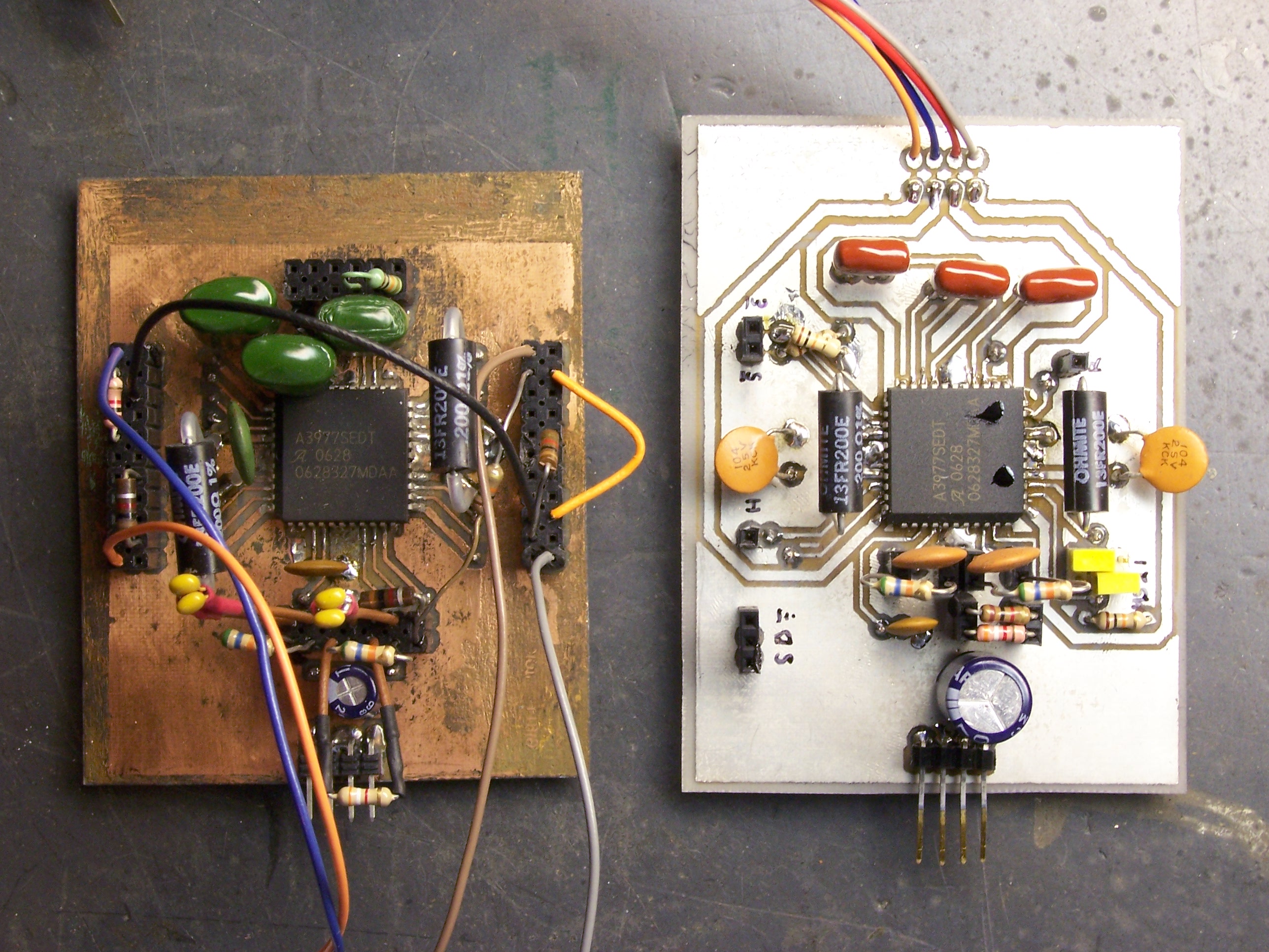
I’d been planning to build another driver board soon anyway, to drive a second axis prototype. With my first board misbehaving, I could also use the second board to help troubleshoot the first.

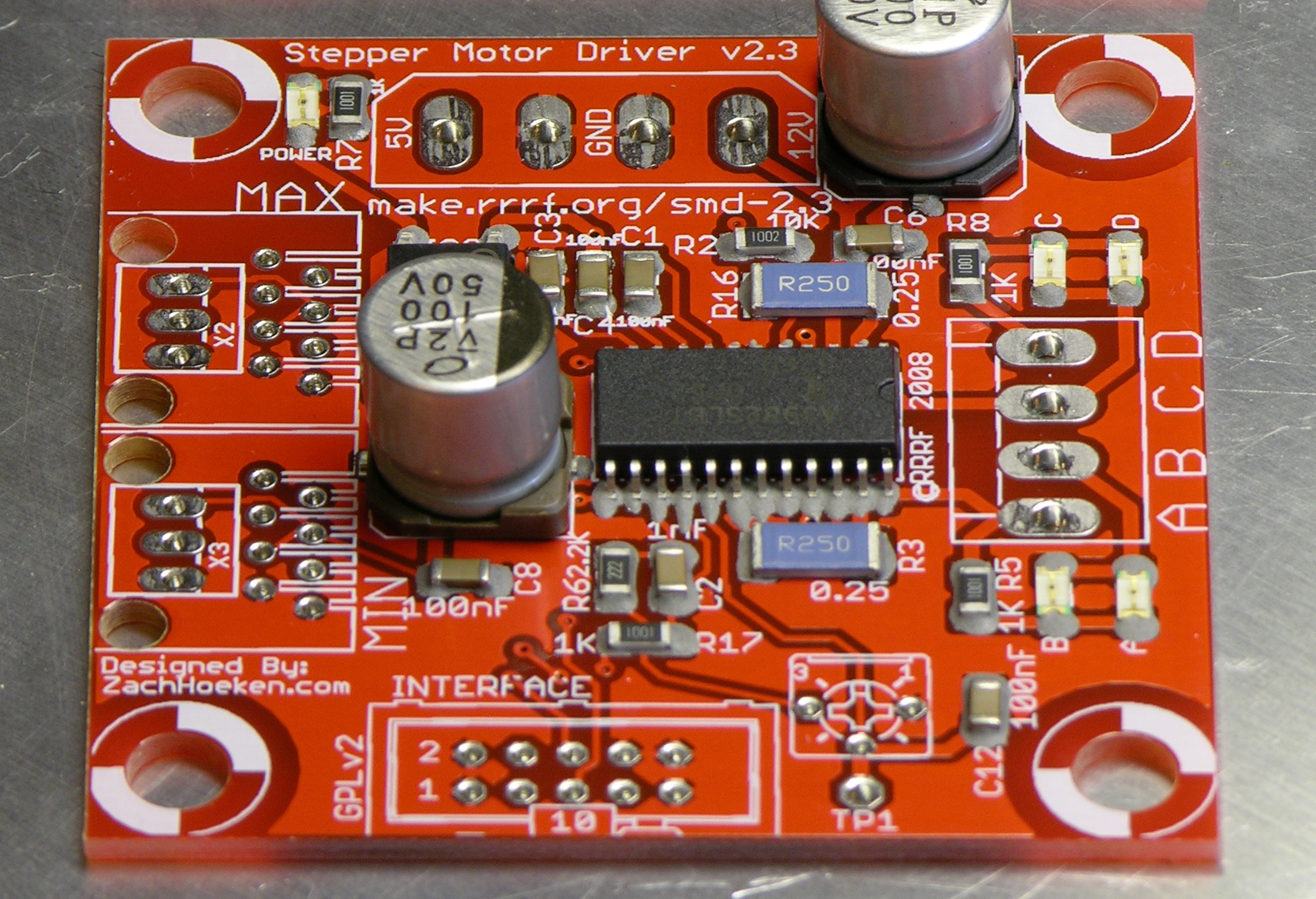
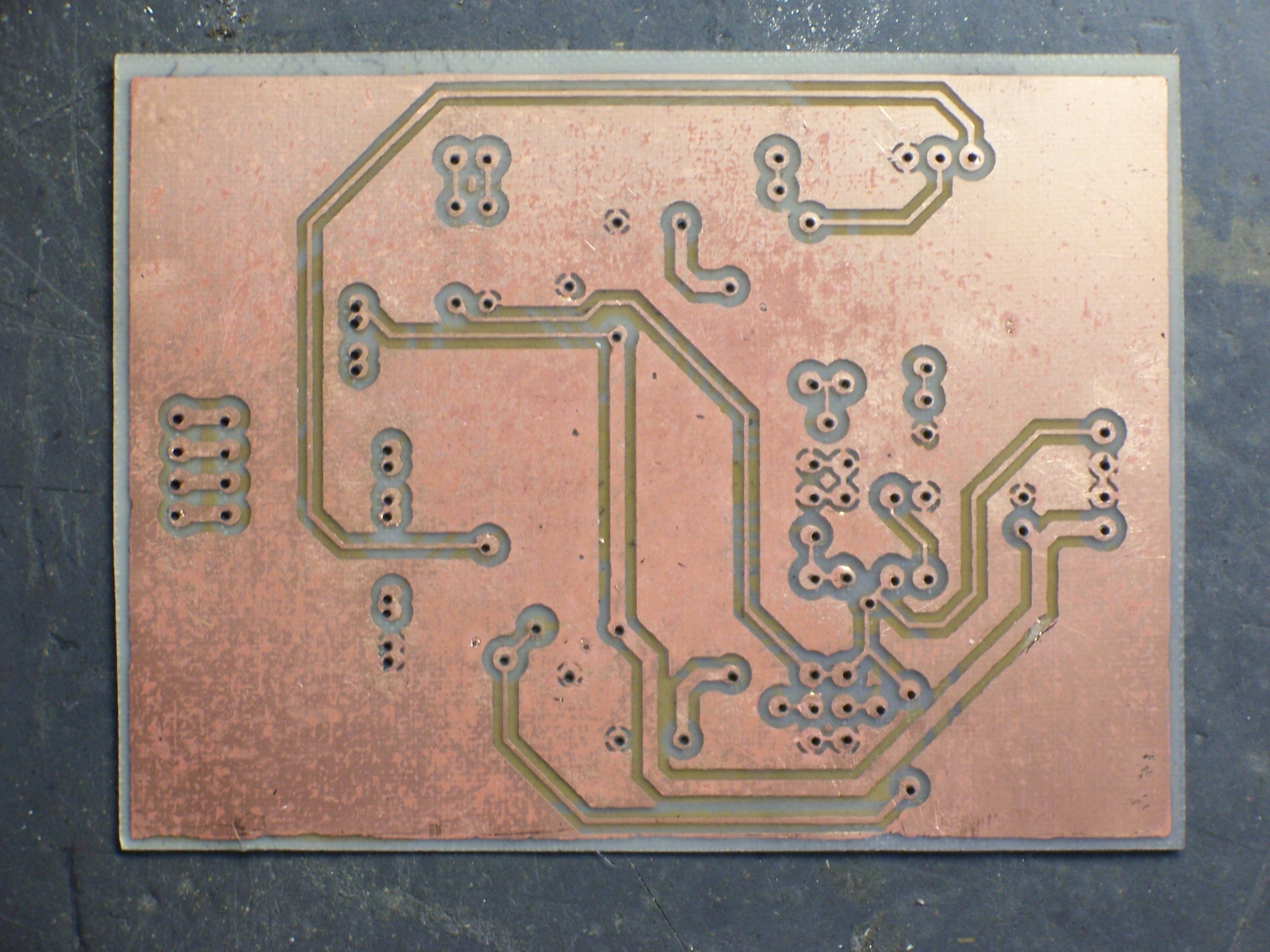
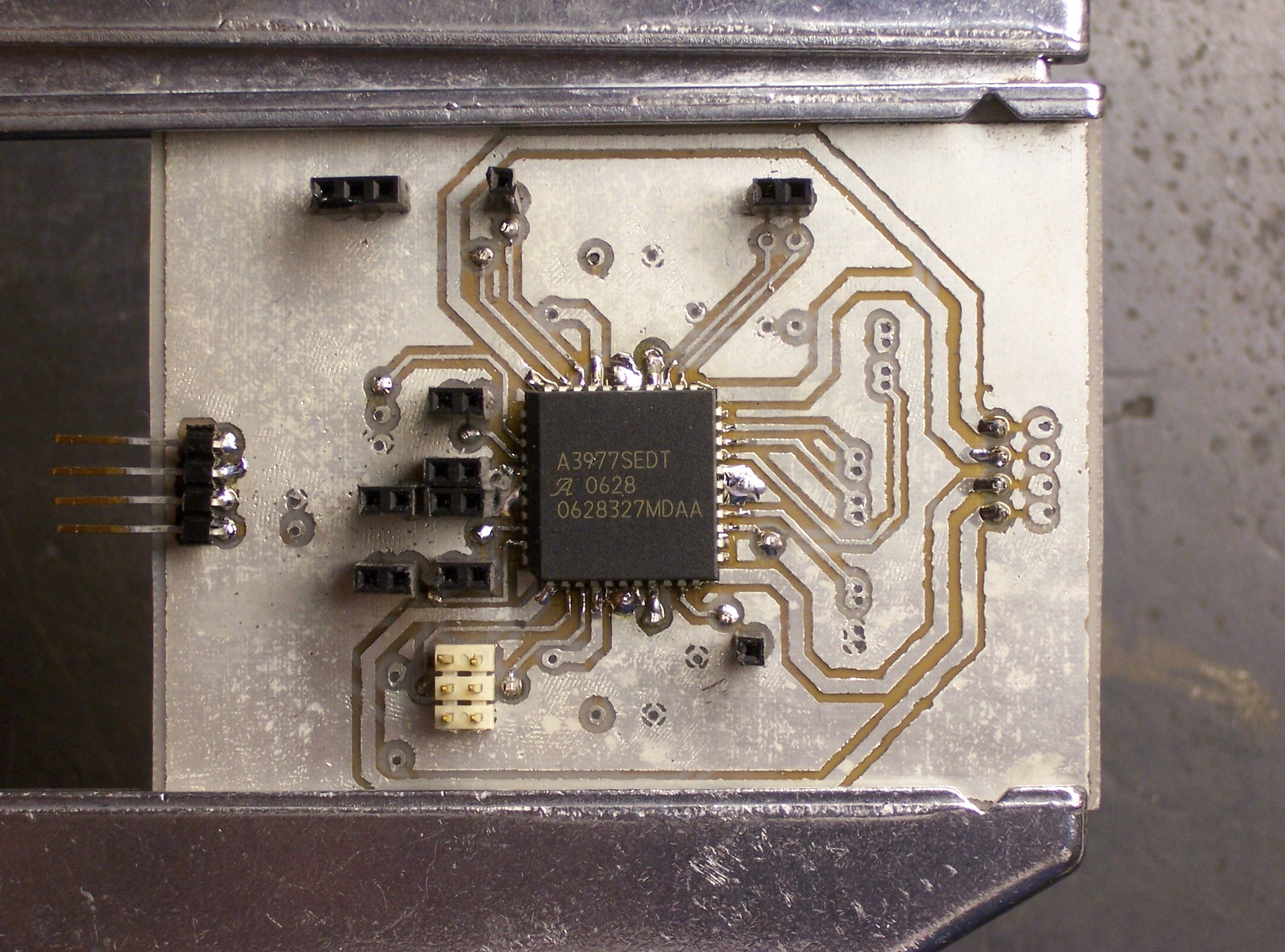
I also had a list of changes to make — things that were inconvenient about my first A3977 breakout board. I updated my layout Saturday with (among other things) nice jumpers for option settings, better grouping of signal inputs and outputs, and less reliance on having to solder leads on both top and bottom sides to carry signals through unplated vias.

Hand-Drilling and Etching the PCB

PC board stock, copper pattern, and center punch

Normally I’d use Joel’s CNC machine to drill my board, but the timing didn’t work out this weekend. Instead, to prepare for hand-drilling, I taped together two sheets of my thin double-sided board stock with a printout of the top-side copper pattern and used a center punch to mark the holes.

Alas, I was a bit overzealous with the center punch.

PC boards, holes overpunched

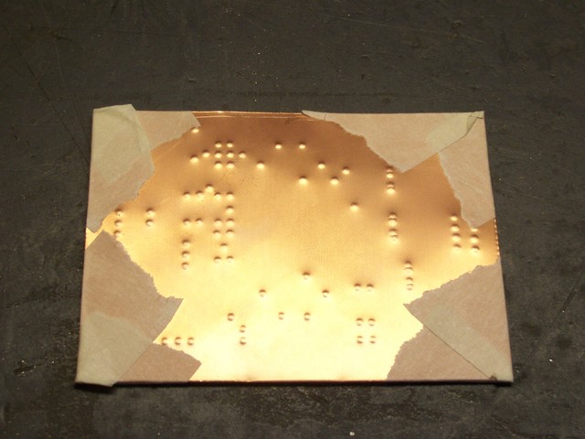
The dimples went through both boards in the stack. Yeah, thin board stock.

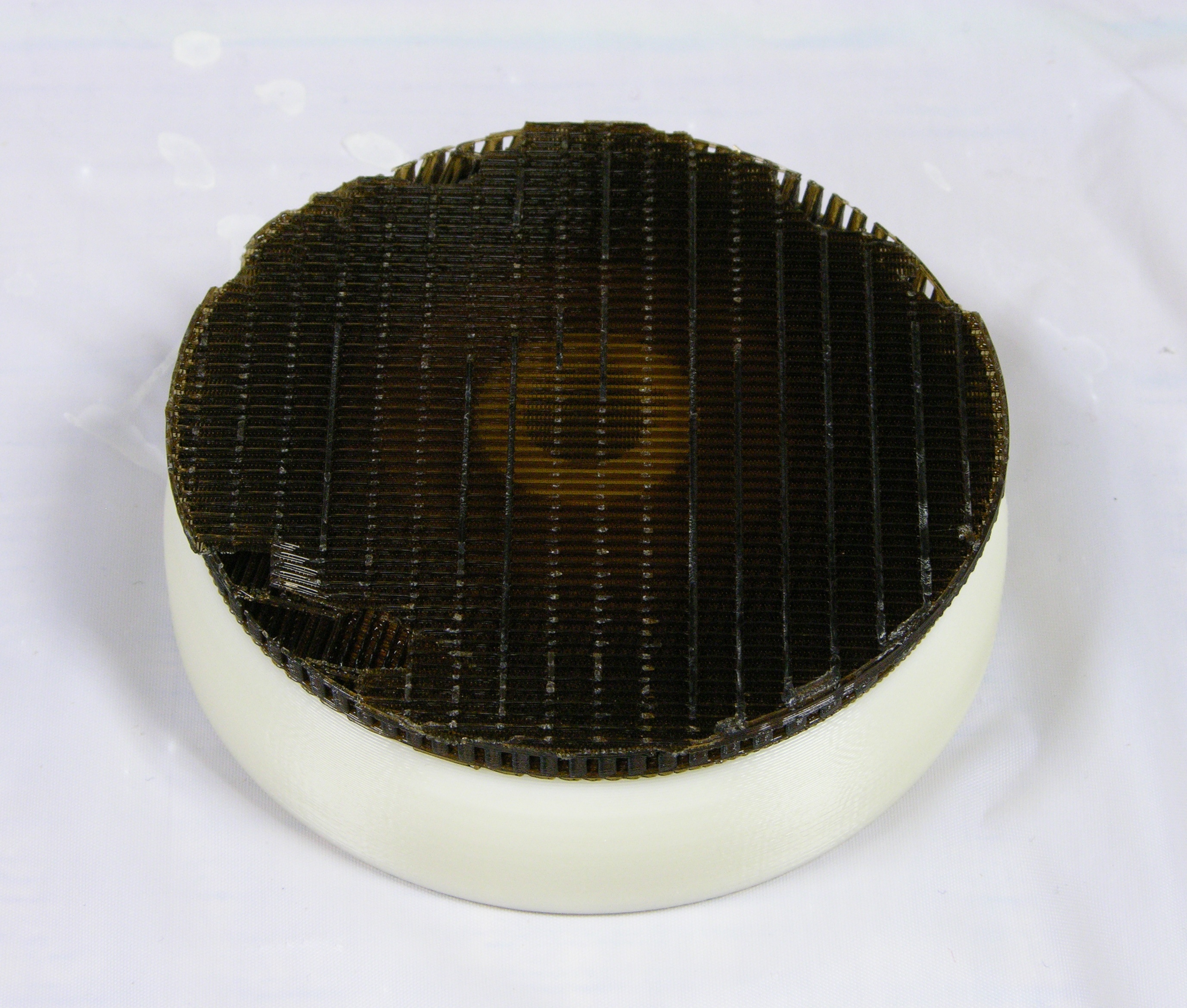
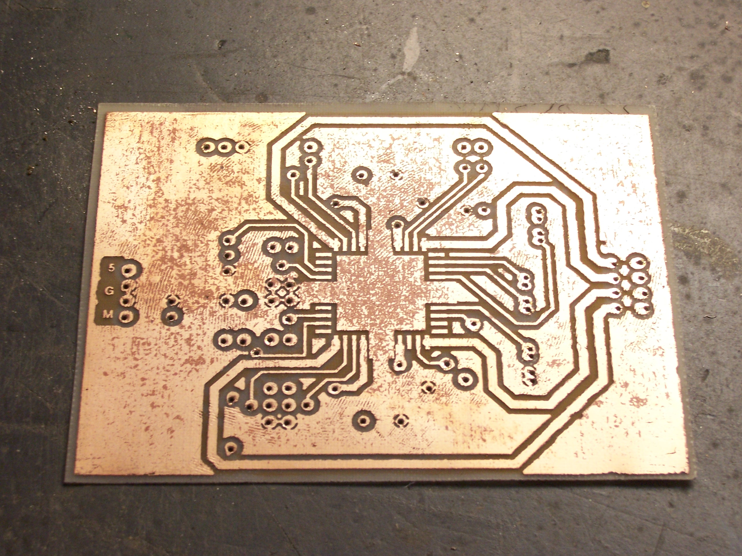
I drilled the holes carefully with a #71 bit, then used a hammer to flatten the dimples on the anvil surface of my bench vise. Apparently I did a good enough job, because I made a nearly flawless two-sided iron-on transfer on glossy paper (not even bothering with Press ‘n’ Peel Blue), using the paper towel between the iron and the board again to distribute the pressure.

Etched PC board

The board came out as nicely as any I’ve done. I used 16 mil traces and 40 mil isolation, so it wasn’t particularly challenging. Still, it etched very cleanly.

Etched PC board with pockmarks

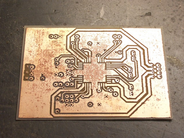
I did have a little trouble with pockmarks in some of the large copper areas. They don’t impact the performance — just the appearance. I could perhaps have sanded and polished the board to make it prettier; maybe next time.

Tinnit

On each of the last two PC boards I made, after partially populating the board, I really wished I had tried using the Tinnit. And I’m making more boards now — I know I’ll make at least one more stepper driver board (for the third axis), and probably lots of other things, in the next six months. So it seemed like a good time to try it.

The instructions say to mix the Tinnit powder package with 12 oz of hot water, then add enough water to make a pint. To plate a board, heat the solution to 120-140°F in a pyrex container, then dunk the board for 35-40 minutes, agitating every five. Store the leftover solution in a metal-free container.

Well, my package had two smaller powder packets in it, and it wasn’t clear whether that was two doses or two parts of a single dose. Nor could I find any help online. I took a chance and poured in both packets; and when the second packet caused it to start foaming, it was clear that they weren’t the same and both packets were in fact required.

Tinnit solution in glass jar

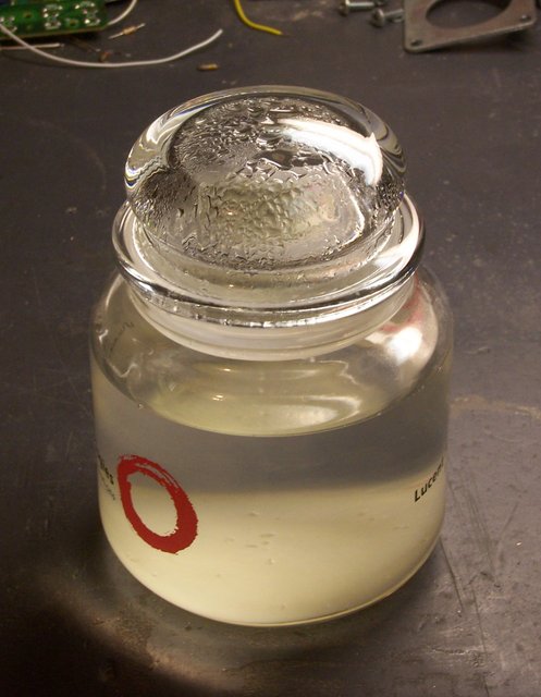
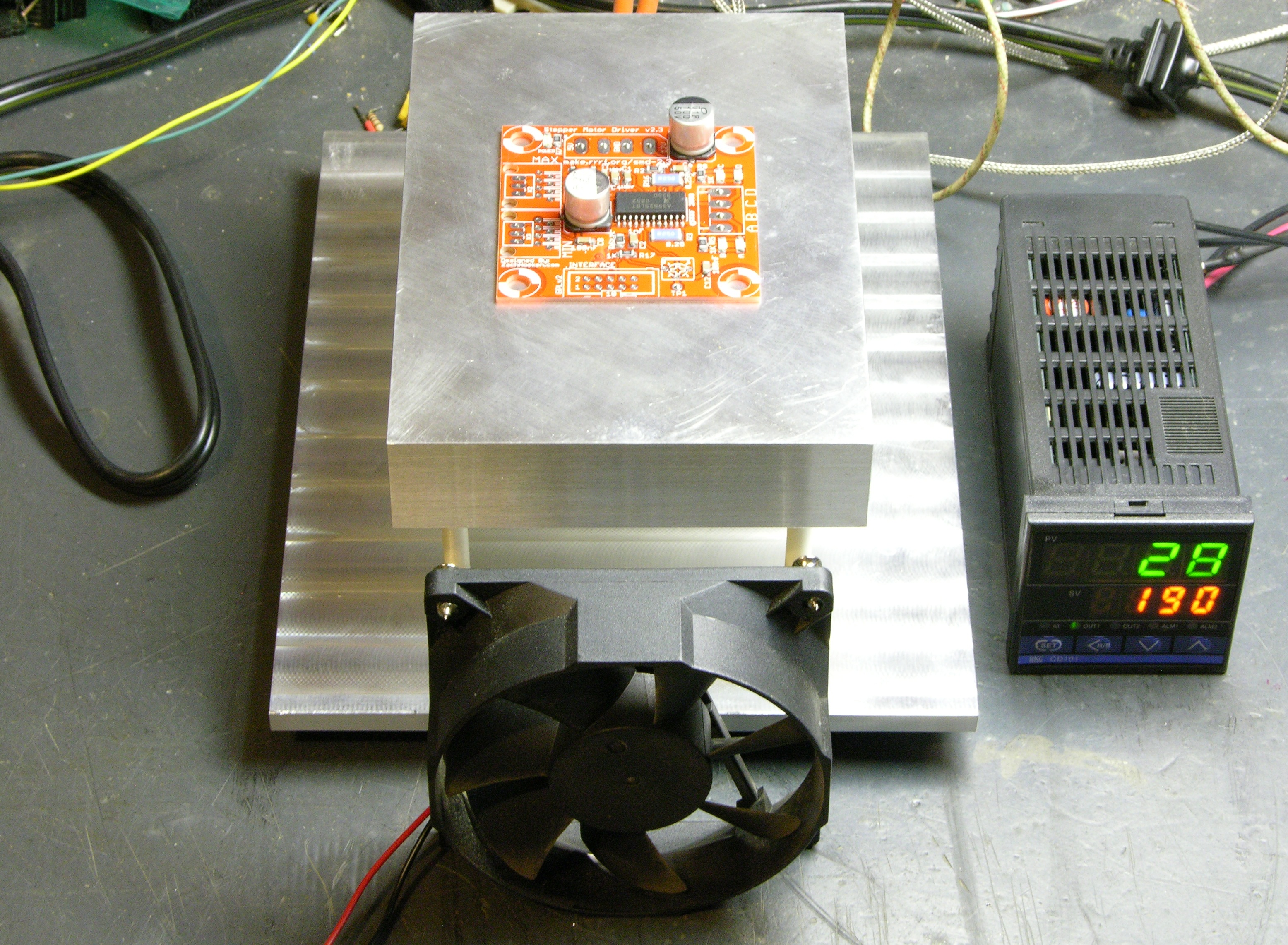
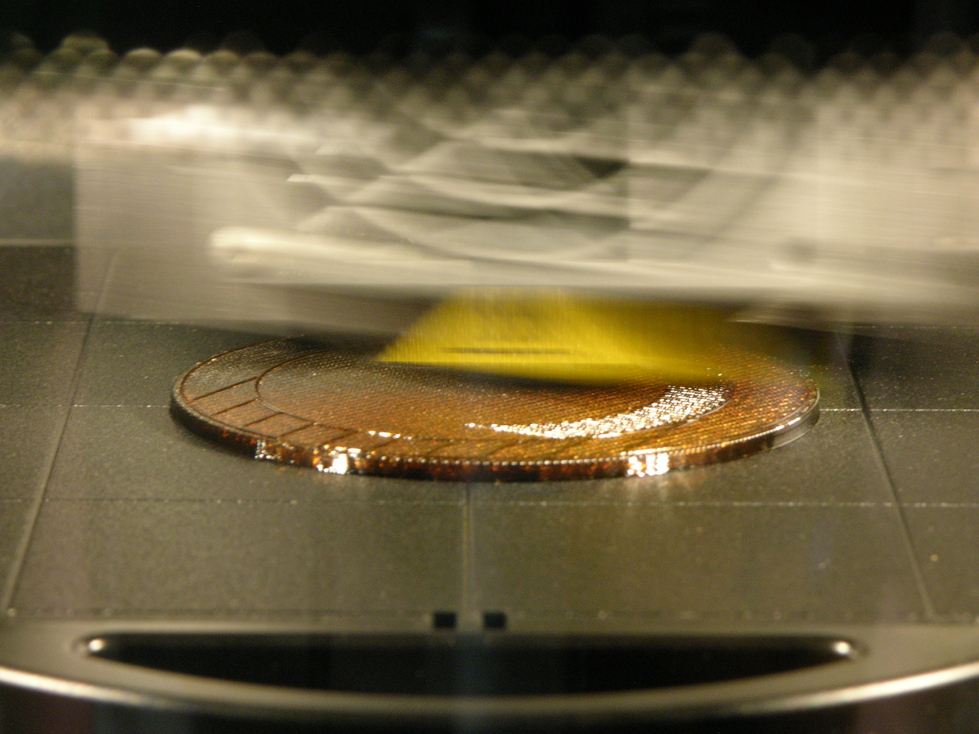
I mixed the solution in a glass candy jar that I got from a vendor about eight years ago. The jar was just big enough to dunk yesterday’s PC board, so I sidestepped a search for an appropriate separate pyrex container for heating the solution. I put the whole jar (minus the lid) onto a stove burner turned to low and checked the temperature and stirred frequently (with a plastic spoon). It’s not obvious from this picture, but there’s a flaky white precipitate at the bottom of the jar that only went fully into solution at about 130°F.

Tinned PC board

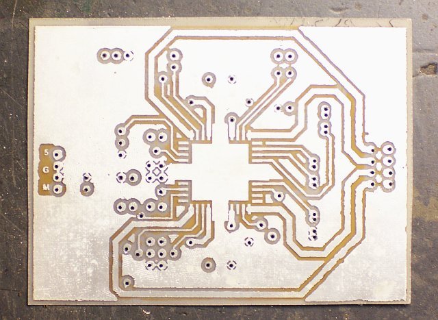
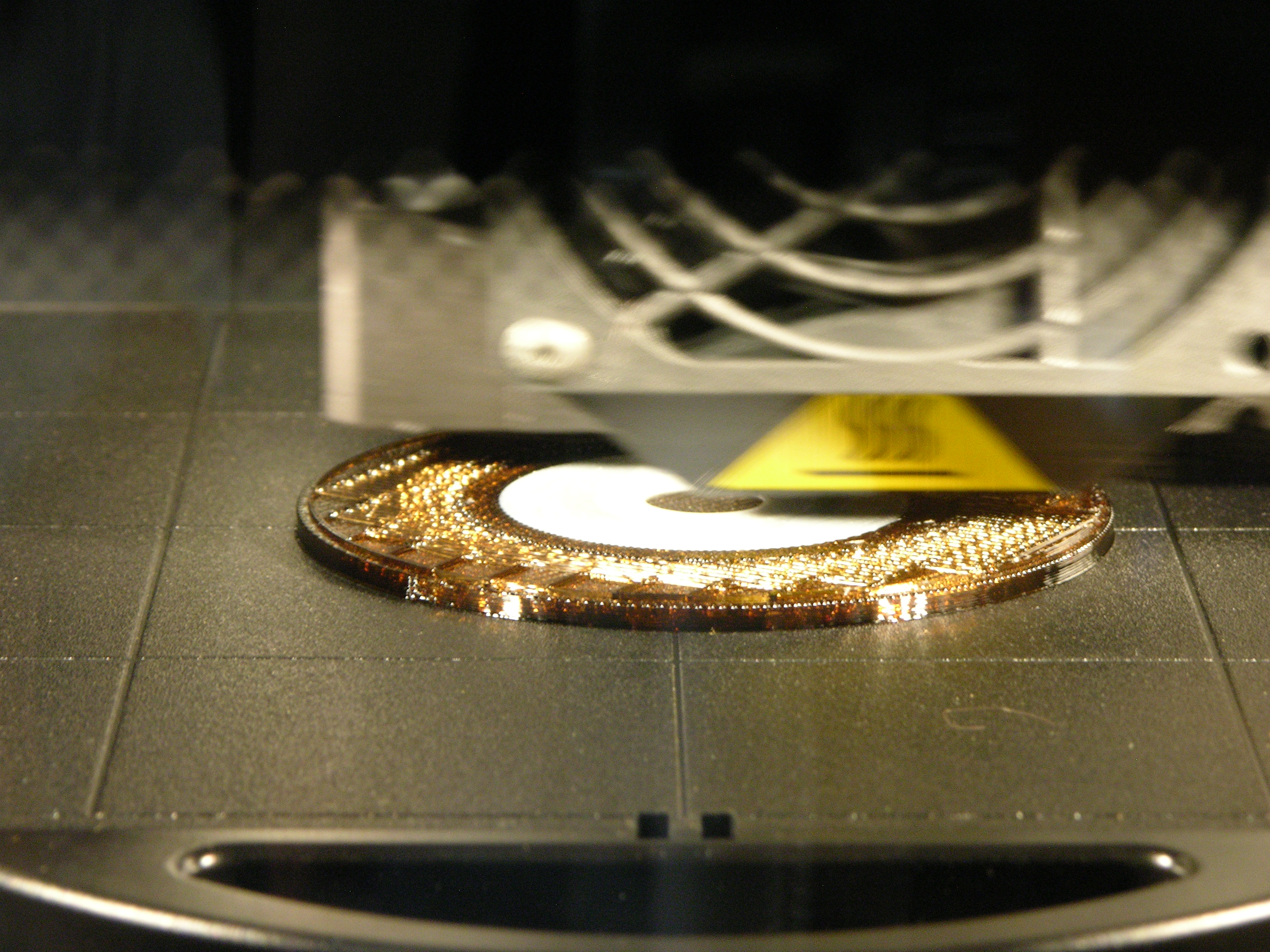
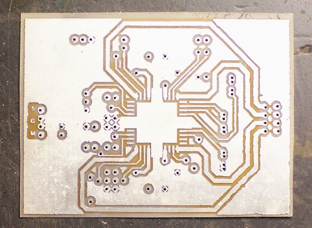
The board started turning silvery almost immediately, and coverage didn’t change visibly from about ten minutes in solution until forty minutes when I took it out. I washed and scrubbed it pretty thoroughly, and it still smells like salts.

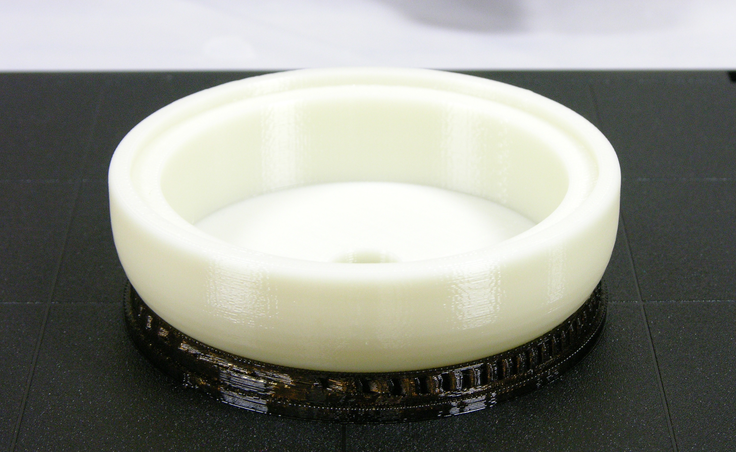
The result is very shiny and silvery. The pockmarks are still visible — Tinnit (and electroplating in general) doesn’t cover to enough depth to smooth a rough surface — but the board looks pretty good.

PLCC soldered to board

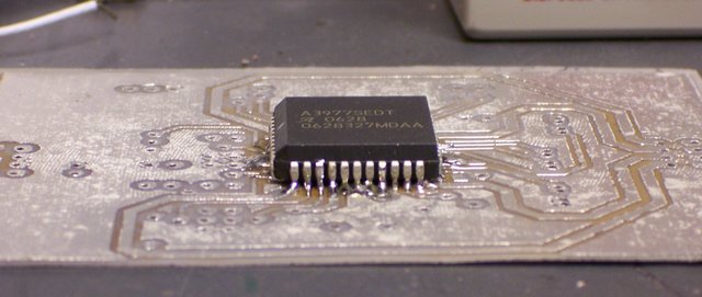
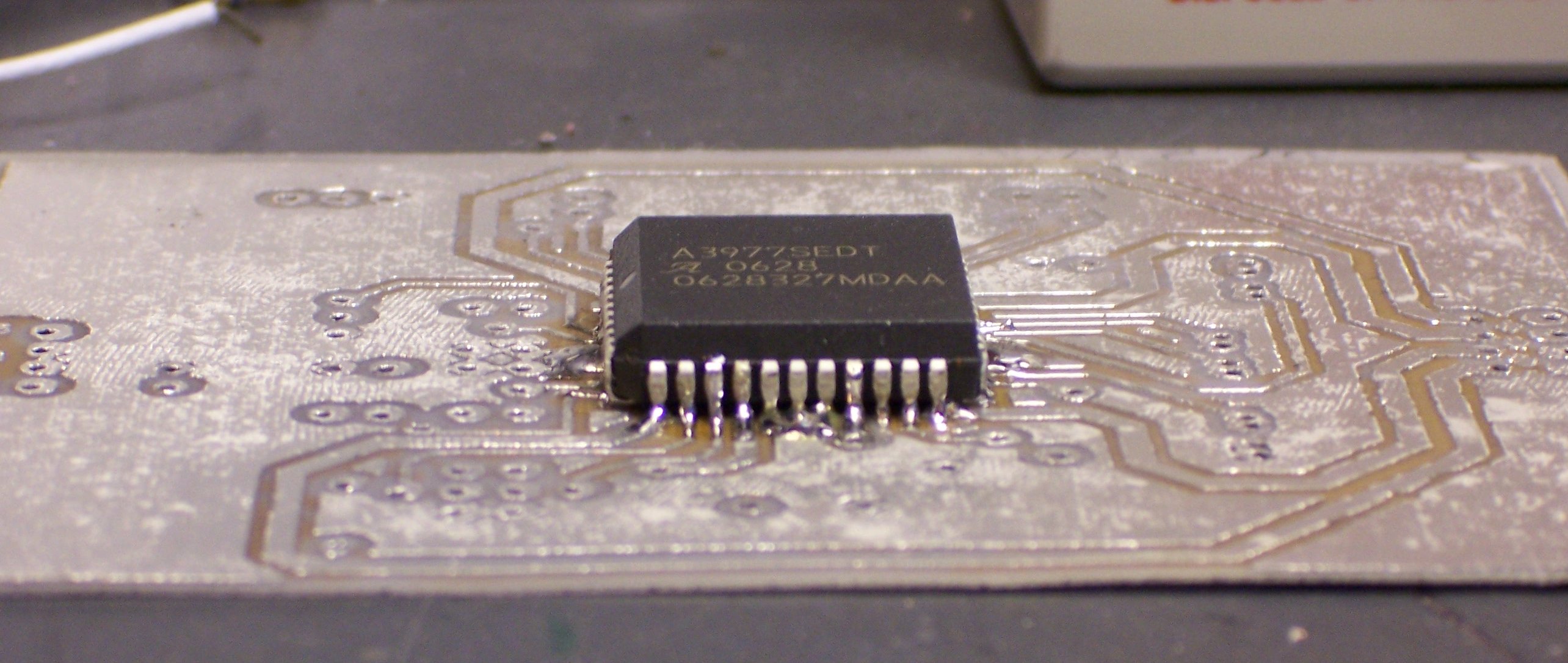
I’m particularly impressed by how much of a difference it makes in soldering. I know it’s easier to solder tinned components, but clean copper takes solder reasonably well. Still, this was amazingly easier to solder. When I built my first A3977 breakout board, I was flowing solder across multiple PLCC leads and cleaning up solder bridges; last night, I was able to solder individual leads with my SMT soldering tip.

PC board with monochromatic components

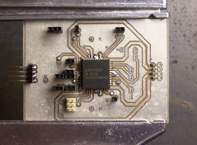
As I was stuffing jumpers and headers, I noticed how monochromatic the board was without the resistors and capacitors installed yet. I finished all the black, silver, and white components and stopped for the evening. Tonight I expect to add the passives and hopefully get the board up and running.

A3977 Stepper Driver and Higher Load Supply Voltage

Wednesday, August 15th, 2007

According to the explanation in my previous post, the Allegro A3977 stepper motor driver should be able to run motors faster with a higher load supply voltage. Naturally, I was eager to see this for myself.

Yes, yes it does.

Throwing Together an Unregulated 18V Power Supply

I’d been using my benchtop PC power supply for both 5V logic and 12V load supplies. After swapping the sense resistors this weekend and improving my step rate from 600 steps per second to about 1450, I was really curious how much of an additional improvement I’d get from a higher load supply. The 3977 is rated for a 35V load supply, but some forum posters recommend going no higher than 30V, so I was looking to try out 18-24V.

Joel just dismantled a photocopier with 20V motors; but after looking at the power supply boards, it wasn’t obvious which of the several power supplies was the one providing 20V. Plus they were switching supplies, and I don’t know whether they had integral loads or whether I’d have to provide a minimum load externally . . . bluck.

So I hacked together my own ~18V supply.

18VDC 3A unregulated power supply

From left to middle to top, that’s a brand new Radio Shack 12.6V 3A transformer, 4A bridge rectifier from a dead PC power supply, and a 18000μF capacitor out of a workhorse Accel printer from a former employer. The line cord is from a broken coffee grinder, the five-pin socket came with the capacitor and the plug from Slim, and the remaining wires and connector are from the PC power supply.

Side note: I’ve seen a few big capacitors in my day, but these impress me. When servicing these printers, I once vaporized a chunk out of my pocketknife’s screwdriver blade when I discharged the big capacitor by accident. I know personally that the last time this capacitor’s printer was powered on was no more recent than 1998. On a lark, after getting the capacitor out of the printer, I put a voltmeter across it, and it still had 3V on it. Ran an LED for a couple of minutes while I was draining it. I screwed a 1KΩ resistor across it to drain it a little faster in my power supply, so I don’t have to worry as much about hurting myself.

Power Supply Calculations

I have never kept the formulas for different rectifiers in my head, so I’ll run through the numbers for this one here. The transformer’s secondary (V2) is 12.6VAC RMS, and the peak voltage of a sine wave is RMS * √2, so the secondary peak voltage (VP2) is

VP2 = V2 * √2 = 12.6V * √2 ≈ 17.8VDC

The peak DC output of a bridge rectifier (VP) is the peak secondary voltage minus the two diode drops, so

VP = VP2 – 1.4V = 17.8V – 1.4V = 16.4V

The output of a capacitor input filter is the same as the peak DC value of its input, minus load-dependent ripple, so I should be getting about 16.4VDC out of this setup. Measured about 17.1, so I’m in range. The transformer is rated for 12.6VAC output at 3A, so it’s almost certainly putting out a little higher voltage with such a light load. If I weren’t so lazy, I’d go measure it, but that’s out of the question. :-)

And there’s no regulator. Linear regulators convert electricity into heat, and I need neither less electricity nor more heat. The A3977 is effectively a switchmode regulator for the motor coils anyway; so by regulating its input load supply voltage too carefully, I’d just be duplicating effort. Especially for a test. Note that I’m still running the logic supply voltage from the well-regulated 5.0V output of my PC power supply — the red and black wires in the photo above are picking that up and adding it into the four-pin supply jack.

With my scope across the capacitor terminals, I estimated .2V peak-to-peak ripple when running one motor at full speed. That’s pretty lousy ripple for most digital or analog circuits, but by all appearances just fine for this application. Especially, as I intend to keep pointing out, for a test. :-)

And Yes, the Motor Runs Faster

The motor is running noticeably faster before losing steps — up from 1450 steps per second to about 2300 steps per second. That’s an improvement from 2.8 seconds per inch of linear travel to 1.7 seconds per inch — a considerable difference for something as simple as changing the load supply voltage.

I want more, of course. I still want to see what happens at 24V and at 30V, so I bought a bargain 24V power supply on eBay today. When it gets here, I’ll give it a shot.

It’s worth noting that as far as I can tell, I don’t need to change anything in the A3977 circuit to adapt to the new load supply voltage. The sense resistors determine the maximum current that should flow through the motors, and the whole job of the 3977 is to keep that the same regardless of supply voltage. And I provide VREF from a divider on the logic supply voltage, so that’s also independent of load supply. Slick.