A week-long vacation without the Arduino? The horror . . . the horror . . .
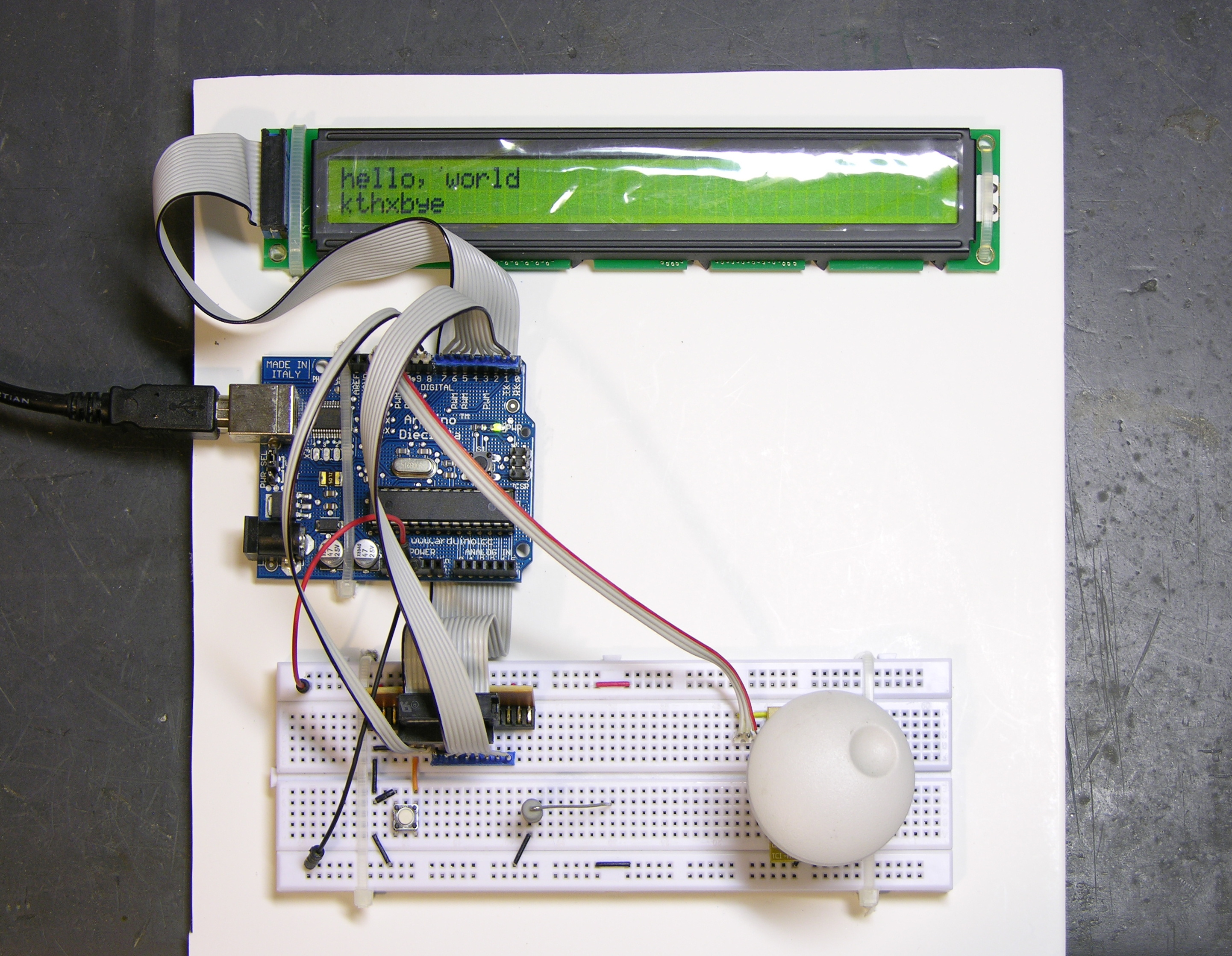
Arduino, LCD, and breadboard strapped down on foam-core sheet, for travel.
A week-long vacation without the Arduino? The horror . . . the horror . . .
Arduino, LCD, and breadboard strapped down on foam-core sheet, for travel.
I’m playing keyboards this fall in another rock concert to benefit the high school robotics team, and for some of the tunes I need to be able to fade an organ in and out over a period of a measure or two. My keyboards are velocity-sensitive, so if you hit the keys harder they play louder (like a piano); and they have aftertouch, so if you press down extra-hard on the keys you can get special effects. But there’s no good way to change the volume of their organ sounds dynamically, and these synths don’t have inputs for volume pedals.
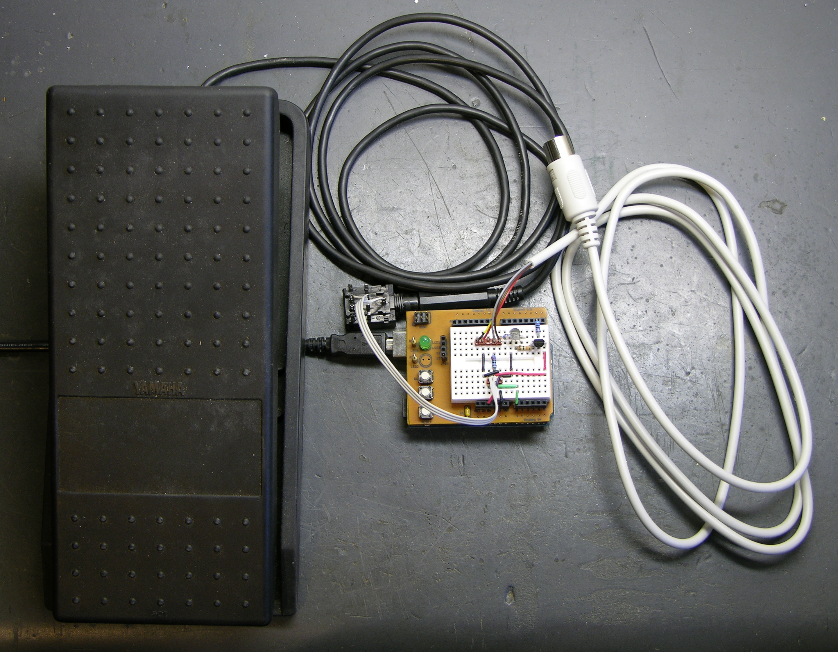
This is the MIDI volume pedal project I was starting to work on when I took apart a Baldwin organ swell pedal and decided to leave it intact based on what I found inside. I got another analog volume pedal from a pile of unknown origin at the school lab and finished the job.
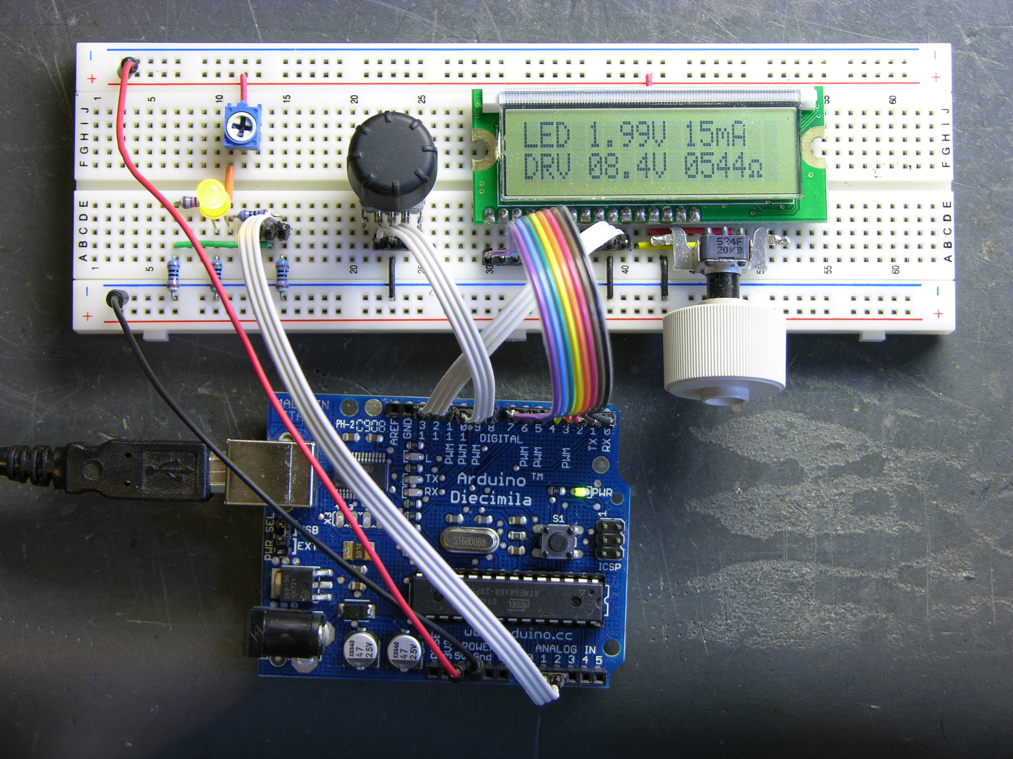
I’m still working on the LED calculator (original idea and most recent work) — I’ve finally got ’round to adding a rotary encoder to set the target system voltage. Now you can turn the potentiometer to set the LED brightness, turn the rotary encoder to set what voltage will be used in the ultimate LED circuit, and read the LED voltage, current, and current-limiting resistor values off the screen.
I also found the Ω in my LCD’s character matrix, so I tidied up the display a little.
And most significantly, I wrote an Arduino library for reading (multiple) quadrature encoders. The simple approach of polling them inside loop() was causing me to lose a lot of steps from the encoders; and the code to read them using hardware external interrupts (lower on the same page) only works on digital pins 2 and 3, so only supports one encoder if both pins are wired to interrupts for the highest resolution, or two if interrupting on a single pin and polling the other.
My Quadrature library uses the TIMER2 overflow interrupt service routine to poll multiple encoders rapidly and track the results, supporting as many encoders as you have room for on the digital pins. It also encapsulates all the dirty work into the library code, so using it is as simple as
#include "Quadrature.h"

Quadrature myencoder1(9, 10);  //  Connected to pins 9 and 10

loop() {
  x = myencoder1.position();
}
It still has some rough edges and it’s by no means perfect (more on that below), but it sure makes it easy to use rotary quadrature encoders. It’s available on a new Downloads page for anyone interested.

I’ve been saving these relics of the Information Age forever, initially because I had the computers to go with them, then out of nostalgia, then because I forgot I had them, and now because it seems like the boxes should be useful. But really, I’d just like them to go away.
Anybody want some three-ring binders with matching boxes, maybe to put an Arduino and breadboard in to take with you on vacation and play with circuits when you’re stuck in Saint-Tropez for a couple of weeks with nothing to do? The rings oughtta be good for holding baggies of parts, or something.
Seriously, if anyone wants any of these, they’re yours for the cost of shipping. The MS-DOS Operating System is missing one of the two volumes from the double-wide case; the Wordstar and Operating Instructions are intact in single-wides.
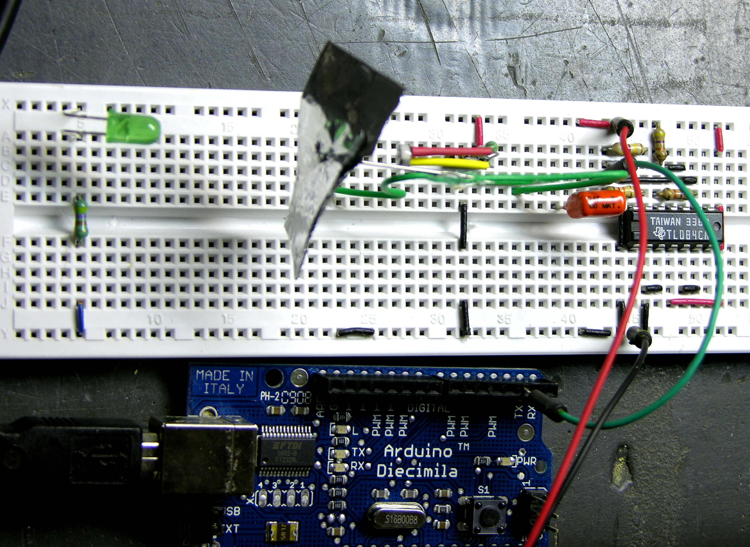
In part 1, I described making a propeller out of foil to measure the airflow of my air conditioning system, building an optointerruptor from an LED and a CdS photocell, and amplifying the signal to a usable level.
Next, I needed to feed the signal into a digital input on the Arduino. Old-school digital inputs don’t like having analog signals fed into them; but I knew from working with a PIC that some of the Arduino/ATmega pins would probably have Schmitt-trigger inputs, which have hysteresis.
A digital input with hysteresis turns on when the analog input becomes higher than an upper threshold but doesn’t turn off until the signal falls below a lower threshold. The effect is that an analog signal wandering back and forth around the midpoint doesn’t cause lots of twitching back and forth of the digital interpretation. Regular thermostats work this way — they turn on your AC when the temperature gets one-half to one degree above the thermostat set point, and turn off the AC when the temperature falls one-half to one degree below.
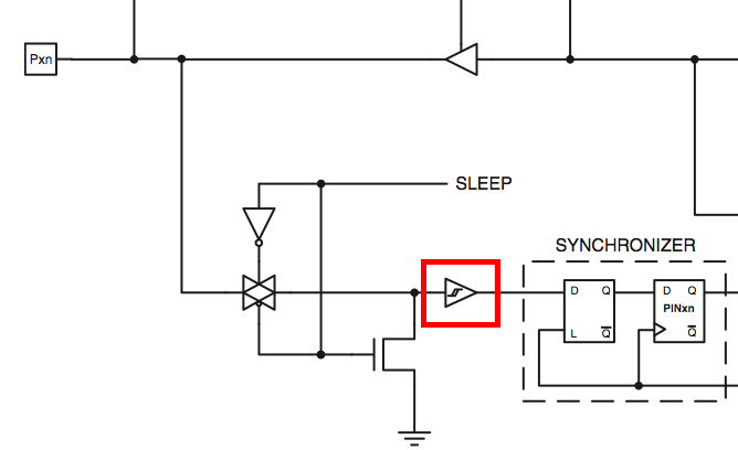
So imagine my delight to find that every ATmega8/168 input pin has Schmitt-triggering. Any pin would do! But I had two particular ones in mind . . .
All I wanted the program to do was count how fast the propeller blade went by, activate a relay when it got above a higher speed, and deactivate the relay when it got below a lower speed (hysteresis again, at a different layer of the system). For a program that simple, I could write a loop to watch the input pin in software . . . but why, when the ATmega can do it in hardware?
Necessity is said to be the mother of invention, and 90+°F daily temperatures with the air conditioner on the fritz made me feel pretty inventive.
Our air conditioner was low on refrigerant and the blower fan motor may be running slower than spec and not moving enough air. Between the two problems, the expansion coil inside the furnace housing would ice up, over a few hours completely blocking the airflow and preventing any meaningful heat exchange. I’d then have to switch off cooling mode and run only the fan for a few hours to melt the ice.
On a weekend when I was home all day, I discovered that I could keep the house fairly cool by setting the blower fan to run all the time, manually monitoring the airflow out the vents, and cycling the AC off when airflow was restricted and back on when it opened up. Which sounded like a perfect job for a microcontroller.
Introducing the scungy anemometer, or Airduino v0.1, for short. Also introducing real-life code using the Arduino’s external interrupt pin(s).
Cort and I are good friends and both interested in electronics, but have had surprisingly little opportunity to work on electronics together. He’s an amateur radio operator and very much into RF design, and I’m more interested in physical computing.
So when he started describing his receiver voter project and suggesting that I might be able to help out on some of the digital interfacing, I jumped at the opportunity. A radio repeater receives transmissions at one frequency and rebroadcasts them at a nearby frequency, effectively boosting the signal (by repeating it) without increasing transmission power over the legal limit.
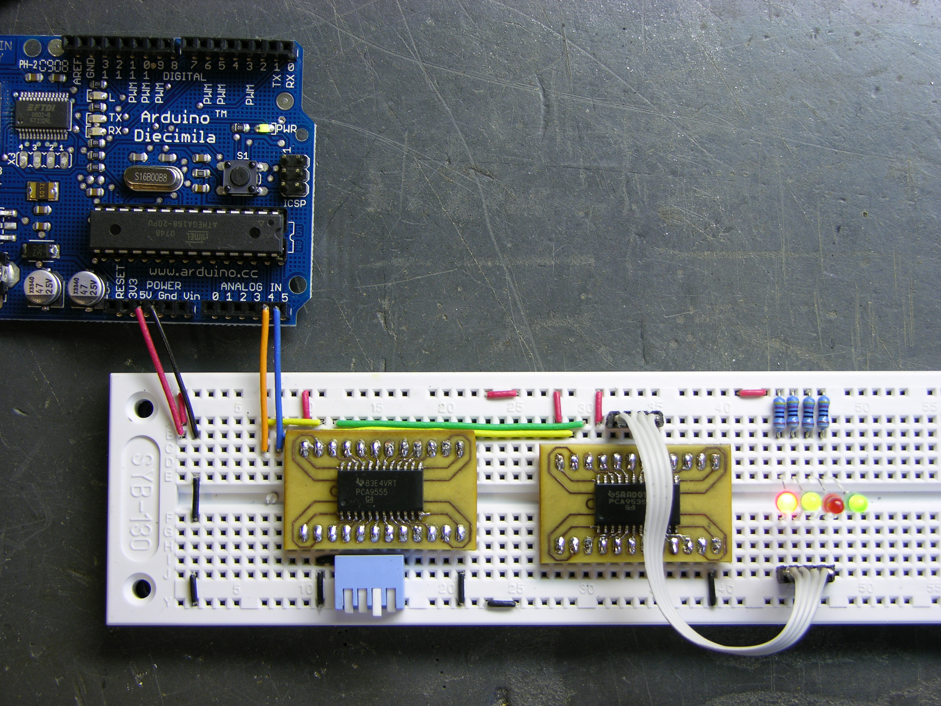
The voter picks the best signal from several different receivers (possibly several miles apart, linked back to the repeater base) and routes it to the repeater. And Cort’s voter will have lots of pushbuttons, LEDs, and digital controls — more than he could wire directly to the Arduino he’s planning to use to control it.
That’s where I come in. Cort is very interested in learning the Arduino, but he hasn’t done much with microcontrollers lately and is to some extent playing catch-up with a decade’s worth of advances in technology. So I’ll pitch in and give him some ideas and programming assistance on the digital I/O.
I started by looking for digital I/O expansion chips, and I did not start by looking for I2C. I’ve never worked with I2C before and I thought I’d find something with SPI, but oh no, that was not to be the case. Nearly everything I could find — and everything I could find that was readily available and affordable — used I2C. This is actually a good thing — I2C uses only two interface pins to talk to up to 127 devices, and SPI needs two pins for the bus plus a separate chip select line for each device — but it wasn’t what I was hoping for when I started looking.
So I ordered some samples, warmed up by trying to interface to an I2C EEPROM I had lying around (with no luck whatsoever, although I now know several things I did wrong and will go back to it soon), built some breakout boards, and got I2C communications up and running on the Arduino this weekend.
And the number of mistakes I made along the way was staggering. Not just little misunderstandings, but mind-numbing stupid mistake after stupid mistake, things I’ve know better since I was six. With a weekend like this, it’s a wonder I haven’t run over myself with my own car somehow.
So do what I say, not what I did.
First off, I had to get the Arduino talking to I2C. There’s not much online about doing I2C on the Arduino, and the most useful for me was Julian Bleecker’s blog post prosaically entitled Arduino and the Two-Wire Interface (TWI/I2C) Including A Short Didactic Parenthetical On Making TWI Work On An Arduino Mini.
It turns out there’s a Wiring library called Wire (why not, oh, say, I2C???) that operates the ATmega’s hardware I2C port and which has been incorporated into the Arduino software since version 6, so everything I needed was right there; I just had to figure out how to hook it together.
Between the Wire documentation being sketchy and not explaining how each function corresponds to an I2C function, its code examples being outdated and occasionally incorrect, my lack of familiarity with I2C in general, my not yet having a working I2C circuit to reference, and of course my many, many mistakes, this made for a bit of a vexing experience.
Let’s do it.
An Arduino “shield” is a PC board made to plug into the top of the Arduino, covering it (hence the name) and extending the Arduino signals to provide some extra functionality. Shields I know about are prototyping shields (“protoshields”), with a tiny breadboard on top; motor control, with H-bridge drivers to run motors, servos, and steppers; and ethernet, with a Lantronix Xport ethernet interface onboard. (I know there are shields from places other than Adafruit, but I really like supporting Lady Ada’s open-source hardware lifestyle, so I tend to look there first.)
After getting my Arduino, I had thought about getting a protoshield, but dismissed it pretty quickly — it seemed to me that the tiny breadboard on it would be too small to be useful for anything complex enough to be worth using the Arduino for. But Friday the Arduinos arrived for class, I agreed to do a demo/intro on Monday, and I realized it’d be a lot easier to do on a protoshield than on a separate breadboard.
With no time to order one before Monday, I had to construct my own over the weekend. I started with Lady Ada’s EAGLE schematic and board files (Creative Commons 2.5 Attribution Share Alike) and hacked them up for a single-sided board that I could etch quickly and easily. I took out her solder prototyping area, moved headers to align better with my tiny breadboard, changed up the LEDs and pushbuttons, and generally did enough work that I’m not sure I saved any time starting with an existing design. ![]()
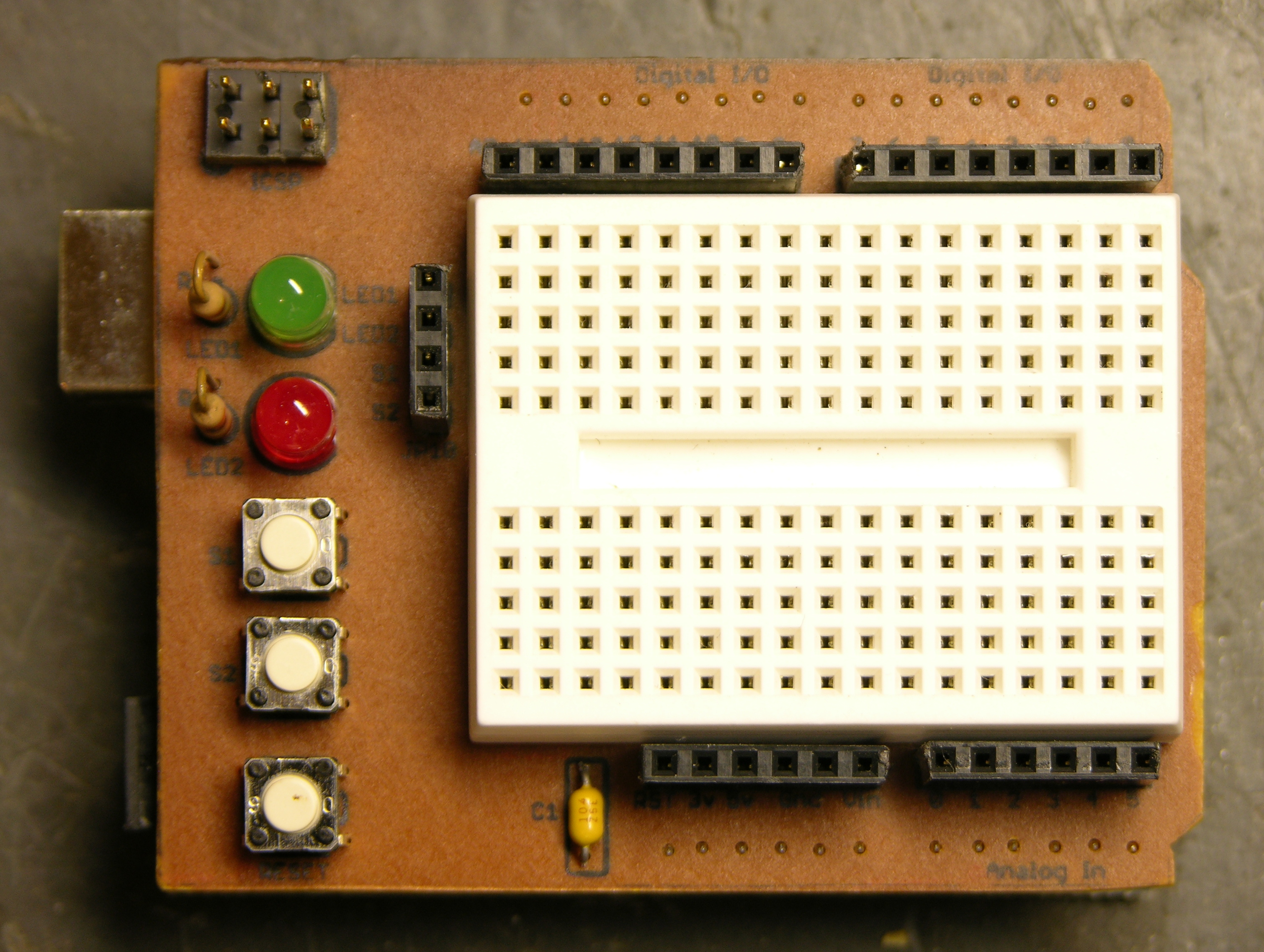
Here’s the result — ugly but very functional. I generally use breadboard wires cut and bent to length, so it matters to me that the header sockets are aligned with the breadboard columns and spaced a multiple of .1″ away. It works out very nicely.
Worth noting is that I used Cort’s idea of iron-on toner transfer for the silkscreen layer on the top side of the board.
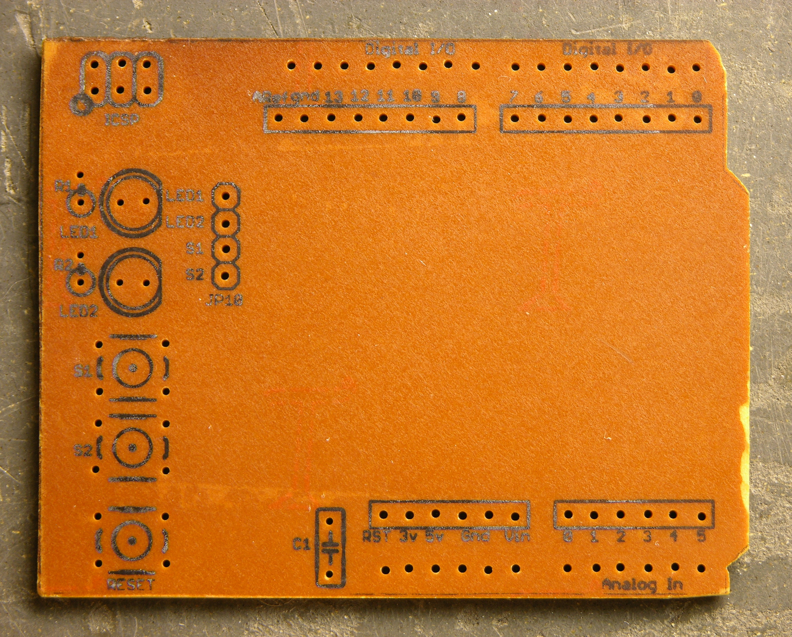
After the copper is etched, the etch resist cleaned, the board tinned if you’re tinning, and the holes drilled, you print the silkscreen layer and do an iron-on toner transfer just like you would for etch resist. The main difference is that for appearance’s sake, you really want to get all the paper fibers scrubbed off of the toner — I probably spent half an hour in the sink with the toothbrush getting it clean.
I think the method is great; it’s just this instance that’s less than perfect. For one, this PCB is very dark, and the black toner doesn’t show up well; it’s much more readable on lighter boards. For another, the font is really smaller than is advisable for a toner transfer — I’m surprised it actually worked as well as it did.
It’s a very nice change to have labeled connections on a homebrew PCB.
I practiced my spiel tonight for class tomorrow, starting with the Arduino “Blink” sketch flashing the onboard LED, then:
pulse() function that uses analogWrite() (PWM output on pins 9-11) to fade an RGB color from dark to bright to dark and updating the sketch to pulse red-green-blue-red, etc.It’s all pretty easy stuff, so the idea is that I’ll be able to do it while maintaining a stream of patter. We’ll see how that works out. ![]() Still, it’s a nice introduction to a few of the capabilities of the Arduino and to how easy it is to just try things when you have a breadboard and a nice microcontroller development system.
Still, it’s a nice introduction to a few of the capabilities of the Arduino and to how easy it is to just try things when you have a breadboard and a nice microcontroller development system.
Using the protoshield tonight has convinced me that it’s great for a tiny demo, and too small to be useful for real work. ![]() I’m not complaining, though; it’ll be fun to have around.
I’m not complaining, though; it’ll be fun to have around.
One thing that would help is the addition of a ground bus at the bottom — I waste a lot of column space leapfrogging ground to everywhere I need it. There’s room on my board that I’ll add a ground row on V2.
Original shield design by Lady Ada
Tiny breadboards from terminalcity
I still want to find a small LCD module for the LED calculator, so I can fit the whole thing into a box with a footprint about the size of a deck of cards. But for prototyping, I have a stack of 2×16 LCD modules about 3 1/2″ wide (viewable about 2 1/2″) from Slim, and Wednesday night I got one hooked up and working.
They’re Optrex DMC-16207 modules, and they seem to be using the Hitachi chipset that everyone uses, or at least an equivalent, although I didn’t know that at the time. Searching online, I had a hard time finding data on this exact module, but came across a mechanical drawing, a module user’s manual, and finally a full datasheet.
I dived in and wrote my own LCD interfacing code. I found out in retrospect that there are several other Arduino LCD interfacing projects out there:
But all of them are using hard-coded delays to pause while the LCD processes commands, rather than checking the busy flag. To be sure, I’m doing the same thing right now in my first draft of the code; but I’m going to go back and clean it up to do it right.
Also, I haven’t checked all of them, but at least one is using digitalWrite() to manipulate each bit of the port register individually. Since I’m dedicating eight Arduino lines to the LCD’s I/O port, I can write the port register as a byte rather than twiddling individual bits, saving time and effort.
My goal will be to write a nice library module/class that encompasses these different approaches (8-wire vs 4-wire, busy flag vs hard-coded delays, read/write interaction vs hardwired write-only) and presents a clean interface to the programmer to select the options. Of course, for now, I just wanted to get it up and running.
I found this ATmega to Arduino pin mapping, which confirmed that Arduino digital lines 0-7 are PORTD lines 0-7. And the Arduino port register reference shows that DDRX and PORTX are defined as Arduino variables; so writing to a port is as easy as PORTD = $ff . It’s very nice that they left those low-level features exposed, even though in most cases it’s better to use the higher-level interface for portability.
So here’s the work in progress.
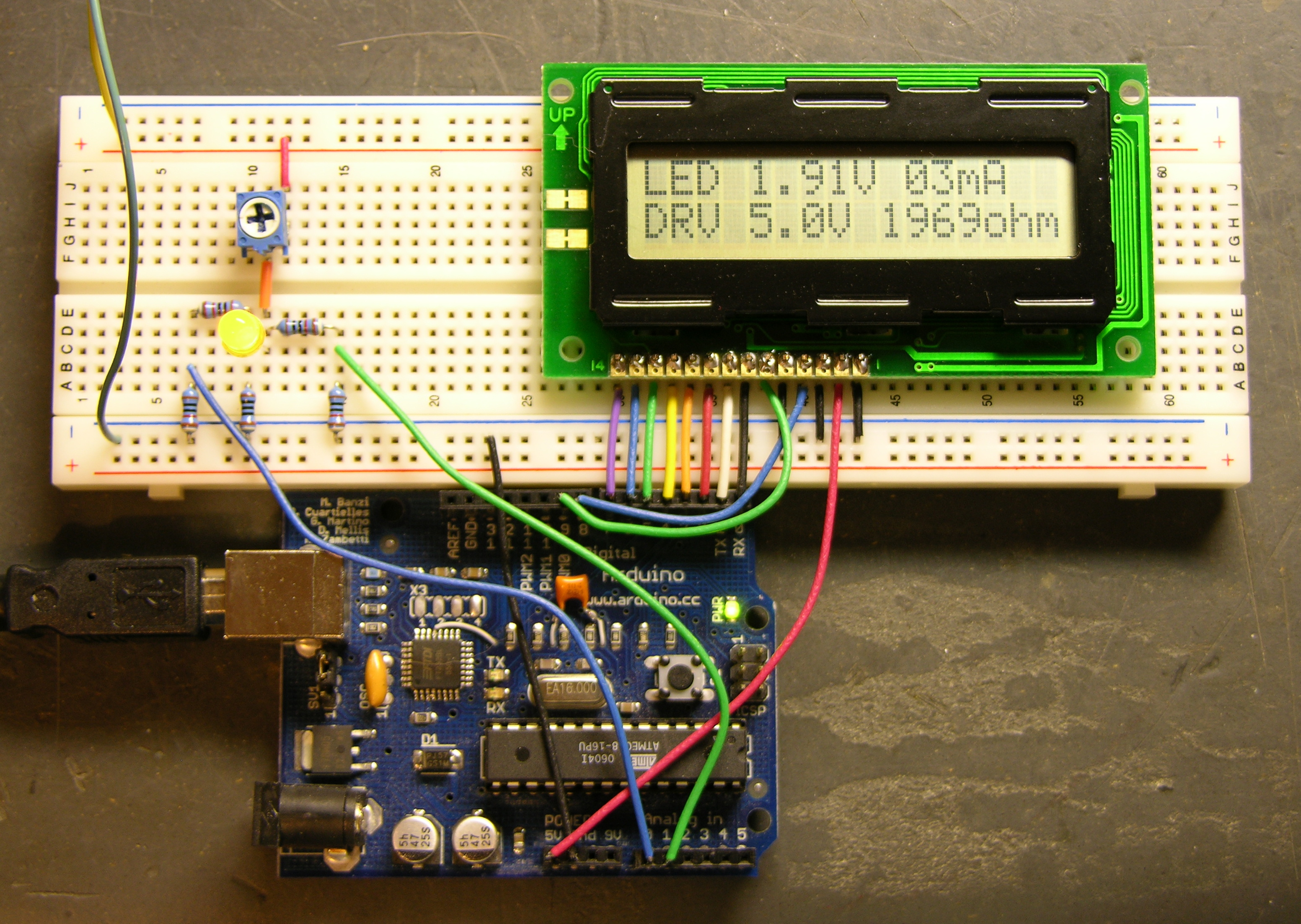
The Arduino is getting power from USB and supplying 5V power to the LCD. The LCD contrast is hard-wired to ground. Although it actually looks pretty good right now, I’ll want to put in a potentiometer to adjust contrast. And I’m still using my bench power supply to run the LED circuit at 9V.
I don’t have a method built to select the voltage of the target circuit — the software is assuming 5V for now. The easy thing to do would be pushbuttons to bump the desired voltage up and down. It’d be kind of fun to do it with a spinny-wheel, although I’m not sure how much that would increase the cost, and I’m concerned about overengineering this thing if I really want to offer it as a kit. Maybe another potentiometer is a good compromise.
However the target voltage is selected, I need to determine the selectable range (which could of course be overridden by an owner with an AVR programmer). I’m thinking 3 – 15V in .1V increments. Is that enough?
Older Arduino boards like mine have two annoyances associated with uploading software to them. First, you have to press the reset button (physically) to trigger the bootloader to expect new software from the host computer. Second, the Arduino waits allegedly 6-8 seconds (actually about 10 on mine) on every boot before starting your program, in case you might want to be uploading new software to it.
Small annoyances, to be sure, but they add up quickly when you’re trying to tweak a timing constant in a program and uploading software repeatedly. Thus in designing the latest Arduino, the Diecimila, the team addressed these two issues.
On the Diecimila board, they added a capacitor between the USB-serial chip’s DTR line (active-low) and the microcontroller’s reset line, so that the host computer can trigger DTR and pull down the reset for a moment, relieving you of pressing the button. In the new version (10) of the IDE, they added code to support that new functionality. And in the bootloader burned into the ATmega168 microcontroller, they shortened the boot wait time to a second or less.
All of that comes prepackaged for Diecimila owners; but owners of older Arduinos are resourceful and found how to adapt their own boards as well. The NG can be hacked by soldering a capacitor across two adjacent pads that appear to have been put there for that purpose. The Arduino serial can be hacked by stringing a capacitor between the serial connector and the reset line.
But I have an Arduino USB, the first version to support USB and not yet a “next generation,” and I haven’t been able to find instructions on modifying it. It doesn’t have the pads already broken out like the NG; in fact, it doesn’t even have the same package USB-serial chip. So I muddled through, found the right pins, and did it myself. Works (mostly) great!
The page for the NG hack simply shows you physically where to put the capacitor on the NG board and doesn’t describe what it’s connecting electrically, which didn’t help me, as I needed to figure out where to put it on the physically different USB board. Fortunately, the page for the Arduino serial hack gives the critical information:
The retrofitting process consists on soldering a 0.1uF disc capacitor between the DTR pin [of the serial port or USB-serial chip] and the Reset signal [of the microcontroller].
Good enough!
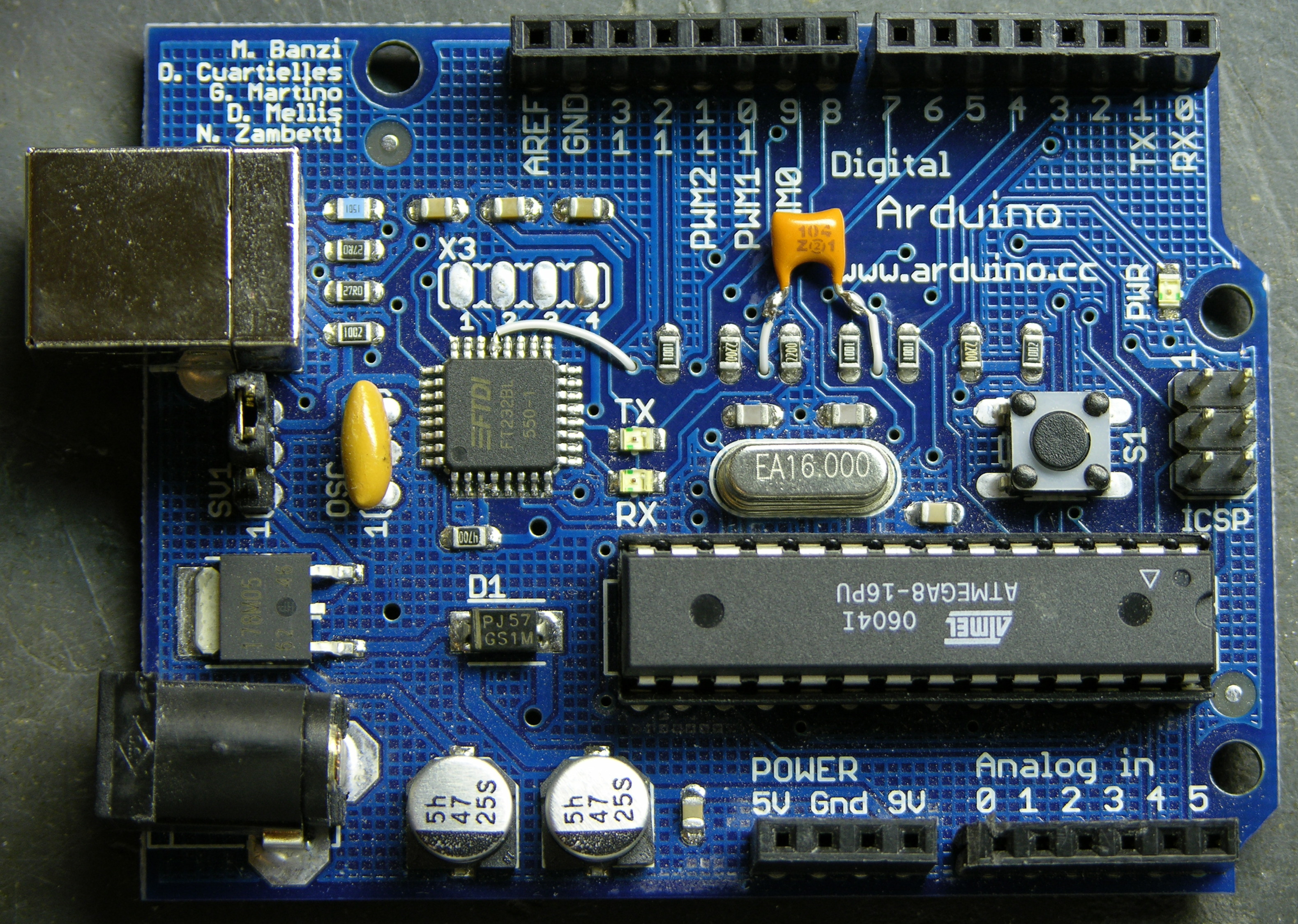
I got the datasheet for the FTDI FT232BL USB-serial chip, and for a moment got my hopes up higher than I should have. The DTR line is in the row toward the top of the Arduino board, and it looked as though it might already be broken out into the unpopulated, .1″-spacing X3 header. Nope, nope, it’s about the only line on that side that’s not already broken out. I was going to have to solder directly to the chip.
Given that it’s a 7mm-square LQFP with .8mm (.03″) lead spacing, I should perhaps have set it out with a thimbleful of Special Sheep Liniment to entice the Nac Mac Feegle to solder for me. But I have no dearth of hubris, and soldered it myself. Twice, in fact, the second time after cutting the other end of the wire too short to reach the capacitor.
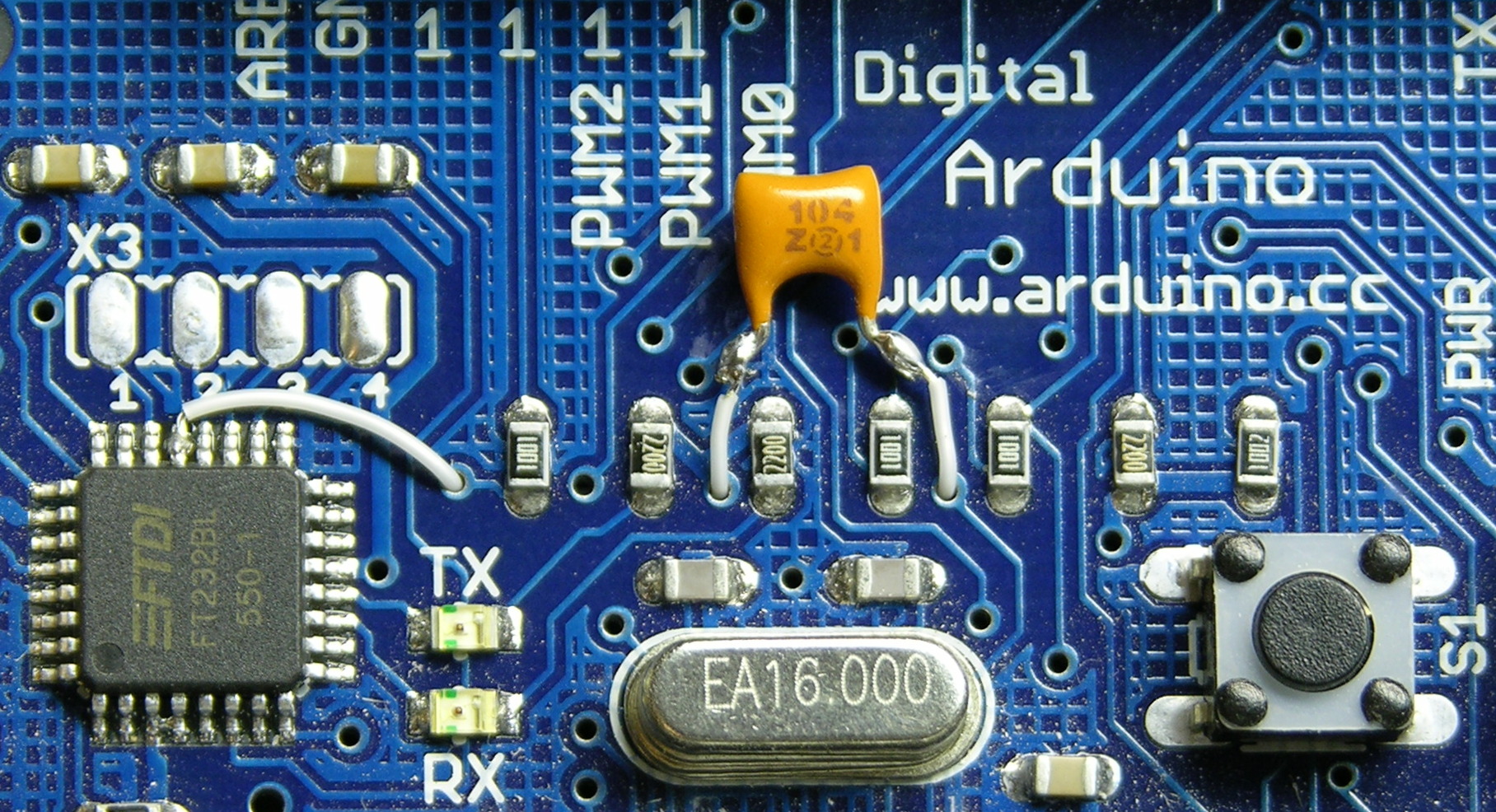
One side of the capacitor connects to the DTR line of the USB-serial chip, the fourth pin from the left on the upper edge. The other side connects to the reset line, which appears to be available only on the microprocessor, the ISP header, and the reset button. I chose the reset button on the underside of the board.
I could have used a capacitor with long leads, sleeved them, and connected them directly to the pins at both ends as in the serial board hack; but I thought it looked better to use wire-wrap wire.
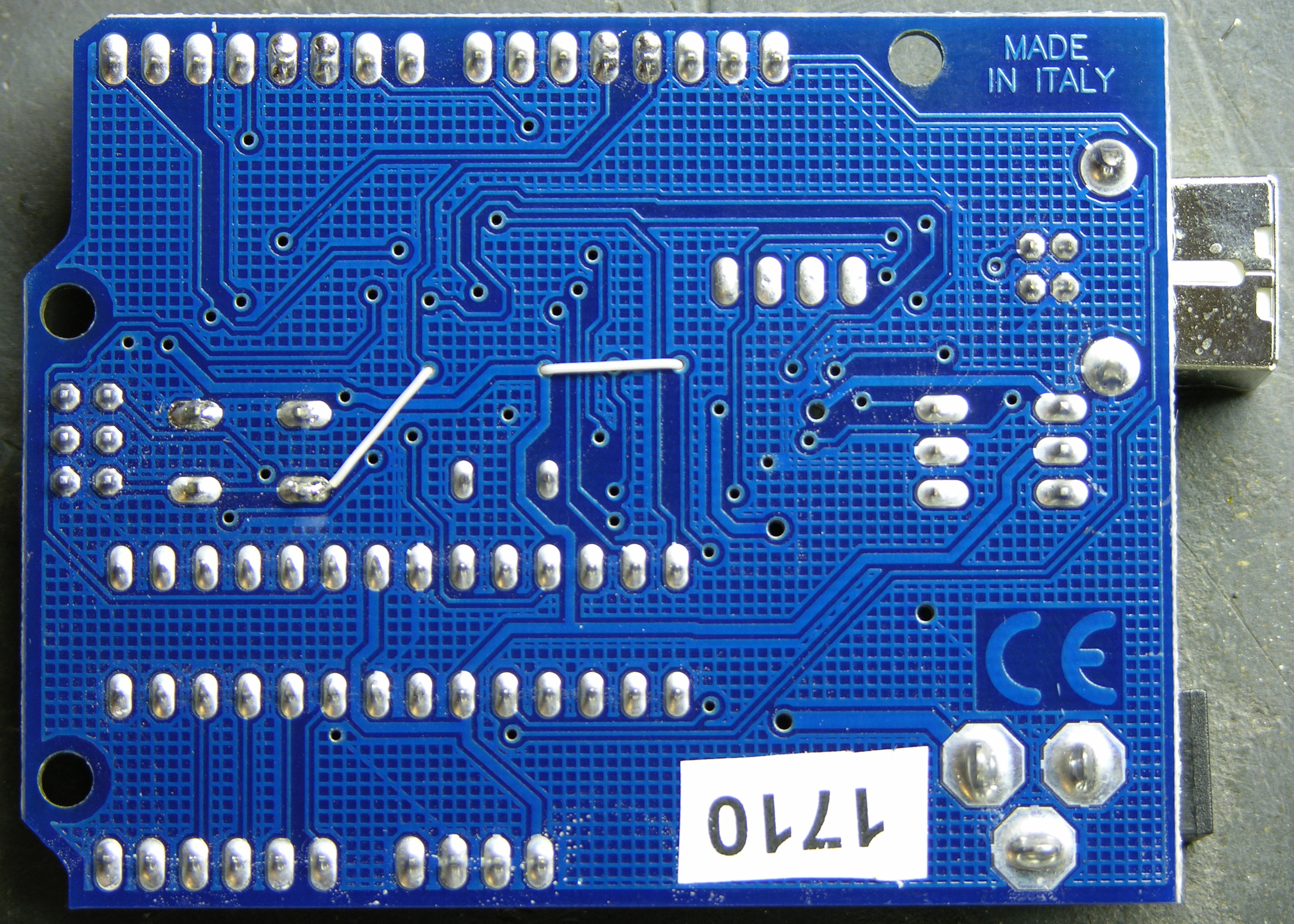
I laced the (insulated) wire-wrap wire through open vias in the board to keep things tidy and the capacitor snugged down. A few dots of glue would have done the same had I wanted to keep all the wires top-side, but this felt a little more artful to me. Plus it seemed easier to solder to the underside of the reset switch rather than the top, so I was feeding a wire to the back side of the board anyway.
I upgraded the integrated development environment to version 10, which adds the DTR-triggering, and tried it out. The host computer does indeed now reset the Arduino, and I can upload software to it without pressing the button! Hooray!
But there’s still about a 10-second delay after a boot, reset, or upload before the software starts running. Boooo!
One of the hacking guides suggested that the Arduino bootloader would need to be upgraded in order to reduce the reset delay, which makes sense. The IDE includes the ability to burn a new bootloader, for which the bootloader web page gives instructions. Burning the bootloader, unfortunately, can’t be done through the Arduino’s serial interface; it requires a separate AVR programmer.
Thus it was time to assemble my USBtinyISP kit from LadyAda.
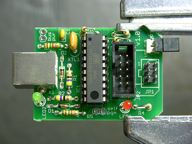
I bought it a while back in order to be prepared for programming ATmegas outside of the Arduino board. It’s an Atmel ATtiny chip interfacing directly between a USB connector and two cables for in-system programming. The board is nicely made, the instructions are clear enough for absolute beginners, and it was a joy to solder.
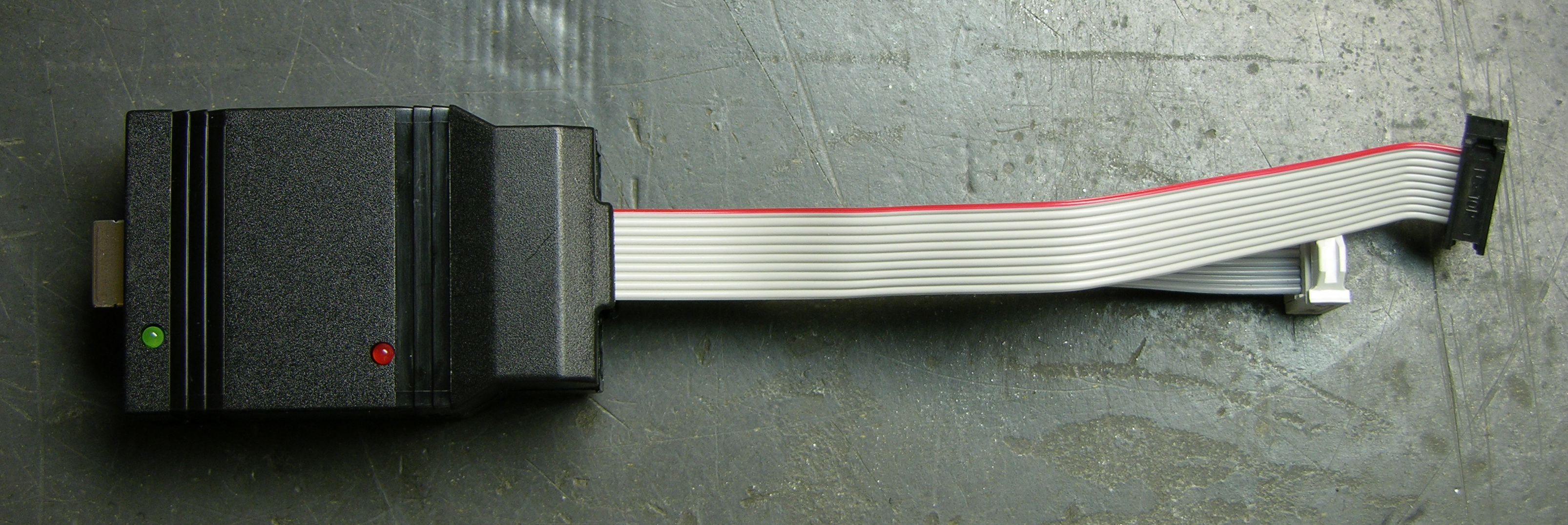
Fully assembled, it lives in a shell that makes me think of old serial line drivers; but the shell is somewhat customized to fit the USBtinyISP board (and vice-versa).
I read recently and have since forgotten the name of the little “columns” built into plastic enclosures (like toys) to hold PCBs in place; but no matter, since my point is that this case doesn’t have them. The USB end of the board had a lot of room to move and was a bit wibbly-wobbly, but I took the foam that the chip shipped in and packed it between the USB connector and the top of the case, which secured the whole thing nicely.
The term is mounting bosses, seen at Near Future Laboratory.
That done, I unplugged the Arduino’s USB connector, plugged the USBtinyISP into the Arduino’s ISP header and into my iBook’s USB, and burned a new bootloader. I went to the Arduino IDE’s Tools / Board menu and selected Arduino NG or older w/ ATmeta8, then Tools / Burn Bootloader / w/ USBtinyISP. The USBtinyISP’s programming light went on and IDE told me it was burning and would take a minute. Twiddle twiddle.
Finished. Disconnected the USBtinyISP and reconnected the Arduino. It didn’t seem to have my program on it any more, which I guess makes sense that doing low-level AVR programming would wipe the whole memory. I uploaded my code again; and when the upload finished, it took about 10 seconds to start the code. Hrm. Pressed reset, and it took about 10 seconds. HRM.
My Arduino is so old that it has the ATmega8 instead of the ATmega168. I don’t know whether that’s true of all Arduino USB boards, but it’s certainly true of mine.
It would appear that the ATmega8 bootloader image has not been updated for the auto-reset. Poo.
The bootloader source code is available online, but the ATmega8 code looks unusable. By that I mean that large sections of code are commented out, including the part that makes timeout after n seconds. (Yes, I’m saying it appears that it would wait forever for a software upload before starting your program.)
It looks to me like it’s been half-***ed patched with updates that have been made to the ATmega168 bootloader, but that parts that would have taken any effort to fix have been commented out rather than updated. Yes, I’m bitter.
See the comment from David Mellis, a developer of the Arduino, below. The timeout value is still present; I just didn’t look carefully enough. The ATmega8 bootloader code probably is what’s in the IDE, and it should be possible to recompile it with a shorter timeout. I’ll provide a further update once I get that worked out.
Interestingly, the ATmega168 bootloader code includes conditional compilation for many different ATmega chips, including the ATmega8. It seems likely that I could build it for the ATmega8 and get it to work. However, the bootloader web page says that the ATmega8 bootloader is only 1k rather than the newer bootloader’s 2k, an important savings given the ATmega8′s mere 8k of FLASH.
Fix the abandoned ATmega8 bootloader code myself? Sacrifice an extra 1k of program space by using the newer bootloader? Sigh.
Another option would be to buy Lady Ada’s preprogrammed ATmeta168 microcontroller. Of course I’d check first, but I think the ATmega8 and ATmega168 are pin-compatible. If that’s the case, I could pop in a 168 (preprogrammed from her, or straight from the factory and program it myself with the USBtinyISP) and be done with this. But it really grates on me to replace hardware when a software fix is perfectly viable.
And of course I could just try lying to my IDE about what chip I have and burning the ATmega168 bootloader into my ATmega8. But looking at the source code, there are enough differences between the ATmega168 and ATmega8 sections that I’m leery of doing this. I wouldn’t mind if it simply didn’t work, but I don’t know enough to be sure it wouldn’t damage the chip somehow. I’d rather live with the delay (for now) than destroy the only chip I have (for now).
The capacitor-reset hack was easily adapted to the Arduino USB, if you don’t mind a little fine-pitch soldering. Yay! That plus an upgrade to v10 of the Arduino IDE allow the host computer to reset the Arduino when uploading new software, relieving you of pressing the reset button each time. Yay! But I don’t yet have a solution to reduce the reset delay on a board using the ATmega8 microcontroller. Boo!