With the Spider mainboard online and talking to OctoPrint, a cabling issue corrected, and a pinning issue I-thought-dealt-with-but-actually-no, documenting-soon, it was time to work through Voron’s initial startup checks to verify all pinning and basic functionality. The document’s order of operations is fantastic; but too often it says what to do and doesn’t say how to do it. Let’s fill in some gaps.
Voron 2.4 Build — Initial Startup Checks
August 29th, 2022 by Keith NeufeldVoron 2.4 Build — Figuring Out Spider Mainboard Fan Connections
August 27th, 2022 by Keith NeufeldWith OctoPrint talking to the Klippy host software on the Pi talking to the Klipper firmware on the Spider mainboard and the Voron’s LCD lit up and control panel working, I could see that the firmware was able to read hotend and platform temperatures and I used the printer’s control panel to test each of the two heaters. The heaters worked; but I noticed that when heating the hotend, the part-cooling fan came on and the heat break fan didn’t. Probably the fan connections were swapped?
I’d wired the printer per Fysetc’s diagram for this printer on a later revision of their Spider board because it was the only diagram I could find at the time and I wanted to be able to use a sample configuration file as a starting point rather than do the whole pin configuration from scratch. Tempting though it was to just swap the two fan plugs on the mainboard and be done with it, I went back to the wiring diagram from the Fysetc Spider board GitHub page first for a closer look.
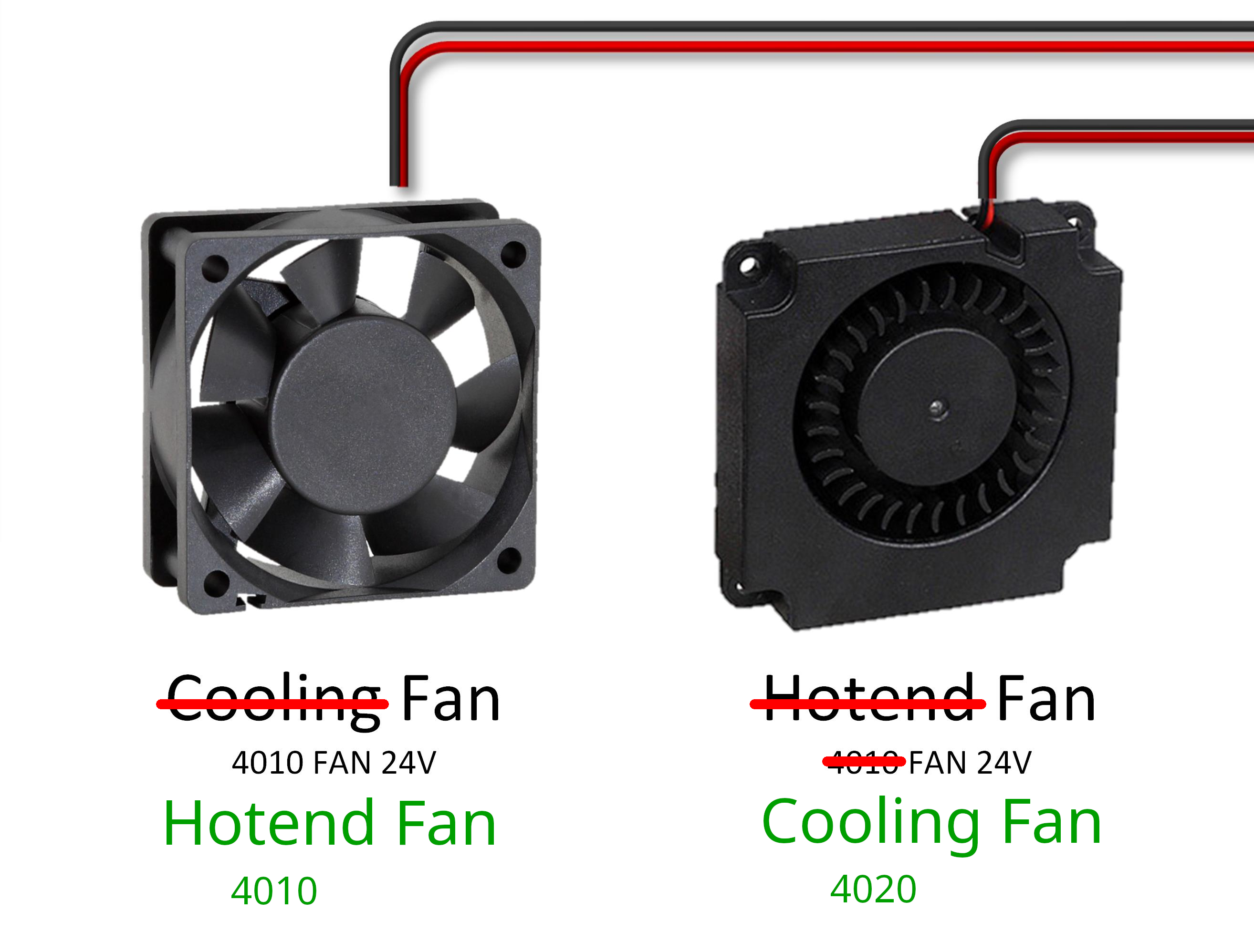
Oh. Oh, I see. I had previously noticed that Fysetc had labeled both of them as 4010 fans; but I hadn’t noticed that they had swapped the labels of which fan served which function. I had originally connected my fans by tracing which function was connected to which Spider port; but with the functions swapped on the diagram, my wiring was swapped on my board. I now changed my wiring to match the Fysetc diagram’s intent (and the sample printer.cfg‘s configuration) and noted the error in the wiring diagram here for later reference. The fans now behaved as they should.
Voron 2.4 Build — Spider Mainboard Klipper Firmware Installation and Startup
August 27th, 2022 by Keith NeufeldAfter running the Spider mainboard test firmware as a sanity check of the Spider’s operation and LCD cabling, several paths are available to get Klipper installed onto the Spider. My factors were:
- not feeling like continuing to power the Pi from an external source, even during the firmware process
- not feeling like continuing to re-jumper the Spider board for DFU programming
- my Spider should now have a working 32K bootloader installed
That led me directly to SD-card firmware installation, which was easy-peasey since I have another *nix-ey computer available for one step.
Voron 2.4 Build — Fysetc Spider MB Test Firmware
August 21st, 2022 by Keith NeufeldI still have notes to share about the rest of the mechanical assembly and I have so many thoughts about the wiring; but I just powered up the Voron to test the mainboard and want to record my thoughts while they’re fresh.
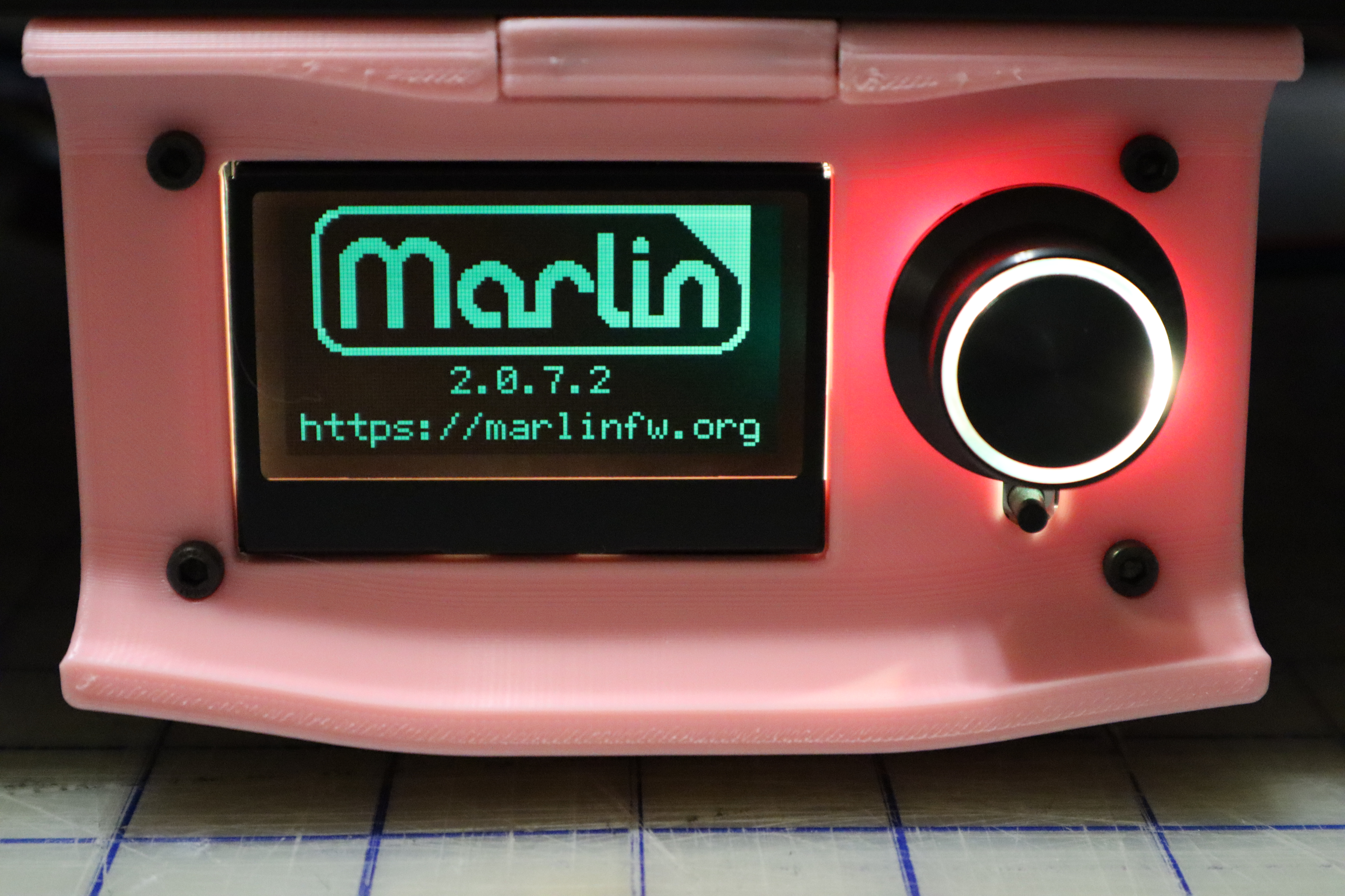
No, my Voron won’t run Marlin; but the test firmware does.
Random Weekend CAD and Printing
June 19th, 2022 by Keith NeufeldMusing on Nozzle Height Above Build Surface
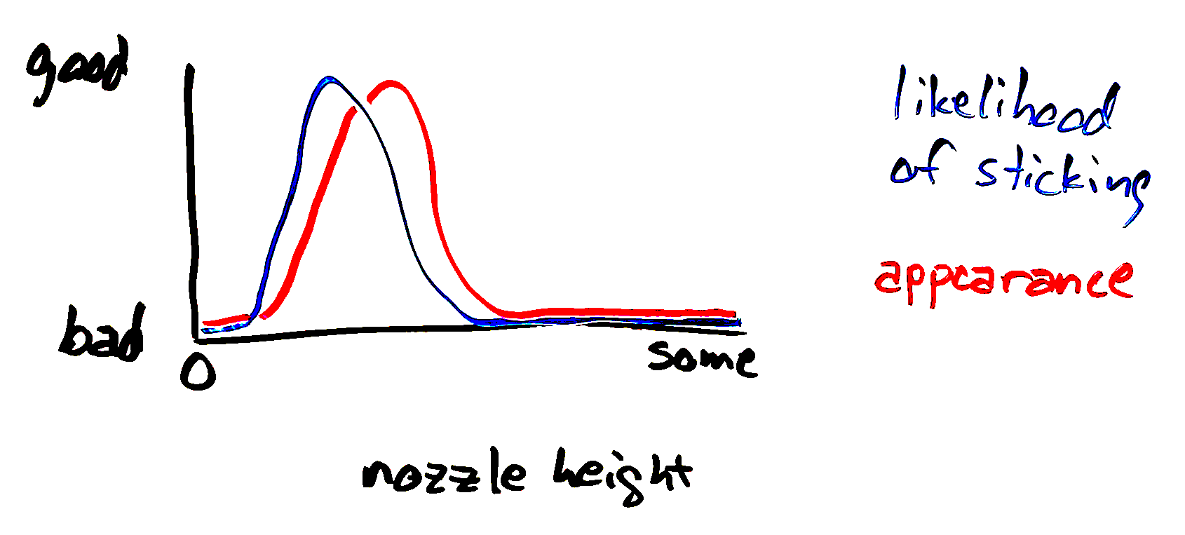
June 13th, 2022 by Keith NeufeldI’d always assumed that lowering a 3D printer’s nozzle closer to the build surface causes the extrusion to stick better and better until it’s pressing hard enough, at which point the stickiness asymptotically approaches maximum; and of course once there’s no space left between the nozzle and build surface, one can no longer be said to be sticking filament to the surface.
Thus if a particular filament sticks well to a particular surface, optimize for the best appearance — first layer nicely joined with no roughness from overextrusion nor from the nozzle troughing the filament it’s laying down. If a filament doesn’t stick well to a surface, lower the nozzle until it does; and no need to fine-tune for adhesion — overshooting will only hurt the appearance, not adhesion.
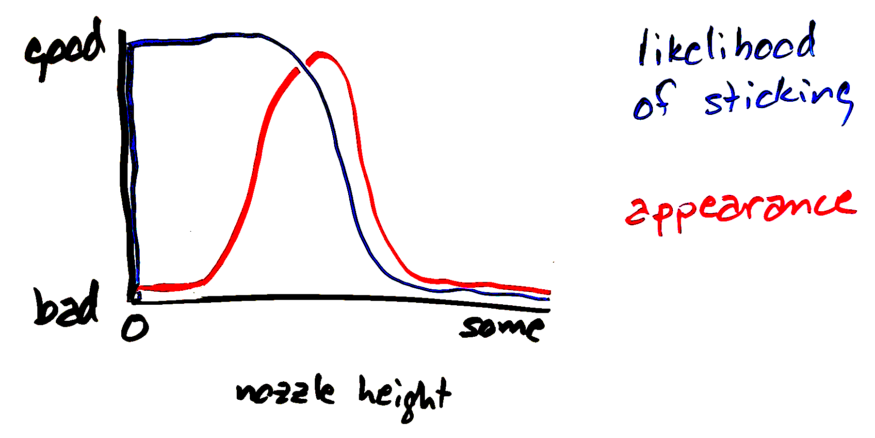
My friend Cort has started to convince me of a different model — that pressing the filament too hard makes it stick less well, whether through an action similar to tiddlywinking your way along the length of a rubber gasket lying on a workbench or by some other phenomenon.
In this model, driving the nozzle too close to the build surface is self-defeating and to get a troublesome filament to stick, one should lower the nozzle very carefully in fine steps to avoid overshooting the peak of the adhesion curve. Cort’s patient tuning this past weekend of one of my Enders on which I could no longer get anything to stick bears that out.
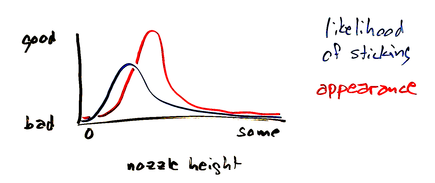
Of course, with some filaments and slicer profiles, the graph looks more like this — peak adhesion isn’t actually good, at best kinda good.
More on this topic soon.
Voron 2.4 Build — Actual AB Motor Orientation
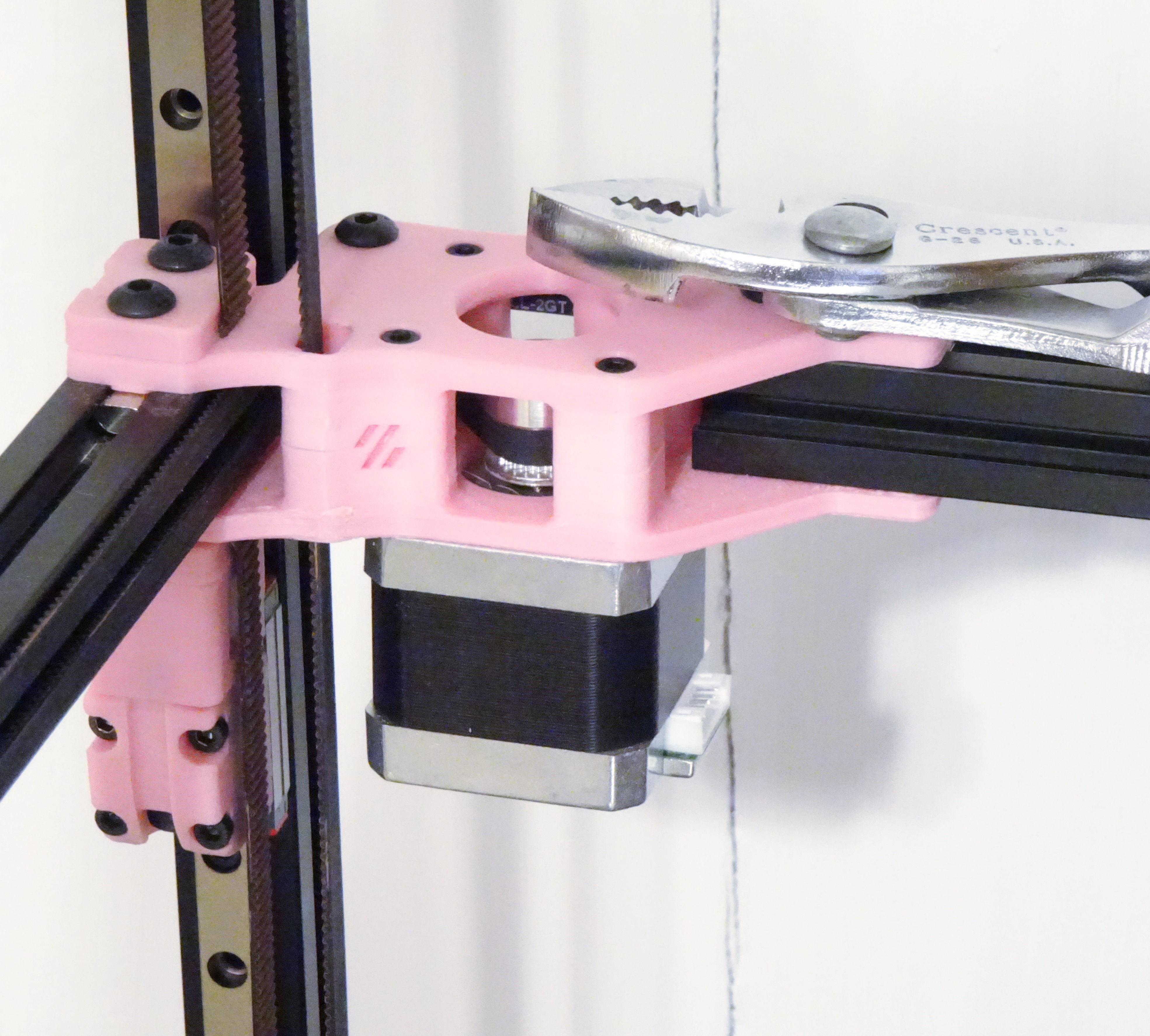
June 1st, 2022 by Keith NeufeldSo actually the AB stepper motors need to be installed with their connectors facing each other, toward the center of the back plane of the printer. The 2.4r1 instructions don’t mention this at all; the 2.4r2 instructions mention it clearly.
If you installed them with the connectors facing out the back, especially if you did that based on my earlier and now corrected misinformation, be apprised that you can correct them merely by loosening the AB belt tensioners on the front of the printer, removing the three long M3 screws that go all the way through each of the blocks into the steppers, rotating the steppers in place, and reassembling.
If you know someone who’s a dope and already took the top off of the A or B block, spilling precious towers of bearings and washers, let them know that it’s even easy to recover from that. Remove both AB steppers from their blocks to get lots of slack in both belts; hold long M4 machine screws up from below through the bearing positions and rebuild the towers; nudge the belts out of the way of plastic parts; put the lid back on; and push the M5 machine screws down through the bearing stacks, pushing the temporary M4s out of the way as you go. I mean as they go.
Voron 2.4 Build — Mains Power Panel
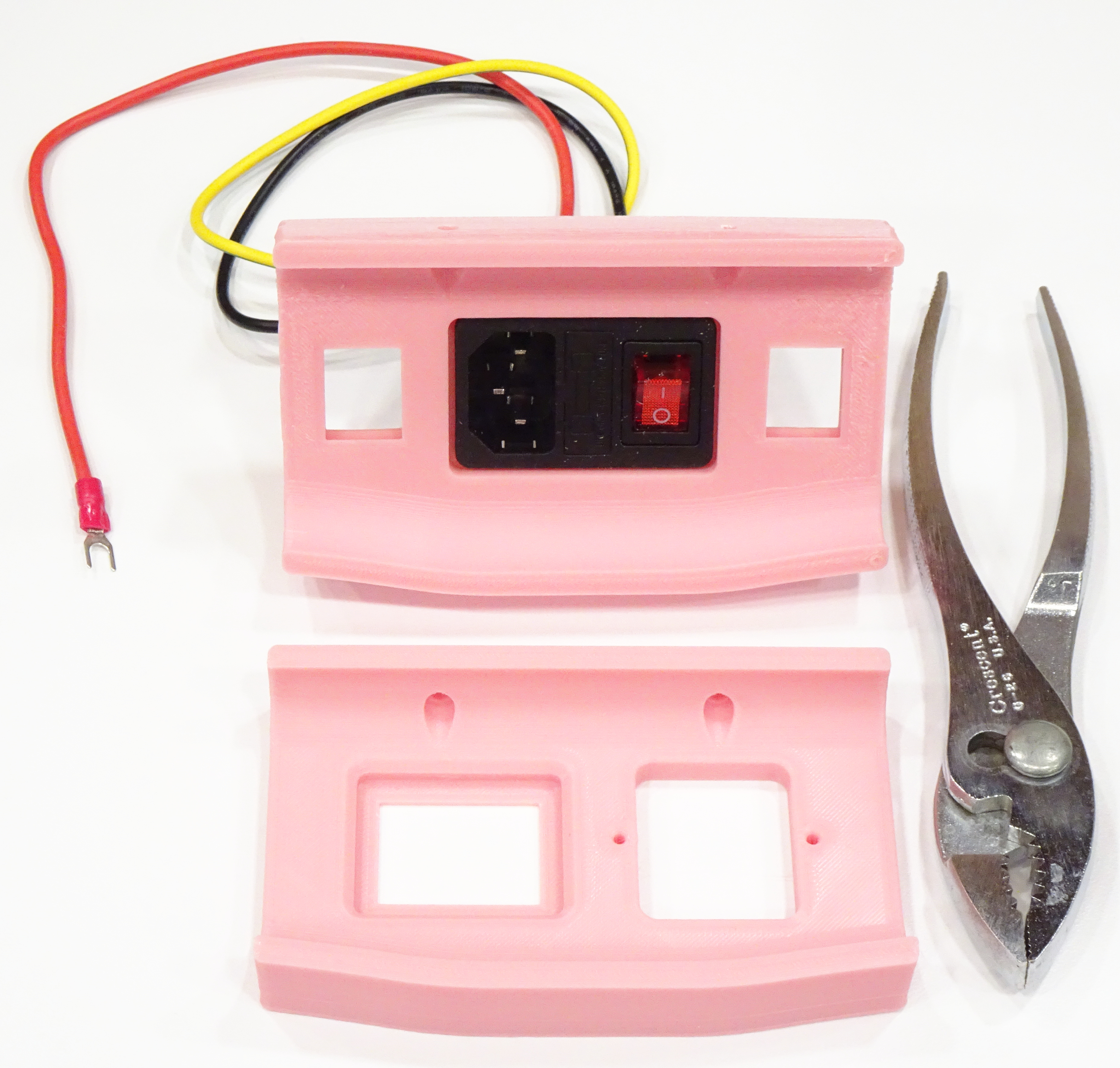
May 30th, 2022 by Keith NeufeldThe 2.4r1 assembly manual only shows assembly for the plug_panel_filtered_mains.stl (lower), which is what I printed while waiting for my kit to ship with the power inlet that fits the plug_panel.stl (upper). Don’t be fooled like me.
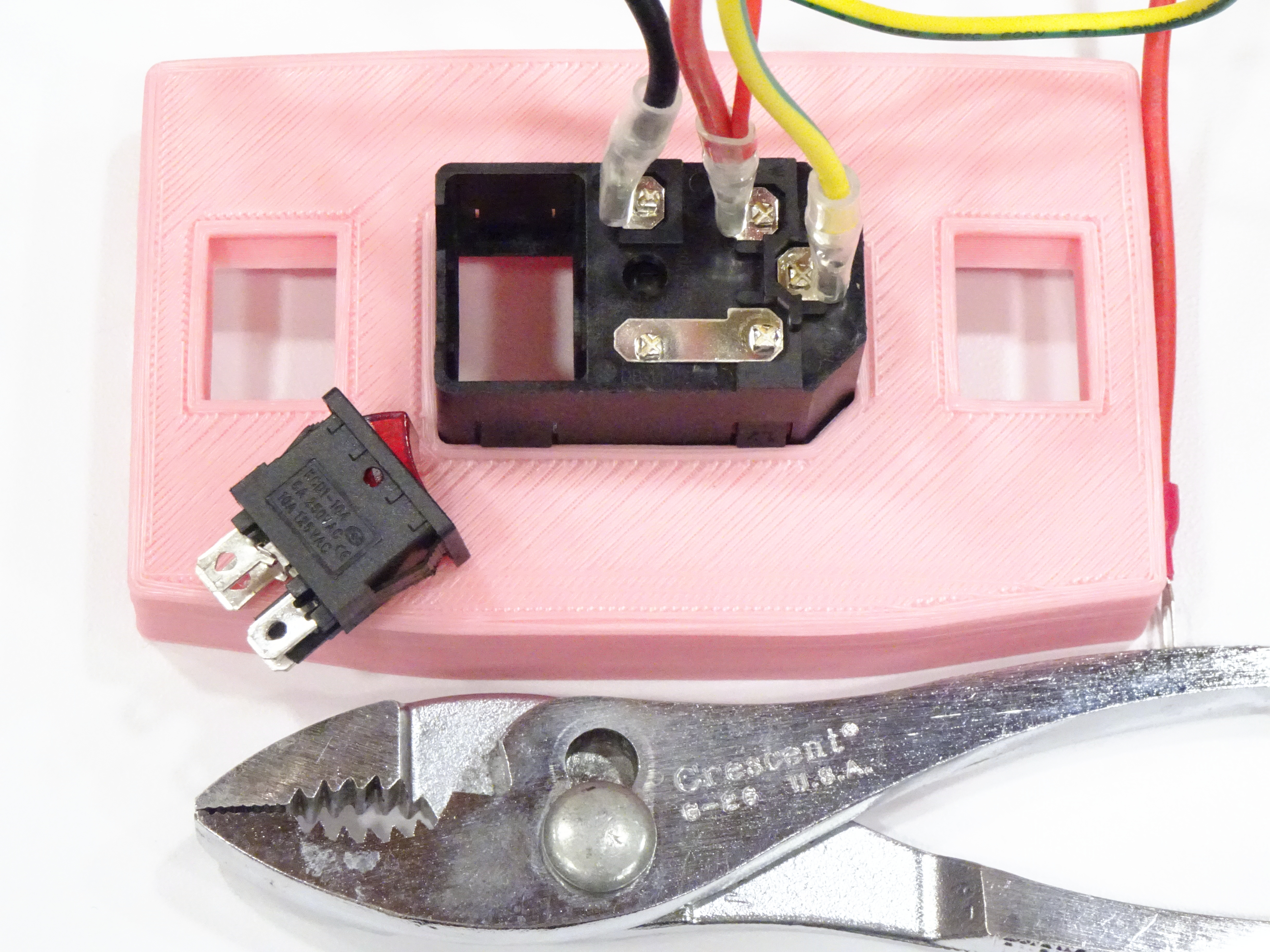
On the subject of the power inlet … the default configuration puts the power switch oriented with off up and on down, which I cannot abide. A small prying tool on the switch’s latches frees it from the inlet housing to be reinstalled in the One True Orientation. Just take a snapshot of the power wiring on your switch before undertaking such shenanigans.
Voron 2.4 Build — Printhead Assembly
May 30th, 2022 by Keith NeufeldA few notes on assembling the printhead:
The 2.4r2 assembly manual has much more detail than the 2.4r1, very much appreciated.
Even the 2.4r2 manual leaves it to you to figure out how to assemble whatever hot end you have. Because my kit came with an E3D-v6 clone hot end, I found these self-proclaimed outdated E3D-v6 assembly instructions that direct you to better-maintained instructions that no longer exist, and followed the link within these instructions to another set for installing the old-style thermistor.
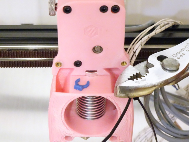
The 2.4r2 instructions and their diagrams don’t speak to this detail, but later assembly makes it clear that one does leave the (here black and barely visible) plastic ring that guides the PTFE tube into the cold end but one omits the (here blue) clip that in some uses locks the ring onto the PTFE tube.
After measuring and marking the PTFE tube length, I should have cut it with my PTFE tubing cutter but I was impatient and cut it with diagonal cutters, then mashed it round again. I look forward to regretting that later.
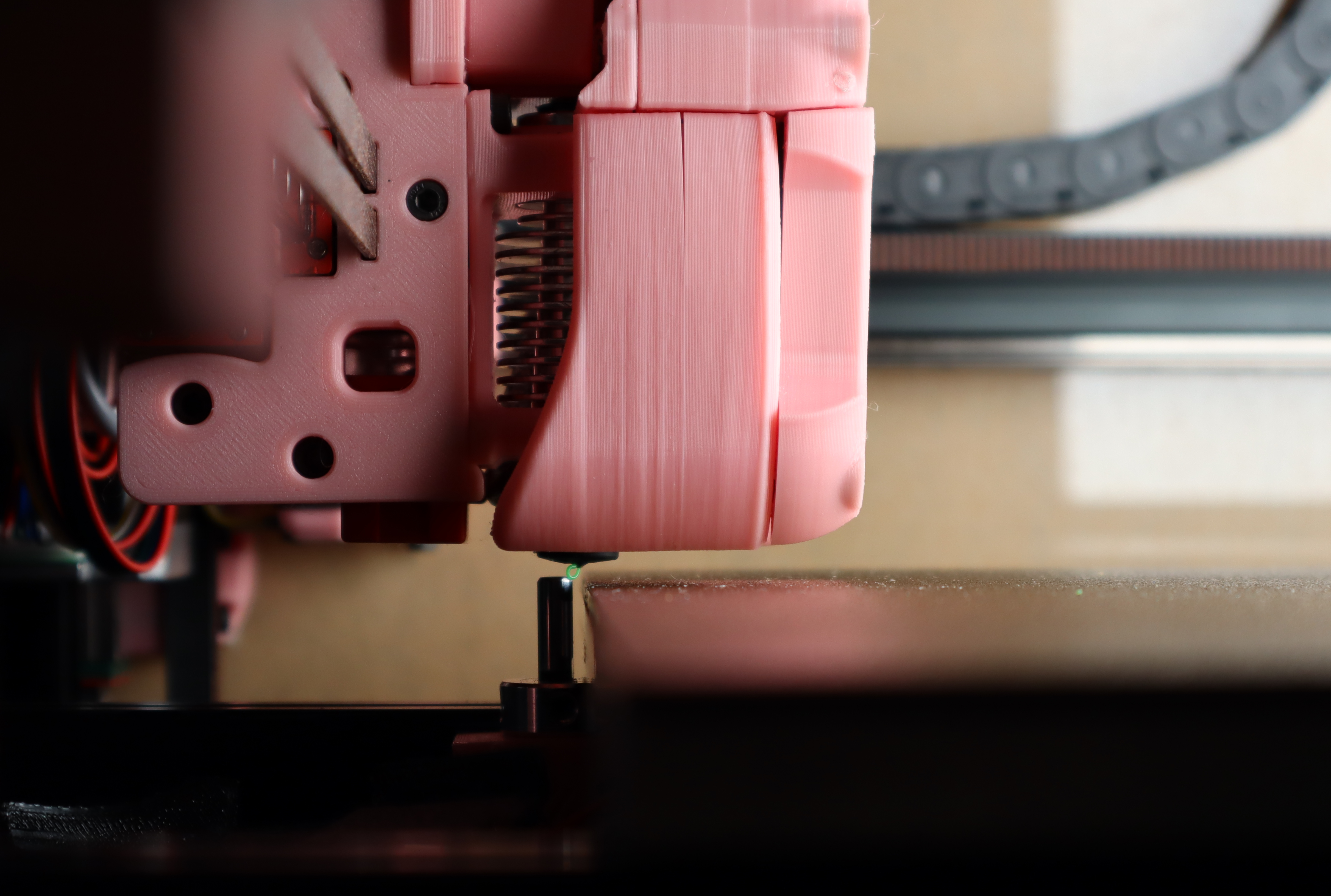
I’ve completed the printhead assembly and have yet to figure out what is meant by this instruction when mounting the hot end to the X carriage:
INDEXING BOLTS
The bolts are used to index the tool cartridge. Leave them slightly loose so that the cartridge can be slid out.
The 2.4r1 instructions make no mention of where the pinion gear should be positioned on the motor shaft. The 2.4r2 instructions give a dimension and also appear to show a printable shim that will position it correctly, which is a fantastic idea (though I didn’t download the STLs and print it myself).
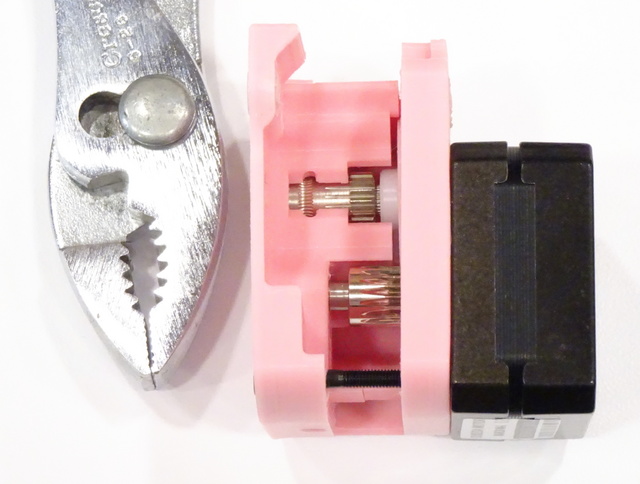
The white nylon drive gear in my Fysetc kit wasn’t installed fully into position at the factory; you can see a bit of splined shaft between the hub of the nylon gear and the Bondtech-style filament gear; and you can see that the filament groove is misaligned between the Bondtech-style gear and the housing. I took it back out, supported the back end of the nylon gear with a large nut, and pressed it the rest of the way into position in a bench vise.
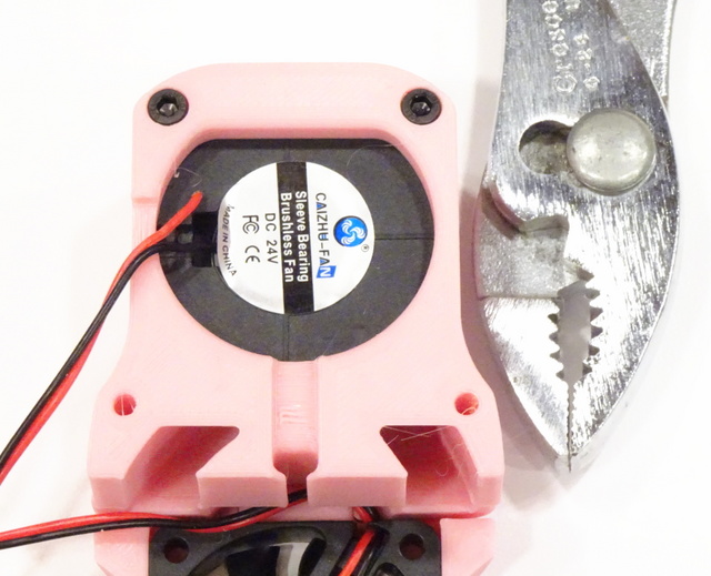
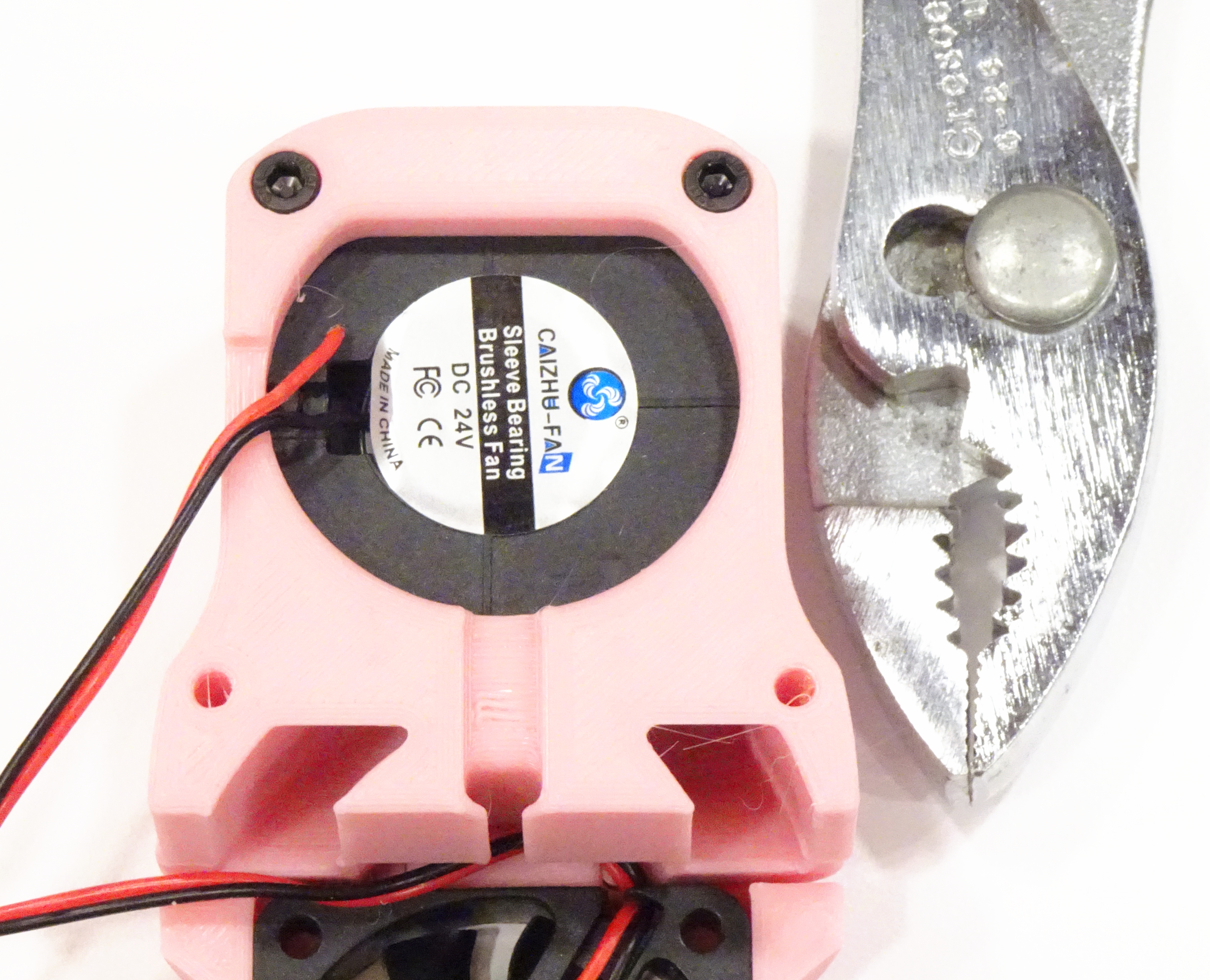
There’s just barely room between the 4020 blower fan and the printed housing to leave the fan wires routed through their factory strain relief, differently than shown here. You should do that. So you don’t break off the fan wires. Like I did. And have to solder one back on.
After reattaching and routing the wires back through the strain relief, I covered the solder joints with hot glue to provide extra strain relief. I did note first that the black surface immediately beneath the wires is the fan and that it’s probably counterproductive to fill the whole cavity with glue.
Since I’d removed the sticker to have a teence more room to solder, I added a couple of drops of lightweight oil to the fan shaft before closing things back up.
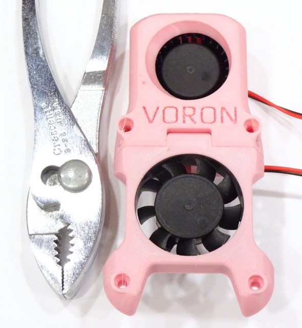
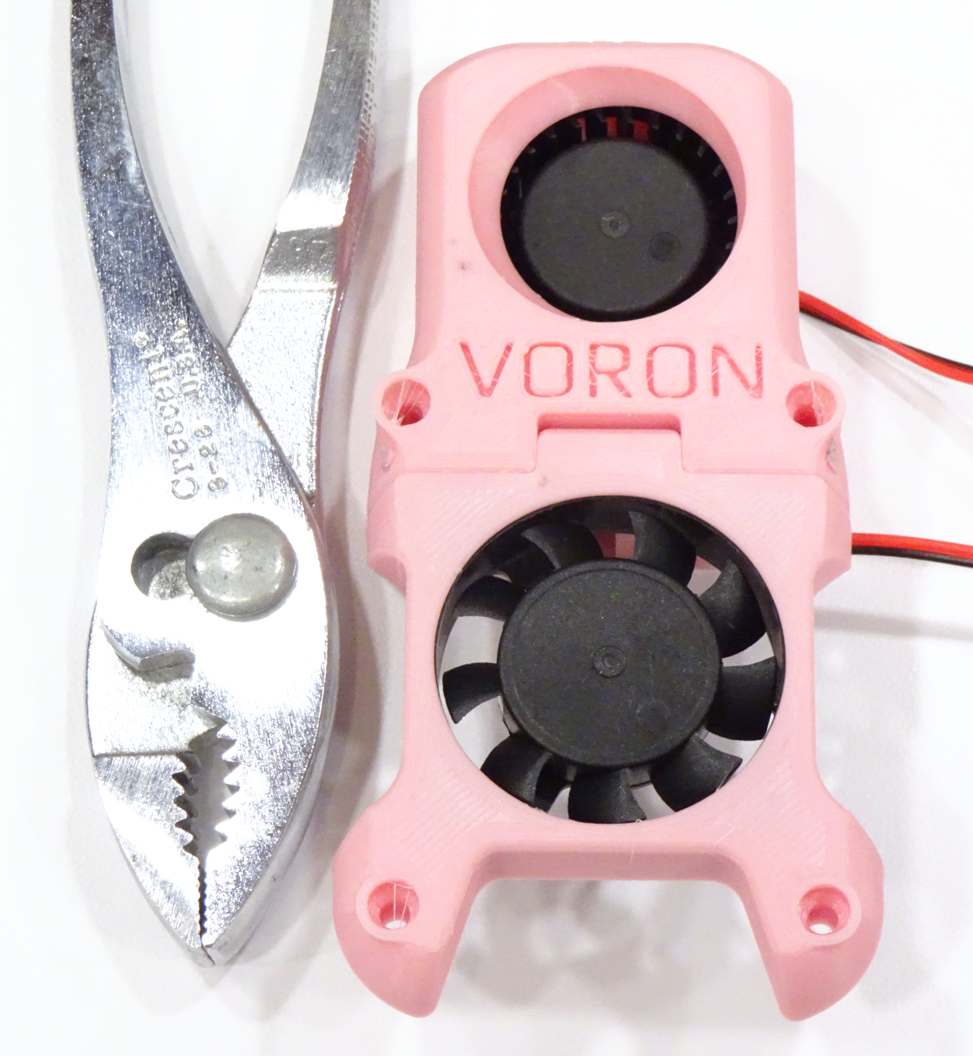
The instructions and diagrams are hard to read regarding the orientation of the (lower) 4010 fan; but sticker-side-in blows air onto the cold end rather than sucking air past it, and more importantly, looks better.
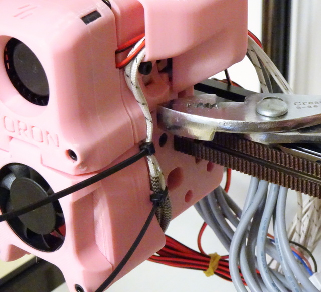
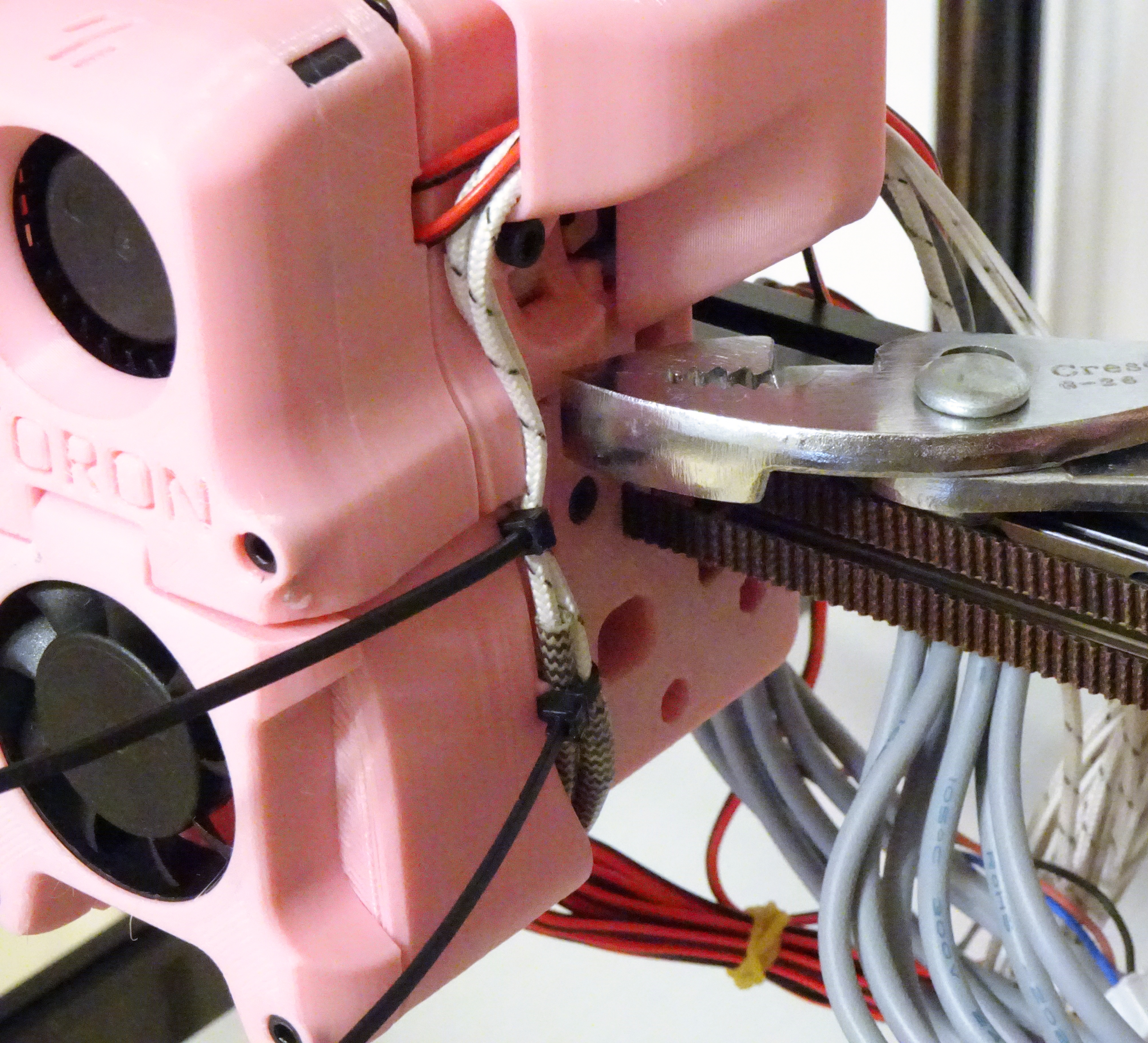
I presume the little notches in the toolhead housing are for cable ties (which I have since trimmed).
Voron 2.4 Build — AB Belts
May 27th, 2022 by Keith NeufeldI took a break from Voron assembly last November due to being quite vexed at crucial information omitted from the assembly manual and the extra effort in interpretation and rework it caused me.
With a little one on the way [that is, I just ordered a Voron 0.1 parts kit], I figured it was time to get the 2.4 assembly finished; and thankfully, since November the assembly manual has been overhauled from r1 to r2 and is much, much, much better. If you’re assembling a Voron 2.4 and you don’t already have the r2 assembly manual, go download it right now. You can thank me later.
Before my hibernation, I had assembled and installed the gantry. All of my frustrations about the instructions that drove me away at the time have now been addressed, save one, presented here for your sanity:
The instructions say to route the AB belts by clamping one end onto the carriage, then threading them through the entire gantry, then clamping the second end onto the carriage. I tried that at least twice and found it difficult each time to fish the belt ends through the AB blocks in the back corners. It was much easier for me to start in the middle by pushing both ends of each belt through this opening and around their drive pulleys, then threading the belts outward toward both ends.
As I resume assembly, I’ll compare 2.4r1 and 2.4r2 instructions, only calling out issues with the r2 instructions.